1
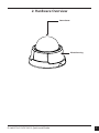
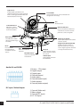
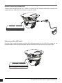
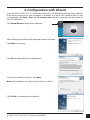
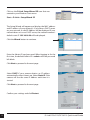
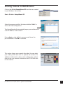
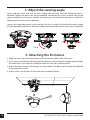
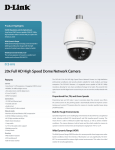
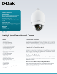
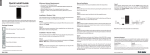
Quick Install Guide
Fixed Dome Network Camera
This document will guide you through the basic installation
process for your new D-Link Network Camera.
DCS-6112/DCS-6113
Documentation also available on
CD and via the D-Link Website
DCS-6112/DCS-6113 Quick Install Guide
This installation guide provides basic instructions for installing the DCS-6112/DCS-6113
Network Camera on your network. For additional information about how to use the camera,
please see the User Manual which is available on the CD include in this package or from the
D-Link support website.
Installation Steps
1.
2.
3.
4.
5.
6.
Verify the package contents against the list below.
Hardware Overview
Hardware Installation
Configuration with Wizard
Adjust the Viewing Angle
Attaching the Enclosure
1. Package Contents
• DCS-6112/DCS-6113 Network Camera
• Manual and Software on CD-ROM
• CAT5 Ethernet Cable
• AV / Power cable
• Power Adapter
• Screwdriver
• Screw
• Alignment Sticker
• Quick Install Guide
• Cable Tie
If any of the above items are missing, please contact your reseller.
2
D-Link DCS-6112/DCS-6113 Quick Install Guide
2. Hardware Overview
Dome Cover
Plastic housing
D-Link DCS-6112/DCS-6113 Quick Install Guide
3
Light Sensor
Judges lighting conditions and
switches between day mode and night
mode accordingly (Control IR-LED and
ICR on/off ) (DCS-6113 only).
Infrared LEDs
Used to illuminate the camera's field of view
at night (DCS-6113 only).
Lens
Fixed focus lens.
3-Axis Mechanism
Adjust the camera’s
image to achieve the
desired orientation.
Ethernet (PoE) Port
RJ-45 connector for an Ethernet
cable which can also be used to
power the camera using PoE.
MicroSD Card Slot
Local MicroSD card for
storing recorded images
and video.
Reset
Press and hold
this button for 10
seconds to reset the
camera.
LED
Power and network
indicator.
Audio I/O and DI/DO
DC input / Video Output
4
NTSC/PAL Switch
Switch for NTSC/PAL
video format.
DC Input
Connects to the 12V DC
power adapter to power
the camera.
Video Output
Video output connector
for TV/Monitor.
Audio Input / Output
Audio input/output connector for
external speaker.
Digital Input (DI) /Output (DO)
DI/DO connectors provide a
physical interface to send and
receive digital signals to and from
a variety of external devices.
1: Power + 12V output
2: Digital output
3: Digital input
4: Ground (power)
5: Audio input
6: Ground (audio input)
7: Audio output
8: Ground (audio output)
1: Ground (Video out)
2: Video output
3: Ground (DC input)
4: DC 12V input
D-Link DCS-6112/DCS-6113 Quick Install Guide
3. Hardware Installation
Mounting to a Ceiling or a Wall
1. Locate an area on the ceiling or wall which is suitable of supporting the weight of the camera.
2. Attach the alignment stencil to the ceiling or wall.
3. Drill two pilot holes where the holes of the alignment stencil are located.
4. Insert the supplied plastic anchors into the drilled holes, and align the holes at the base of
the camera with the plastic anchors.
5. The camera can be mounted with the cable routed through the ceiling, wall or from the side.
6. Insert the provided screws through the holes. Use a screwdriver to tighten and secure.
D-Link DCS-6112/DCS-6113 Quick Install Guide
5
General Connection (without PoE)
Connect the network camera to a switch or router via an Ethernet cable then connect the
supplied power cable from the camera to a power outlet.
Connection with a PoE Switch
If using a PoE switch or router, connect the network camera to the switch or router via an
Ethernet cable, which will provide both power and data transmission over a single cable.
6
D-Link DCS-6112/DCS-6113 Quick Install Guide
4. Configuration with Wizard
Insert the DCS-6112/DCS-6113 CD into your computer's CD-ROM drive to begin the installation.
If the autorun function on your computer is disabled, or if the D-Link Launcher fails to start
automatically, click Start > Run. Type D:\autorun.exe, where D: represents the drive letter of
your CD-ROM drive.
Click Setup Wizard to begin the installation.
After clicking Setup Wizard, the following window will open.
Click Next to continue.
Click Yes to accept the License Agreement.
To start the installation process, click Next.
Note: The installation may take several minutes to finish.
Click Finish to complete the installation.
D-Link DCS-6112/DCS-6113 Quick Install Guide
7
Click on the D-Link Setup Wizard SE icon that was
created in your Windows Start menu.
Start > D-Link > Setup Wizard SE
The Setup Wizard will appear and display the MAC address
and IP address of your camera(s). If you have a DHCP server
on your network, a valid IP Address will be displayed. If your
network does not use a DHCP server, the network camera's
default static IP 192.168.0.20 will be displayed.
Click the Wizard button to continue.
Enter the Admin ID and password. When logging in for the
first time, the default Admin ID is admin with the password
left blank.
Click Next to proceed to the next page.
Select DHCP if your camera obtains an IP address
automatically when it boots up. Select Static IP if the
camera will use the same IP address each time it is
started.
Click Next to proceed to the next page.
Confirm your settings and click Restart.
8
D-Link DCS-6112/DCS-6113 Quick Install Guide
Viewing Camera via Web Browser
Click on the D-Link Setup Wizard SE icon that was created
in your Windows Start menu.
Start > D-Link > Setup Wizard SE
Select the camera and click the button labeled "Link" to
access the web configuration.
The Setup Wizard will automatically open your web browser
to the IP address of the camera.
Enter admin as the default username and leave the
password blank. Click OK to continue.
This section shows your camera’s live video. You can select
your video profile and view or operate the camera. For
additional information about web configuration, please
refer to the user manual included on the CD-ROM or the
D-Link website.
D-Link DCS-6112/DCS-6113 Quick Install Guide
9
5. Adjust the viewing angle
Loosen the pan screw and turn the lens module left and right until the desired position is
achieved. Tighten the pan screw once completed. Loosen the tilt screws on both sides of the
camera and then turn the lens module up and down until the desired position is achieved.
Tighten the tilt screws once completed.
Loosen the image adjustment screw and turn the lens to adjust the network camera’s image
until the desired orientation is achieved. Tighten the image adjustment screw once completed.
Loosen
Rotate
350°
Tighten
Pan 350°
Tilt 85°
6. Attaching the Enclosure
1. Align the inner-side of the black cover with the notch on both sides of the lens.
2. If you choose to feed the cable through the ceiling or wall, arrange the cable neatly through
the cable hole. If you choose to feed the cable from the side, remove plate A.
3. Attach the dome cover to the camera as shown below. The dome cover cannot be attached
if the angle does not fit.
4. Finally, make sure all parts of the camera are installed securely.
A
10
D-Link DCS-6112/DCS-6113 Quick Install Guide
Notes
D-Link DCS-6112/DCS-6113 Quick Install Guide
11
Technical Support
D-Link’s website contains the latest user documentation and software updates
for D-Link products.
U.S. and Canadian customers can contact D-Link Technical Support through
our website or by phone.
United States
Telephone
(877) 354-6555
World Wide Web
http://support.dlink.com
Canada
Telephone
(877) 354-6560
World Wide Web
http://support.dlink.ca
Version 1.0
October 7, 2011
Copyright ©2011 D-Link Corporation/D-Link Systems, Inc. All rights reserved. D-Link and the D-Link logo are registered trademarks
of D-Link Corporation or its subsidiaries in the United States and other countries. Other trademarks are the property of their
respective owners. Product specifications, size and shape are subject to change without notice, and actual product appearance
may differ from that depicted on the packaging. Visit www.dlink.com (US) or www.dlink.ca (Canada) for more details.