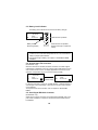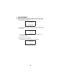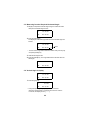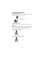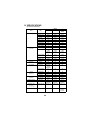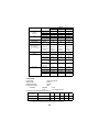
1
INSTRUCTION MANUAL
DIGITAL THEODOLITE
DT-200/200L SERIES
FOREWORD
Thank you for purchasing the TOPCON Digital Theodolite. For the best performance of the instruments, please carefully read these instructions and
keep them in a convenient location for future reference.
1
General Handling Precautions
Before starting work or operation, be sure to check that the instrument is
functioning correctly with normal performance.
Do not submerge the instrument into water.
The instrument can not be submerged underwater.
The instrument is designed based on the International Standard IP66,
therefore it is protected from the normal rainfall.
Setting the instrument on a tripod
When mounting the instrument on a tripod, use a wooden tripod when possible. The vibrations that may occur when using a metallic tripod can effect the
measuring precision.
Installing the tribrach
If the tribrach is installed incorrectly, the measuring precision could be
effected. Occasionally check the adjusting screws on the tribrach. Make sure
the base fixing lever is locked and the base fixing screws are tightened.
Guarding the instrument against shocks
When transporting the instrument, provide some protection to minimize risk
of shocks. Heavy shocks may cause the measurement to be faulty.
Carrying the instrument
Always carry the instrument by its handgrip.
Exposing the instrument to extreme heat.
Do not leave the instrument in extreme heat for longer than necessary.
It could adversely affect its performance.
Sudden changes of temperature
Any sudden change of temperature to the instrument or prism may result in a
reduction of measuring distance range, i.e when taking the instrument out
from a heated vehicle. Let instrument acclimate itself to ambient temperature. When a high degree of precision is required for measurement, provide
shade against direct sunlight for the instrument and tripod.
Battery level check
Confirm battery level remaining before operating.
Store with the batteries removed, when operation is halted for more than a
month. Leaving the batteries attached for extended period of time can result
in battery leakage, which may lead to malfunctioning.
2
Notice on Transceiver
When using high output transceiver etc., make sure it does not come near
the instrument.
Opening the carrying case
When opening the carrying case and taking out the instrument, place the
case horizontally, then open the case.
3
Display for Safe Use
In order to encourage the safe use of products and prevent any danger to the
operator and others or damage to properties, important warnings are put on
the products and inserted in the instruction manuals.
We suggest that everyone understand the meaning of the following displays
and icons before reading the “Safety Cautions” and text
Display
Meaning
WARNING
Ignoring or disregard of this display may lead to the
danger of death or serious injury.
CAUTION
Ignoring or disregard of this display may lead to personal injury or physical damage.
● Injury refers to hurt, burn, electric shock, etc.
● Physical damage refers to extensive damage to buildings or equipment and
furniture.
Safety Cautions
WARNING
•There is a risk of fire, electric shock or physical harm if you attempt
to disassemble or repair the instrument yourself.
This is only to be carried out by TOPCON or an authorized dealer,
only!
•Laser beams can be dangerous, and can cause eye injury's if used
incorrectly.
Never attempt to repair the instrument yourself.
•Cause eye injury or blindness.
Do not stare into beam.
•Cause eye injury or blindness.
Do not look at the sun through a telescope.
•High temperature may cause fire.
Do not connect the battery to an instrument while it is charging.
•Risk of fire or electric shock.
Do not use a wet battery or charger.
•May ignite explosively.
Never use an instrument near flammable gas, liquid matter, and do
not use in a coal mine.
4
•Battery can cause explosion or injury.
Do not dispose in fire or heat.
•Risk of fire or electric shock.
Do not use any power voltage except the one given on manufacturers instructions.
•Battery can cause outbreak of fire.
Do not block up the vent of the battery.
•The short circuit of a battery can cause a fire.
Do not short circuit battery when storing it.
CAUTION
Use of controls or adjustment or performance of procedures other
than those specified herein may result in hazardous radiation exposure.
Do not connect or disconnect equipment with wet hands, you are at
risk of electric shocks if you do!
Risk of injury by overturn the carrying case.
Do not stand or sit on the carrying cases.
Please note that the tips of tripod can be hazardous, be aware of this
when setting up or carrying the tripod.
Risk of injury by falling down the instrument or case.
Do not use a carrying case with a damaged which belts, grips or
latches.
Do not allow skin or clothing to come into contact with acid from the
batteries, if this does occur then wash off with copious amounts of
water and seek medical advice.
A plumb bob can cause an injury to a person if used incorrectly.
It could be dangerous if the instrument falls over, please ensure you
attach a handle to the instrument securely.
Ensure that you mount the Tribrach correctly, failing to do so may result in injury if the tribrach were to fall over.
It could be dangerous if the instrument falls over, please check that
you fix the instrument to the tripod correctly.
Risk of injury by falling down a tripod and an instrument.
Always check that the screws of tripod are tightened.
5
Laser Safety
DT-205L/207L/209L uses the visible laser beam. DT-205L/207L/209L products are manufactured and sold in accordance with “Radiation Safety of
Laser Products, Equipment Classification, Requirements and User‘s Guide”
(IEC Publication 60825-1) or “Performance Standards for Light-Emitting
Products” (FDA/BRH 21 CFR 1040) provided on the safety standards for
laser beam.
As per the said standards, DT-205L/207L/209L classified as “Class 2
(CLASS II) Laser Products”.
The laser beam belongs not very dangerous type but we request you to keep
and understand “Safety standard for users” as mentioned in the manual
instruction.
In case of any failure, do not disassemble the instrument. Contact TOPCON
or your TOPCON dealer.
Labels
Find the labels which describes the caution and safety about the laser beam
as follows in DT-205L/207L/209L. We request you to replace it one anytime
the caution labels are damaged or lost and paste a new one at the same
place. You can get the labels from Topcon or your dealer.
AVOID EXPOSURE
LASER LIGHT IS EMITTED
FROM THIS APERTURE
CAUTION
LASER RADIATION
DO NOT STARE INTO BEAM
WAVE LENGTH 633nm
0.6mW MAXIMUM OUTPUT
Beam aperture
DIODE LASER
LASER RADIATION
DO NOT STARE INTO THE BEAM OF VIEW
DIRECTLY WITH OPTICAL INSTRUMENTS
CLASS 3A @LASER PRODUCT
Depending on the country where the instrument is sold,
either of these labels may be found on the instrument.
6
CLASSII LASER PRODUCT
User
1) This product is for professional use only!
The user is required to be a qualified surveyor or have a good knowledge
of surveying, in order to understand the user and safety instructions,
before operating, inspecting or adjusting.
2) Wear the required protectors (safety shoes, helmet, etc.) when operating.
Exceptions from Responsibility
1) The user of this product is expected to follow all operating instructions
and make periodic checks of the product’s performance.
2) The manufacturer, or its representatives, assumes no responsibility for
results of a faulty or intentional usage or misuse including any direct,
indirect, consequential damage, and loss of profits.
3) The manufacturer, or its representatives, assumes no responsibility for
consequential damage, and loss of profits by any disaster, (an earthquake, storms, floods etc.).
A fire, accident, or an act of a third party and/or a usage any other usual
conditions.
4) The manufacturer, or its representatives, assumes no responsibility for
any damage, and loss of profits due to a change of data, loss of data, an
interruption of business etc., caused by using the product or an unusable
product.
5) The manufacturer, or its representatives, assumes no responsibility for
any damage, and loss of profits caused by usage except for explained in
the user manual.
6) The manufacturer, or its representatives, assumes no responsibility for
damage caused by wrong movement, or action due to connecting with
other products.
7
Contents
FOREWORD ........................................................................................................ 1
General Handling Precautions ................................................................... 2
Display for Safe Use .................................................................................. 4
Safety Cautions ......................................................................................... 4
Laser Safety ............................................................................................... 6
User ........................................................................................................... 7
Exceptions from Responsibility .................................................................. 7
Contents .................................................................................................... 8
Standard Set Composition ......................................................................... 9
1
NOMENCLATURE AND FUNCTIONS .................................................... 10
1.1 Nomenclature .................................................................................... 10
1.2 Display............................................................................................... 14
1.3 Operating keys .................................................................................. 14
2
PREPARATION FOR MEASUREMENT .................................................. 16
2.1 Setting Instrument Up for Measurement ........................................... 16
2.2 Power Switch Key ON ....................................................................... 18
2.3 Battery Level Indicator....................................................................... 19
2.4 Vertical Angle Tilt Correction............................................................. 19
2.5 Serial Signal RS-232C Connector ..................................................... 19
3
MEASUREMENT...................................................................................... 20
3.1 Measuring Horizontal Angle Right and Vertical Angle....................... 20
3.2 Switching Horizontal Angle Right / Left ............................................. 21
3.3 Measuring from the Required Horizontal Angle ................................ 22
3.4 Vertical Angle % display.................................................................... 22
3.5 Repetition Angle Measurement ......................................................... 23
3.6 Stadia Surveying ............................................................................... 25
4
HOW TO OPERATE THE LASER ........................................................... 26
5
THE OTHER FUNCTIONS....................................................................... 27
5.1 Buzzer Sounding for Horizontal Angle 90° Increments ..................... 27
5.2 Compasses (vertical angle) ............................................................... 27
5.3 Auto Cut Off....................................................................................... 27
5.4 Setting Minimum Angle Reading ....................................................... 27
5.5 Detach / Attach of Tribrach................................................................ 28
6
SELECTING MODE ................................................................................. 29
6.1 Items of the Selecting Mode.............................................................. 29
6.2 How to Set the Selecting Modes ....................................................... 31
7
HANDLING POWER SOURCE................................................................ 34
7.1 For removing ..................................................................................... 34
7.2 Replace the battery (DB-35).............................................................. 34
7.3 For installing ...................................................................................... 34
8
CHECK AND ADJUSTMENT................................................................... 35
8.1 Checking /Adjusting the Plate Level.................................................. 36
8.2 Checking and Adjusting the Circular Level........................................ 37
8.3 Adjustment of the Vertical Cross-hair ................................................ 38
8.4 Collimation of the Instrument............................................................. 40
8.5 Checking and Adjusting the Optical Plummet Telescope.................. 42
8.6 Adjustment of Vertical Angle 0 Datum............................................... 43
8.7 Adjustment of Laser Beam ................................................................ 44
9
STORAGE PRECAUTIONS..................................................................... 45
10
OPTIONAL ACCESSORIES .................................................................... 46
11
ERROR DISPLAY .................................................................................... 47
12
SPECIFICATIONS.................................................................................... 48
8
Standard Set Composition
The numerical value in parentheses shows the quantity.
Instrument (1)
Carrying case(1)
(with lens cap)
Plumb bob set (1)
Tool kit (1)
Cleaning brush, Screw driver, Rod pins,
Plumb bob hook
(Hexagonal wrench : Only for DT-205/207/209/209P)
AA batteries (4)
Plastic rain cover (1)
Silicon cloth (1)
Instruction manual (1)
• Make sure that all of the above items are with the instrument when
purchased.
• Guarantee card, Laser use card, Caution sticker are supplied for
certain markets.
9
1
NOMENCLATURE AND FUNCTIONS
1.1 Nomenclature
Sighting collimator
DT-205/207/209/209P
Instrument
height mark
Objective lens
Display
window *1)
Horizontal
tangent screw
Optical
plummet
telescope
Tribrach fixing lever
(205/207 only)
Circular level
Horizontal
motion clamp
*1) DT-209/209P has one side display only.
Leveling screw
Centering screw
(209P only)
10
Handle
Handle fixing knob
Telescope
focusing knob
Cross-hair adjustment
section cover
Telescope eyepiece
Battery
Vertical motion
clamp
Vertical tangent
screw
Plate level
Operation keys
Base
RS-232C Connector
(205 only)
Tribrach type
DT-205/207: Detachable
DT-209: Fixing
DT-209P: Centering
Plate level
(207 only)
11
DT-205L/207L/209L
Sighting collimator
Instrument
height mark
Objective lens
Horizontal
motion clamp
Horizontal
tangent screw
Optical
plummet
telescope
Display
window *1)
Leveling screw
Circular level
Tribrach fixing lever
(205L/207L only)
*1) DT-209L has one side display only.
12
Handle
Handle fixing knob
Telescope
focusing knob
Cross-hair adjustment
section cover
Telescope eyepiece
Battery
Vertical motion
clamp
Vertical tangent
screw
Laser axis adjusting
screw (with cap)
Plate level
Operation keys
Base
Tribrach type
DT-205L/207L: Detachable
DT-209L: Fixing
RS-232C Connector
(205L only)
Plate level
(207L only)
13
1.2 Display
Display marks
Display
V
Contents
Display
Contents
Tilt correction mode
(DT-205/205L only)
TILT
Vertical angle
HR
Horizontal angle right
F
Function key selection
mode
HL
Horizontal angle left
%
Percent grade
Ht
Repetition angle measurement
G
Unit display GON
8AVG
The number of repetition / Average of angle
1.3 Operating keys
Function mode
Key
Function
Key
Power switch
REP
R/L
V/%
Selection for horizontal angle right / left measurement
Vertical angle display
Selection for vertical angle /
percent display
HOLD
Holding the horizontal angle
0 SET
Horizontal angle 0° set
FUNC
Upper function selection
14
Function (Function mode)
Repetition angle measurement
Illumination of display
ON/OFF
Moving the blinking digit
to the left
Moving the blinking the
digit to the right
Increment the blinking
numeral
Adjustment mode and Selecting mode
Mode
Key
Adjustment mode of vertical angle 0
datum
Turn the power ON while pressing
the [0 SET] key.
Turn the power ON while pressing
the [R/L] key.
Turn the power ON while pressing
the [V/%] key.
Selecting mode 1
Selecting mode 2
15
2
PREPARATION FOR MEASUREMENT
2.1 Setting Instrument Up for Measurement
Setting up the Tripod
First, extend the extension legs to suitable lengths and tighten the screws on
their midsections.
Attaching the Instrument on the Tripod Head
Place the instrument carefully on the tripod head and slide the instrument by
loosening the tripod screw. If the plumb bob is positioned right over the center of the point, slightly tighten the tripod screw.
Roughly Leveling the Instrument by Using the Circular Level
1) Turn the leveling screws A and B to move the bubble in the circular level.
The bubble is now located on a line perpendicular to a line running
through the centers of the two leveling screws being adjusted.
2) Turn the leveling screw C to bring the bubble to the center of the circular
level.
Leveling screw C
Leveling screw A
16
Leveling screw B
Centering by Using the Plate Level
1) Rotate the instrument horizontally by using the Horizontal motion/clamp
screw and place the plate level parallel with the line connecting leveling
screws A and B, and then bring the bubble to the center of the plate level
by turning leveling screws A and B.
Leveling screw A
Leveling screw B
2) Rotate the instrument 90° (100g) around its vertical axis and turn the
remaining leveling screw or C to center the bubble once more.
Leveling screw C
3) Repeat the procedures 1 and 2 for each 90° (100g) rotation of the
instrument and check whether the bubble is correctly centered for all four
points.
Centering by Using the Optical Plummet Telescope
Adjust the eyepiece of the optical plummet telescope to your eyesight.
Slide the instrument by loosening the tripod screw, place the point on the
center mark, and then tighten the tripod screw. Sliding the instrument carefully not to rotate that allows you to get the least dislocation of the bubble
Completely Leveling the Instrument
Leveling the instrument precisely in a similar way to 4. Rotate the instrument
and check to see that the bubble is in the center of the plate level regardless
of telescope direction, then tighten the tripod screw hard.
17
2.2 Power Switch Key ON
1 Confirm the instrument is leveled.
2 Turn the power switch ON.
Every segment turns on for about 1 second.
HR
342°03’41”
Battery Power
Remaining Display
3 Press the [V/%] key. The vertical angle is displayed.
V
HR
11°50’28”
342°03’41”
● Confirm the battery power remaining on the display. Replace with charged
battery or charge when battery level is low. Refer to Section 2.3 “Battery Level Indicator” .
18
2.3 Battery Level Indicator
The battery power indicator shows the level of battery strength.
V
HR
90°10’20”
TILT
123°40’50”
Measurement is possible.
Battery Power
Remaining Display
Measurement is impossible.
Need to recharge or replace the
battery.
1) The battery operating time will vary depending on the environmental
conditions, such as ambient temperature etc. It is recommended for
safety to prepare spare batteries.
2) For general usage of battery, see chapter 7 “HANDLING POWER
SOURCE”
2.4 Vertical Angle Tilt Correction
(DT-205/205L only)
When the tilt sensor is activated, automatic correction of vertical angle for
mislevelment is displayed. To ensure a precise angle measurement, tilt sensors must be turned on. If the "b" display appears the instrument is out of
automatic compensation range and must be leveled manually.
V
HR
90°10’20”
TILT
123°40’50”
V
Out of the tilt
correction range
HR
b
TILT
123°40’50”
In case the instrument is used in an unstable situation, constant indexing of
vertical angle may be impossible. In this case, the function of tilt correction
can be stopped.
To stop the function of tilt correction, refer to Chapter 6 “SELECTING
MODE”.
2.5 Serial Signal RS-232C Connector
(DT-205/205L only)
Serial signal connector is used for connecting the DT-205/205L with a computer, which enables the computer to receive measurement data from the
DT-205/205L.
19
3
MEASUREMENT
3.1 Measuring Horizontal Angle Right and Vertical Angle
1 Collimate the first target "A".
V
HR
90°10’20”
120°30’40”
2 Press the [0 SET] key twice to set the horizontal angle of target "A"
at 0° 00' 00".
V
HR
90°10’20”
0°00’00”
• One time pressing [0 SET] function is available. Refer to "6
SELECTING MODE".
3 Collimate the second target "B".
The required H/V angle to target B will be displayed.
V
HR
92°10’20”
160°40’20”
20
3.2 Switching Horizontal Angle Right / Left
1 Collimate the first target "A".
V
HR
90°10’20”
120°30’40”
2 Press the [R/L] key.
The mode Horizontal angle right (HR) switches to Horizontal angle
left (HL)
V
H L
90°10’20”
239°29’20”
• Every time pressing the [R/L] key, HR/HL mode switches.
3 Measure as HR mode.
Reference : How to Collimate
1 Point the telescope toward the light. Turn the diopter ring and adjust
the diopter so that the cross hairs are clearly observed.
(Turn the diopter ring toward you first and then backward to focus.)
2 Aim the target at the peak of the triangle mark of the sighting
collimator. Allow a certain space between the sighting collimator and
yourself for collimating.
3 Focus the target with
the focusing knob.
*If parallax is created
between the cross hairs
and the target when
viewing vertically or
horizontally while looking
into the telescope,
focusing is incorrect or
diopter adjustment is
poor.
Focusing knob
Eye
Telescope eyepiece
(Diopter ring)
This adversely affects precision in measurement or survey.
Eliminate the parallax by carefully focusing and using diopter
adjustment.
21
3.3 Measuring from the Required Horizontal Angle
1 Display the required horizontal angle using the horizontal motion
clamp and horizontal tangent screw.
V
HR
90°10’20”
130°40’20”
2 Press the [HOLD] key.
The display of horizontal angle blinks and the horizontal angle will
be held.
V
HR
90°10’20”
130°40’20”
blinks
• To return to the angle status before the data is held, press any key
except the [HOLD] key.
3 Collimate the target to set.
4 Press the [HOLD] key. The angle measurement will start from the
held angle.
V
HR
90°10’20”
130°40’20”
3.4 Vertical Angle % display
V
HR
66°23’10”
120°30’40”
1 Press the [V/%] key.
V
HR
43.719%
120°30’40”
• Every time pressing the [V/%] key, the mode switches.
When the measurement is carried out over than 45° from the
horizontal, the display shows [ --------].
22
3.5 Repetition Angle Measurement
1 Press the [FUNC] key.
F
V
90°10’20”
HR
120°30’40”
2 Press the [REP] key.
Ht
0°00’00”
0
H
3 Collimate the target "A", and press the [0SET] key twice.
Ht
0°00’00”
0
H
4 Collimate the target "B", and press the [HOLD] key.
Ht
45°10’00”
1AVG
H
45°10’00”
5 Recollimate the target "A" and press the [R/L] key.
6 Recollimate the target "B", and press the [HOLD] key.
Total angle
Ht
90°20’00”
2AVG
H
45°10’00”
The number of measurements
2 measurements
23
Average of angle
7 Repeat the procedure 5 and 6 to measure the desired number of
repetition.
Ht
180°40’00”
4AVG
H
45°10’00”
Example: 4 measurements
8 To finish the repetition measurement, press the [FUNC] key and
press the [HOLD] key.
• Horizontal angle can be accumulated up to
(2000°00'00" – minimum reading) (horizontal angle right).
In case of 5 second reading, horizontal angle can be
accumulated up to +1999°59'55".
• When the discrepancy value of each measuring is more than
±30", the error code “E04” is displayed. Press the [0SET] key,
and measure from the beginning.
• Maximum 19 measurements are available.
The 10th or more repetition measurements, the figure of 10th
digit will be omitted.
24
3.6 Stadia Surveying
This instrument can be used for stadia surveying, Measurement by stadia is
a convenient method for measuring distances with the stadia hairs of the
instrument, in combination with a graduated rod, such as a leveling rod or
stadia rod, which is preferable for long distances. The distance from the center of the instrument to the rod is found by sighting through the instrument on
the rod and multiplying the stadia interval by 100. The stadia interval is the
distance between the top stadia hair reading and the bottom stadia fair reading.
Stadia hairs
d
d
D=100 × d
1 Set the rod on the point to be surveyed.
2 Sight through the telescope of the leveled instrument and determine
the distance or interval, “ d ”, between the top stadia hair reading
and bottom stadia hair reading of the rod.
3 The horizontal distance “ D ” from the center of the instrument to the
rod is equal to 100 times the stadia interval, “ d ”.
D=100 × d
25
4
HOW TO OPERATE THE LASER
(DT-205L/207L/209L only)
WARNING
Aiming the instrument into prism or highly reflective surface can result in serious damage to your eye because the
optical axis and laser beam source is in coincidence.
Do not aim the instrument directly into prism or highly reflective surface.
Do not look at the laser beam directly.
•Laser beams can be dangerous, and can cause eye injury's
if used incorrectly.
Never attempt to repair the instrument yourself.
1 Collimate a target.
2 Press the laser power
switch.
The laser beam will
emit and the green
lamp will illuminate.
ON/OFF
Laser power
switch
Green lamp
DT-205L/207L/209L are so designed as to provide the telescope and
laser beam with simultaneous focussing to give the minimum spot.
26
5
THE OTHER FUNCTIONS
5.1 Buzzer Sounding for Horizontal Angle 90° Increments
When the horizontal angle falls in the range of less than ± 1° of 0°, 90°, 180°
or 270°, the buzzer sounds. Buzzer stops only when the horizontal angle is
adjusted to 0°00’00”, 90°00’00” , 180°00’00” or 270°00’00”.
To stop the buzzer sounding, refer to "6 SELECTING MODE" .
5.2 Compasses (vertical angle)
Vertical angle scale is displayed as shown below.
To set this function, refer to "6 SELECTING MODE".
+90°
0°
0°
-90°
5.3 Auto Cut Off
If no key operation is given for more than 10 or 30 minutes, the power turns
off automatically.
To set this function, refer to "6 SELECTING MODE".
5.4 Setting Minimum Angle Reading
Select minimum display unit for angle measurement. It is possible to select it
as shown below.
To set this function, refer to "6 SELECTING MODE".
DT-205/205L
1" / 5" (0.5 mgon / 1 mgon)
DT-207/207L
5" / 10" (1 mgon / 2 mgon)
DT-209/209P/209L
10" / 20" (2 mgon / 5 mgon)
27
5.5 Detach / Attach of Tribrach
Only for detachable tribrach type
Alignment piece
Tribrach alignment
groove
Securing screw
Tribrach fixing lever
The instrument is easily detached or attached to the tribrach, with a tribrach
locking lever loosened or tightened for this purpose.
● Detachment
1 Loosen the tribrach locking lever, by revolving it 180° or 200g in the
counterclockwise direction (which will point the triangle mark
upwards).
2 Grip the carrying handle firmly with one hand while holding the
tribrach with the other. Then lift the instrument straight upwards and
off.
● Attachment
1 Hold the instrument by the carrying handle, with one hand, and
carefully lower it on top of the tribrach while, at the same time,
coinciding the alignment piece with the tribrach alignment groove on
the instrument and tribrach respectively.
2 When fully seated, revolve the tribrach locking lever 180° or 200g
clockwise ( which will point the triangle mark downwards again).
● Locking the Tribrach Locking Lever
The tribrach locking lever can be locked, to prevent it be accidentally
removed, especially if the upper instrument section is not being detached
very often. Simply tighten the securing screw on the locking lever with the
accessory screwdriver, found in the case.
28
6
SELECTING MODE
The following modes are available
6.1 Items of the Selecting Mode
Selecting mode 1
To set the instrument the selecting mode 1, turn the power ON while pressing the [R/L] key.
Selecting mode 1
[R/L] key + Power on
0 0 0 0 0 0 0
Digit No.7
Digit No.1
Selecting mode 1
Digit
No.
1
Items
Minimum
angle unit
Contents
Select the minimum angle
unit.
Setting value
=0
Setting
value = 1
5"
1"
(DT-205/205L)
10"
5"
(DT-207/207L)
20"
10"
(DT-209/209P/
209L)
2
V angle
Z0 / H0
Select the vertical angle
reading from zenith or from
horizontal.
Horizontal 0
Zenith 0
3
Auto cut off
ON/OFF
Set the function of power
off automatically when no
key operation is continued
10 or 30 minutes.
ON
OFF
4
Auto cut off Set the interval time of
time 10 min. power off automatically.
/ 30 min.
10 min.
30 min.
5
Angle unit
DEG/GON
Choose degree (DEG), gon
(GON).
DEG
GON
6
90° buzzer
ON/OFF
Specify whether the buzzer
sounds or not for every horizontal 90°
ON
OFF
7
Angle unit
MIL
Choose angle unit MIL.
DEG /GON
MIL
29
Selecting mode 2
To set the instrument the selecting mode 2, turn the power ON while pressing the [V/%] key.
Selecting mode 2
[V/%] key + Power on
0 0 0 0 0 0 0
Digit No.7
Digit No.1
Selecting mode 2
Digit
No.
Items
Contents
Setting
value = 0
Setting
value = 1
1
[0 SET] key
pressing
once / twice
Choose once or twice for pressing the [0 SET] key.
Twice
Once
2
Compass
ON/OFF
Set the function of compass
(Vertical angle scale).
OFF
ON
3
RS-232
Output *1)
Set the function of sending the
measured data.
OFF
ON
4
H Angle
Memory
Horizontal angle set can be retained after the power is turned
off.
OFF
ON
5
Tilt
Set the function of the tilt corcorrection
rection.
ON/OFF *1)
OFF
ON
6
7
Unused
---
---
---
• Do not change the setting value (0) of unused items.
• *1)DT-205/205L only
30
6.2 How to Set the Selecting Modes
● Selecting Mode 1
Sample setting: Auto cut off : OFF, 90° buzzer : OFF
1 Turn the power ON while pressing the [R/L] key.
The instrument will be in the selecting mode 1, and the digit No.1
will blink.
Blinking
0 0 0 0 0 0 0
Digit No.7
Digit No.1
2 Let the digit No.3 to be set blink by pressing the [
] key.
0 0 0 0 0 0 0
Blinking
● Pressing the [
3 Press the [
] key, blinking digit moves to the right.
] key to set 1 for the digit.
0 0 0 0 1 0 0
● Every time pressing the [
] key, the blinking digit value 0/1 switches.
4 Let the digit No.6 (90° buzzer) to be set blink by pressing the [
key.
0 0 0 0 1 0 0
Blinking
5 Press the [
] key to set 1 for the digit.
0 1 0 0 1 0 0
31
]
6 Press the [0 SET] key to set the setting.
S E T
0 1 0 0 1 0 0
7 Turn the power off.
32
● Selecting mode 2
Sample setting: [0 SET] key pressing : Once, Tilt correction : OFF
1 Turn the power ON while pressing the [V/%] key.
The instrument will be in the selecting mode 2, and the digit No.1
( 0set key pressing) will blink.
0 0 1 0 0 0 0
Blinking
2 Press the [
] key to set 1 for the digit.
0 0 1 0 0 0 1
● Every time pressing the [
] key, the blinking digit value 0/1 switches.
3 Let the digit No.4 (Tilt correction) to be set blink by pressing the
[
] key.
0 0 1 0 0 0 1
Blinking
● Pressing the [
4 Press the [
] key, blinking digit moves to the right.
]key to set 0 for the digit.
0 0 0 0 0 0 1
5 Press the [0 SET] key to set the setting.
S E T
0 0 0 0 0 0 1
6 Turn the power off.
33
7
HANDLING POWER SOURCE
7.1 For removing
1 Push the lock lever downward and pull out the battery.
Lock lever
7.2 Replace the battery (DB-35)
Hole
Lid
Convex
Lid
Hook
1 Push the hook downward and take the lid out.
2 Take out the old batteries and put new batteries as illustration shows
in direction of plus and minus sides
3 Insert a convex in a upper hole. Click to close the lid by pressing it.
● Replace all four batteries to new ones at the same time.
● Do not mix the old batteries to the new ones.
7.3 For installing
Place the base of the battery into the main body, push the battery toward the
instrument side till the battery clicks into position.
34
8
CHECK AND ADJUSTMENT
● Pointers on the Adjustment
1 Adjust the eyepiece of the telescope properly prior to any checking
2
3
4
5
operation which involves sighting through the telescope.
Remember to focus properly, with parallax completely eliminated.
Carry out the adjustments in the order of item numbers, as the
adjustments are dependent one upon another. Adjustments carried
out in the wrong sequence may even nullify previous adjustment.
Always conclude adjustments by tightening the adjustment screws
securely (but do not tighten them more than necessary, as you may
strip the threads, twist off the screw or place undue stress on the
parts).
Furthermore, always tighten by revolving in the direction of
tightening tension.
The attachment screws must also be tightened sufficiently, upon
completion of adjustments.
Always repeat checking operations after adjustments are made, in
order to confirm results.
● Notes on the Tribrach
1 If any leveling screw becomes loose and slack or if collimation is
unstable due to the looseness of leveling screws, adjust by
tightening the adjusting screws (in 2 places) installed over each
leveling screw with a screwdriver
2 If there is any slack between the leveling screws and the base,
loosen the set screw of the holding ring and tighten the holding ring
with adjusting pin, until it is properly adjusted. Re-tighten the set
screw on completing the adjustment
Adjustment
screw
Adjustment
screw
Leveling
screw
Holding ring
35
Set screw
8.1 Checking /Adjusting the Plate Level
Adjustment is required if the axis of the plate level is not perpendicular to the
vertical axis.
● Checking
1 Place the plate level parallel to a line running through the centers of
two leveling screws, say, A and B. Use these two leveling screws
only and place the bubble in the center of the plate level.
2 Rotate the instrument 180° or 200g around the vertical axis and
check bubble movement of the plate level. If the bubble has been
displaced, then proceed with the following adjustment.
Plate level
Leveling screw A
Leveling screw B
● Adjustment
1 Adjust the level adjustment capstan screw, with the accessory
adjusting pin and return the bubble towards the center of the plate
level. Correct only one-half of the displacement by this method.
2 Correct the remaining amount of the bubble displacement with the
leveling screws.
3 Rotate the instrument 180° or 200g around the vertical axis once
more and check bubble movement. If the bubble is still displaced,
then repeat the adjustment.
Level adjustment
capstan screw
Half amount of displacement
36
8.2 Checking and Adjusting the Circular Level
● Checking
1 Carefully level the instrument with the plate level only. If the bubble
of the circular level is centered properly, adjustment is not required.
Otherwise, proceed with the following adjustment.
● Adjustment
1 Shift the bubble to the center of the circular level, by adjusting three
capstan adjustment screws on the bottom surface of the circular
level, with the accessory adjusting pin.
Capstan adjustment screws
Bottom of the base
37
8.3 Adjustment of the Vertical Cross-hair
Adjustment is required if the vertical cross-hair is not in a place perpendicular to the horizontal axis of the telescope ( since it must be possible to use
any point on the hair for measuring horizontal angles or running lines).
● Checking
1 Set the instrument up the tripod and carefully level it.
2 Sight the cross-hairs on a well defined Point A at a distance of, at
least, 50 meters (160ft.) and clamp horizontal motion.
3 Next swing the telescope vertically using the vertical tangent screw,
and check whether the point travels along the length of the vertical
cross-hair.
4 If the point appears to move continuously on the hair, the vertical
cross-hair lies in a plane perpendicular to the horizontal axis ( and
adjustment is not required ).
5 However, if the point appears to be displaced from the vertical
cross-hair, as the telescope is swung vertically, then proceed with
the following adjustment.
● Adjustment
1 Unscrew the cross-hair adjustment section cover, by revolving it in
the counterclockwise direction, and take it off. This will expose four
eyepiece section attachment screws.
2 Loosen all four attachment screws slightly with the accessory screwdrive (while taking note of the number of revolutions).
Then revolve the eyepiece section so that the vertical cross-hair
coincides to Point A’.
Finally, re-tighten the four screws by the amount that they were
loosened.
38
3 Check once more and if the point travels the entire length of the
vertical cross-hair, further adjustment is not required.
Eyepiece section
attachment screws
Eyepiece
Perform following adjustment after completing the above adjustment .
Section 8.4 “Collimation of the Instrument”, Section 8.6 “Adjustment of Vertical Angle 0 Datum”.
39
8.4 Collimation of the Instrument
Collimation is required to make the line of sight of the telescope perpendicular to the horizontal axis of the instrument, otherwise, it will not be possible to
extend a straight line by direct means.
● Checking
Eyepiece
1 Set the instrument up with
clear sights of about 50 to
60meters
50
(160 to 200 ft.) on both
sides of the instrument.
2 Level the instrument
Telescope
properly with the plate
level.
3 Sight Point A at
approximately 50 meters
50
(160 ft.) distance.
4 Loosen the vertical
motion clamp only, and
rotate the telescope 180°
or 200g around the
horizontal axis, so that the
telescope is pointed in the
50
opposite direction.
5 Sight Point B, at equal
distance as Point A and
tighten the vertical motion
clamp.
6 Loosen the horizontal
motion clamp and rotate
50
the instrument 180° or
200g around the vertical
axis. Fix a sight on Point
A once more and tighten
the horizontal motion
clamp.
7 Loosen the vertical
motion clamp only and
rotate the telescope 180°
or 200g around the horizontal axis once more and fix a sight on
Point C, which should coincide with previous Point B.
8 If Points B and C do not coincide, adjust in the following manner.
40
● Adjustment
1 Unscrew the cross-hair
adjustment section cover.
2 Find Point D at a point
between Points C and B,
which should
be equal to 1/4th the
distance between Points
B and C and measured
from Point C. This is
because the apparent
error between Points B
and C is four times the actual error since
the telescope has been reversed twice during the checking
operation.
3 Shift the vertical
Capstan
cross-hair line and
adjustment
coincide it with
screw
Point D, by revolving
the left and right
capstan adjustment
screws with the
Capstan
Eyepiece
hexagonal wrench*
adjustment
(or adjusting pin).
screw
Upon completing the
*DT-205/207/209/209P : Hexagonal wrench
adjustment, repeat
DT-205L/207L/209L : Adjusting pin
the checking
operation once more.
If Points B and C coincide, further adjustment is not required.
Otherwise, repeat the adjustment.
● First, loosen the capstan adjustment screw on the side to
which the vertical cross-hair line must be moved. Then tighten
the adjustment screw on the opposite side by an equal
amount which will leave the tension of the adjustment screws
unchanged.
Revolve in the counterclockwise direction to loosen and in the
clockwise direction to tighten, but revolve as little as possible.
● Perform following adjustment after completing above adjustment . Section 8.6 “Adjustment of Vertical Angle 0 Datum”.
41
8.5 Checking and Adjusting the Optical Plummet Telescope
Adjustment is required to make the line of sight of the optical plummet telescope coincide with the vertical axis ( otherwise the vertical axis will not be in
the true vertical when the instrument is optically plumbed).
● Checking
1 Coincide the center mark and the point. (See Chapter 2
“PREPARATION FOR MEASUREMENT” .)
2 Rotate the instrument 180° or 200g around the vertical axis and
check the center mark.
If the point is properly centered in the center mark, adjustment is not
required. Otherwise, adjust in the following manner.
● Adjustment
1 Take off the adjustment section cover of the optical plummet
telescope eyepiece. This will expose four capstan adjustment
screws which should be adjusted with the accessory adjusting pin to
shift the center mark to the point. However, correct only one-half of
the displacement in this manner.
Capstan
adjustment
screws
Capstan
adjustment
screws
Eyepiece
1/2 of
displacement
Plummet telescope
2 Use the leveling screws and coincide the point and center mark.
3 Rotate the instrument 180° or 200g around the vertical axis once
more and check the center mark. If it is coincided to the point, then
further adjustment is not required. Otherwise, repeat the
adjustment.
First, loosen the capstan adjustment screw on the side to
which the center mark must be moved. Then tighten the adjustment screw on the opposite side by an equal amount which
will leave the tension of the adjustment screws unchanged.
Revolve in the counterclockwise direction to loosen and in the
clockwise direction to tighten, but revolve as little as possible.
42
8.6 Adjustment of Vertical Angle 0 Datum
If when measuring the vertical angle of target A at telescope position normal
(direct) and reverse settings, the amount of normal and reverse measurements combined is other than 360° (ZENITH-0), half of the difference from
360° is the error amount from corrected 0 setting. Carry out adjustment. As
adjustment for vertical angle 0 setting is the criteria for determining instrument coordinate origin, use special care for adjustment.
1 Level the instrument properly with the plate level.
2 While pressing the [0SET]key, turn power switch ON.
V
STEP-1
3 Collimate target A from the telescope properly in normal setting.
4 Press the [0SET] key.
V
STEP-2
5 Collimate target A in reverse telescope setting.
6 Press the [0SET]key.
Measured value is set and carry out normal angle measurement.
SET
7 Turn the power switch off.
● Any misoperating and error code display appears. Repeat the
above procedure from the start.
● Check that the total amount of normal and reverse angular
travel is 360° collimating the target A by normal and reverse
positions.
43
8.7 Adjustment of Laser Beam
This adjustment must be done after completing following checking and
adjusting. 8.3 “Adjustment of the Vertical Cross-hair”, 8.4 “Collimation of the
Instrument”.
WARNING
● Aiming the instrument into prism or highly reflective surface can result in serious damage to your eye because the optical axis and laser beam source is in coincidence.
Do not aim the instrument directly into prism or highly reflective surface.
Do not look at the laser beam directly.
In intersection of the cross-hair does not coincide with the laser spot, turn the
laser axis adjusting screws to move the laser spot to coincide with intersection of the cross-hair.
1 Remove the caps of the laser axis adjusting screws with coin.
As shown below, the screws are called A and B.
Laser axis adjusting screw B
Laser axis adjusting screw A
2 Following shows the moving direction of the laser spot by turning the
laser adjusting screws.
Turn screw A
counterclockwise
Turn screw A
clockwise
Laser spot
Turn screw B
counterclockwise
Laser spot
3 Attach the caps of the laser axis adjusting screws.
44
Turn screw B
clockwise
9
STORAGE PRECAUTIONS
● When returning the instrument to its case, be sure to match the white positioning marks provided with the case and place the instrument with the eyepiece upward.
● For cleaning the instrument after use, remove dust using a cleaning brush,
then wipe off with a cloth.
● For cleaning the lens surface, use a cleaning brush to remove the dust, then
use a clean lintless cotton cloth. Moisten it with alcohol (or mixture with ether)
to wipe gently in a rotational motion from the center out.
● To remove the dust on the case, never use thinner or benzine. Use a clean
cloth moistened with neutral detergent.
● Check each part of the tripod after extended use. Parts (screws or clamps)
may work themselves free.
45
10 OPTIONAL ACCESSORIES
Diagonal Eyepiece, Model 13
The diagonal eyepiece is used in place of the telescope eyepiece for making
observations up to the zenith.
Instrument eyepiece
Diagonal eyepiece,
model 13
Trough Compass model 5
The trough compass is simply mounted on top of the carrying handle.
Back pack
When transporting the instrument with this back pack, it is very convenient
for carrying the instrument on the shoulder. This soft case with aluminum
frame is compact and light, yet, is highly shockproof and rainproof.
Aluminum extension leg tripod
Wide frame extension leg tripod (wood)
46
11 ERROR DISPLAY
Display
Contents
Countermeasure
AnGLE
Error
Displayed when the instrument or the telescope rotated
quickly.
In this case, it is not failure.
However, repair is required when
"AnGLE Error" is displayed frequently.
E04
Displayed when the discrepancy value of each measuring
is more than ±30” while repetition angle measurement is operated.
Press the [0SET] key, measure
again from the beginning.
E70
When "Adjustment of Vertical
Angle 0 datum" is adjusted in
wrong procedure.
or
When "Adjustmlent of Vertical
Angle 0 datum" is carried out
to the range out of ±45° from
the horizontal.
Switch off the power, then on again.
Confirm the procedure and adjust
again.
E99
Abnormality in internal memory system while "Adjustment
of Vertical Angle 0 Datum" is
operated, or horizontal angle
is set zero or hold.
Switch off the power, then on again.
Confirm the procedure and adjust
again.
• If errors still persist after attempting to clear them, contact your dealer or
TOPCON.
47
12 SPECIFICATIONS
(DT-205/207/209/209P)
Model
Item
Telescope
Electronic Angle Measurement
Item
DT-205
DT-207
DT-209/
209P
Length
149mm
149mm
149mm
Objective lens
45mm
45mm
40mm
Magnification
30×
30×
26×
Image
Erect
Erect
Erect
1° 30'
Field of view
1° 30'
1° 30'
Resolving power
2.5"
2.5"
3"
Minimum focus
0.9m
0.9m
0.9m
100
Stadia ratio
100
100
Stadia constant
0
0
0
Method
Absolute
Absolute
Absolute
Detecting
Horizontal :
2 sides
Horizontal :
2 sides
Horizontal :
1 sides
Vertical :
1 side
Vertical :
1 side
Vertical :
1 side
Minimum reading
1"/5"
5"/10"
10"/20"
(0.5mgon/1mgon)
(1mgon/2mgon)
(2mgon/5mgon)
Accuracy *1)
5"
7"
9"
Diameter circle
71mm
71mm
71mm
Display
Unit
2 sides
2 sides
1 sides
Illumination
Display
Yes
Yes
Yes
Reticle
Yes
Yes
No
Tilt sensor
Automatic
vertical
compensator
No
No
Compensating
range
± 3'
No
No
Magnification
3x
3x
3x
Filed of view
3°
3°
3°
Focusing
0.5m~∞
0.5m~∞
0.5m~∞
Compensator
Optical
Plummet
Telescope
Level
Sensitivity
Plate level
40"/2 mm
40"/2 mm
60"/2 mm
Circular level
10'/2mm
10'/2mm
10'/2mm
Water protection
Standard
IP 66
IP 66
IP 66
Power Supply
Battery
4 AA
batteries
4 AA
batteries
4 AA
batteries
Operating Time
Theodolite only
Approx. 140
hours
Approx. 150
hours
Approx. 170
hours
Type
Detachable
Detachable
Fixing: DT-209
Centering:
DT-209P
(Alkaline manganese
dry batteries),
(+20°C [+68°F]Åj
Tribrach
48
Model
Item
Item
Others
Dimension
DxWxH(mm)
DT-205
DT-207
DT-209/
209P
149x188x313
149x188x313
(5.87x7.1x12.3 in)
(5.87x7.1x12.3 in)
Weight (Including batteries)
4.1kg
4.1kg
(9.0 lb)
(9.0 lb)
DT-209:
3.4kg (7.5 lb)
DT-209P:
3.8kg (8.3 lb)
Instrument height
176 mm
176 mm
-------
(6.93 in)
(6.93 in)
Yes
No
DT-205L
DT-207L
DT-209L
Serial signal
RS-232C
connector
DT-209:
149x188x305
(5.87x7.1x12.0 in)
DT-209P:
149x188x313
(5.87x7.1x12.3 in)
No
*1) Standard deviation based on DIN 18723
(DT-205L/207L/209L)
Model
Item
Item
Telescope
Length
152mm
152mm
152mm
Objective lens
45mm
45mm
40mm
Magnification
30×
30×
26×
Image
Erect
Erect
Erect
1° 30'
Electronic Angle Measurement
Field of view
1° 30'
1° 30'
Resolving power
2.5"
2.5"
3"
Minimum focus
1m
1m
1m
100
Stadia ratio
100
100
Stadia constant
0
0
0
Method
Absolute
Absolute
Absolute
Detecting
Horizontal :
2 sides
Horizontal :
2 sides
Horizontal :
1 sides
Vertical :
1 side
Vertical :
1 side
Vertical :
1 side
Minimum reading
1"/5"
5"/10"
10"/20"
(0.5mgon/1mgon)
(1mgon/2mgon)
(2mgon/5mgon)
Accuracy *1)
5"
7"
9"
Diameter circle
71mm
71mm
71mm
Display
Unit
2 sides
2 sides
1 sides
Illumination
Display
Yes
Yes
Yes
Reticle
Yes
Yes
No
Tilt sensor
Automatic
vertical
compensator
No
No
Compensating
range
±3'
No
No
Compensator
49
Item
Item
Optical
Plummet
Telescope
Model
DT-205L
DT-207L
DT-209L
Magnification
3x
3x
3x
Filed of view
3°
3°
3°
Focusing
0.5m~∞
0.5m~∞
0.5m~∞
Level
Sensitivity
Plate level
40"/2 mm
40"/2 mm
60"/2 mm
Circular level
10'/2mm
10'/2mm
10'/2mm
Water protection
Standard
IP 66
IP 66
IP 66
Power Supply
Battery
4 AA
batteries
4 AA
batteries
4 AA
batteries
Operating Time
(Alkaline manganese
dry batteries),
(+20°C [+68°F]Åj
Theodolite only
Approx. 140
Approx. 150
Approx. 170
Laser only
Approx. 80
Approx. 80
Approx. 80
Theodolite and
laser
Approx. 45
(hours)
Approx. 45
(hours)
Approx. 45
(hours)
Tribrach
Type
Detachable
Detachable
Fixing
Others
Dimension
DxWxH(mm)
152x188x313
152x188x313
152x188x305
(5.97x7.1x12.3 in)
(5.9x7.1x12.3 in)
(5.9x7.1x12.0 in)
Weight (Including batteries)
4.2kg
4.2kg
3.6kg
(9.2 lb)
(9.2 lb)
(7.9 lb)
Instrument height
176 mm
176 mm
---------
(6.93 in)
(6.93 in)
Yes
No
No
Class 2
Class II
Class 2
Class II
Class 2
Class II
Serial signal
RS-232C
connector
Laser beam
Laser class
Wave length
633nm
633nm
633nm
Maximum output
0.6mW
0.6mW
0.6mW
Laser beam
range*2)
50m
50m
50m
*1) Standard deviation based on DIN 18723
Laser beam
Laser class
Wave length
Maximum output
Laser beam range
Condition
:
Class II (Class 2)
:
633nm
:
0.6mW
:
50m
Weather
: Fine
Time
: The daylight hours
Laser beam diameter(When focused) *2)
Telescope
Magnification
Distance(m)
5
10
20
30x
Beam diameter(m)
0.1x0.2 0.2x0.4 0.5x0.7 0.7x1.1 1.2x1.9
26x
Beam diameter(m)
0.1x0.2 0.3x0.4 0.6x0.8 0.8x1.2 1.4x2.0
*2) The laser beam diameters are theoretical values
The visible laser beam diameter will vary with brightness of circumstance.
50
30
50
TOPCON POSITIONING SYSTEMS, INC.
5758 West Las Positas Blvd., Pleasanton, CA 94588, U.S.A.
Phone: 925-460-1300 Fax: 925-460-1315 www.topcon.com
TOPCON CALIFORNIA
3380 Industrial Blvd, Suite 105, West Sacramento, CA 95691, U.S.A.
Phone: 916-374-8575 Fax: 916-374-8329
TOPCON MIDWEST
891 Busse Road, Elk Grove Village, IL 60007, U.S.A.
Phone: 847-734-1700 Fax: 847-734-1712
TOPCON EUROPE B.V.
Essebaan 11, 2908 LJ Capelle a/d IJssel, The Netherlands.
Phone: 010-4585077 Fax: 010-4585045 www.topconeurope.com
Preenakker 8, 1785 Merchtem, Belgium
Phone: 052-37.45.48 Fax: 052-37.45.79
Topcon House Kennet Side, Bone Lane, Newbury, Berkshire RG14 5PX U.K.
Phone: 44-1635-551120 Fax: 44-1635-551170
survey.sales@topcon.co.uk laser.sales@topcon.co.uk
TOPCON SOUTH ASIA PTE. LTD.
Blk 192 Pandan Loop, Pantech Industrial Complex, #07-01, Singapore 128381
Phone: 62780222 Fax: 62733540 www.topcon.com.sg
TOPCON AUSTRALIA PTY. LTD.
408 Victoria Road, Gladesville, NSW 2111, Australia
Phone: 02-9817-4666 Fax: 02-9817-4654 www.topcon.com.au
TOPCON INSTRUMENTS (THAILAND) CO., LTD.
TOPCON INSTRUMENTS (MALAYSIA) SDN. BHD.
TOPCON DEUTSCHLAND G.m.b.H.
Weidkamp 180, 45356 Essen, GERMANY
Phone: 0201-8619-100 Fax: 0201-8619-111 ps@topcon.de
www.topcon.de
TOPCON S.A.R.L.
89, Rue de Paris, 92585 Clichy, Cedex, France.
Phone: 33-1-41069490 Fax: 33-1-47390251 topcon@topcon.fr
TOPCON ESPAÑA S.A.
HEAD OFFICE
Frederic Mompou 5, ED. Euro 3, 08960, Sant Just Desvern Barcelona, Spain.
Phone: 93-473-4057 Fax: 93-473-3932 www.topconesp.com
MADRID OFFICE
Avenida Burgos, 16E, 1∞28036, Madrid, Spain.
Phone: 91-302-4129 Fax: 91-383-3890
Neongatan 2 S-43151 Mölndal, SWEDEN
Phone: 031-7109200 Fax: 031-7109249
HEAD OFFICE
77/162 Sinn Sathorn Tower, 37th Fl.,
Krungdhonburi Rd., Klongtonsai, Klongsarn, Bangkok 10600 Thailand.
Phone: 662-440-1152~7 Fax: 662-440-1158
TOPCON BELGIUM
TOPCON SCANDINAVIA A. B.
TOPCON (GREATBRITAIN) LTD.
Excella Business Park Block C, Ground & 1st Floor, Jalan Ampang Putra,
Taman Ampang Hilir, 55100 Kuala Lumpur, MALAYSIA
Phone: 03-42701068 Fax: 03-42704508
TOPCON KOREA CORPORATION
2F Yooseoung Bldg., 1595-3, Seocho-Dong, Seocho-gu, Seoul, 137-876, Korea.
Phone: 82-2-2055-0321 Fax: 82-2-2055-0319 www.topcon.co.kr
TOPCON OPTICAL (H.K.) LIMITED
2/F., Meeco Industrial Bldg., No. 53-55 Au Pui Wan Street, Fo Tan Road,
Shatin, N.T., Hong Kong
Phone: 2690-1328 Fax: 2690-2221 www.topcon.com.hk
TOPCON CORPORATION BEIJING OFFICE
Room No. 962 Poly Plaza Building, 14 Dongzhimen Nandajie,
Dongcheng District, Beijing, 100027, China
Phone: 10-6501-4191~2 Fax: 10-6501-4190
TOPCON CORPORATION BEIRUT OFFICE
P. O. BOX 70-1002 Antelias, BEIRUT-LEBANON.
Phone: 961-4-523525/961-4-523526 Fax: 961-4-521119
TOPCON CORPORATION DUBAI OFFICE
C/O Atlas Medical FZCO., P. O. Box 54304, C-25, Dubai Airport Free Zone,UAE
Phone: 971-4-2995900 Fax: 971-4-2995901
TOPCON CORPORATION
75-1 Hasunuma-cho, Itabashi-ku, Tokyo 174-8580, Japan
Phone: 3-3558-2520 Fax: 3-3960-4214 www.topcon.co.jp
DT-200/200L series 30321 90050 0306(1a)