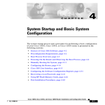
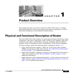
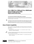
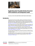
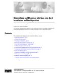
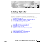
1
Cisco 12010, Cisco 12410, and Cisco 12810 Router
Clock and Scheduler, Switch Fabric, and Alarm
Card Replacement Instructions
Document Order Number: DOC-OL-13810-01, May 30, 2008
Product Numbers: 12010E-CSC=, 12410E-CSC=, 12410E-SFC, 12810E-CSC=, 12010-CSC, 12010-SFC, GSR10-CSC=,
GSR10-SFC=, 12810-CSC=, 12810-SFC=, GSR-ALRM=, GSR10-DISP=
This publication contains removal and installation procedures for the clock and scheduler card (CSC),
switch fabric card (SFC), alarm card, and the alarm card display on Cisco 12010, Cisco 12410, and
Cisco 12810 Routers. The CSC and SFC are a card set referred to as the switch fabric. The alarm card
is not a part of the switch fabric card set.
Also provided are procedures for upgrading from a 10-gigabit-per-second (Gbps) switch fabric to a
40-Gbps switch fabric. In addition, instructions for verifying the operation of the system after you
replace a card along with switch fabric troubleshooting information are also included.
Contents
•
Switch Fabric Overview, page 2
•
Alarm Card and Alarm Display Overview, page 4
•
Preparing for Installation, page 6
•
Removing and Installing a CSC or SFC, page 10
•
Removing and Installing the Alarm Card, page 15
•
Removing and Installing the External Alarm Display, page 18
•
Upgrading the Switch Fabric, page 19
•
Troubleshooting the Switch Fabric, page 22
•
Regulatory, Compliance, and Safety Information, page 27
•
Obtaining Documentation and Submitting a Service Request, page 30
Americas Headquarters:
Cisco Systems, Inc., 170 West Tasman Drive, San Jose, CA 95134-1706 USA
Switch Fabric Overview
Switch Fabric Overview
The switch fabric for the Cisco 12010, Cisco 12410, and Cisco 12810 Router consists of two clock and
scheduler cards (CSCs) and five switch fabric cards (SFCs) installed in the switch fabric and alarm card
cage. One CSC and four SFCs are required for an active switch fabric; the second CSC and the fifth SFC
provide redundancy.
Note
Two alarm cards are also located in the switch fabric and alarm card cage. These cards are not a part of
the switch fabric. However, their removal and installation procedures are located in this publication in
the “Removing and Installing the Alarm Card” section on page 15.
Figure 1 illustrates the switch fabric and alarm card cage with the air filter door open. The cards in the
switch fabric and alarm card cage are labeled CSC-200, SFC-200, and Alarm. The labeling that identifies
the type of card for each slot is viewable when the air filter door is open.
Figure 1
Switch Fabric and Alarm Card Cage
53277
E PROCESSOR
ST ETERNET
OC-12/STM-4 ATM
-48/STM-16-SCPOS
12DS3–SMB P/H/F
6DS3–SMB P/H/F
2
ALARM
C
SF
-3/STM-POS
Note
The CSCs and SFCs support online insertion and removal (OIR), which means you can remove and
install a card while the router remains powered on. On the 10-slot chassis, the CSC's are only used for
clocking purposes and do not carry any data traffic. There are 5 SFC cards which carry the traffic. 4 of
the SFCs carry the actual traffic, while the 5th SFC is for redundancy purposes in case one of the SFC's
fail. The recommended procedure for any fabric card removal is to perform a hw module shut command
on the card, wait for approximately 1 minute, and then remove the card. Primary CSC OIR results in
traffic loss regardless of the line cards installed in chassis. Redundant SFC or CSC OIR should not cause
traffic loss regardless of the line cards installed in chassis.
The Cisco 12010 Router supports a 2.5-Gbps switch fabric.The Cisco 12410 Router supports a 10-Gbps
switch fabric. The Cisco 12810 Router supports a 40-Gbps switch fabric. Each SFC or CSC provides
either a 2.5-, 10-, or 40-Gbps full-duplex connection to each line card in the system.
There are currently six switch fabric options:
•
Enhanced 2.5-Gbps switch fabric (50-Gbps switching system bandwidth) used in the Cisco 12010
Router—Consists of the 12010E-CSC and the 12010E-SFC fabric sets. Each SFC or CSC card
provides a 2.5-Gbps full-duplex connection to each line card in the system. Thus, for a Cisco 12010
Router with 10 line cards with 2 x 2.5 Gbps (full duplex), the system switching bandwidth is 10 x 5
Gbps = 50-Gbps. The enhanced fabric is required when enabling the Single-Router Automatic
Protection Switching (APS) or Building Integrated Timing Supply (BITS).
Cisco 12010, Cisco 12410, and Cisco 12810 Router Clock and Scheduler, Switch Fabric, and Alarm Card Replacement Instructions
2
OL-13810-01
Switch Fabric Overview
Note
•
Enhanced 10-Gbps switch fabric (200-Gbps switching system bandwidth) used in the Cisco 12410
Router—Consists of the 12410E-CSC and the 12410E-SFC fabric sets. Each SFC or CSC card
provides a 10-Gbps full-duplex connection to each line card in the system. Thus, for a Cisco 12410
Router with 10 line cards with 2 x 10 Gbps (full duplex), the system switching bandwidth is 10 x 20
Gbps = 200 Gbps. The enhanced fabric is required when enabling the Single-Router APS or BITS
features.
•
Enhanced 40-Gbps switch fabric (800-Gbps switching system bandwidth) used in the Cisco 12810
Router—Consists of the 12810E-CSC and the 12810-SFC fabric sets. Each SFC or CSC card
provides a 40-Gbps full-duplex connection to each line card in the system. Thus, for a Cisco 12810
Internet Router with 10 line cards with 2 x 40 Gbps (full duplex), the system switching bandwidth
is 10 x 80 Gbps = 800-Gbps. The enhanced fabric is required when enabling the Single-Router APS
or BITS features.
•
2.5-Gbps switch fabric (50-Gbps switching system bandwidth) used in the Cisco 12010
Router—Consists of the 12010-CSC and the 12010-SFC fabric sets. Each SFC or CSC card provides
a 2.5-Gbps full-duplex connection to each line card in the system. Thus, for a Cisco 12010 Router
with 10 line cards with 2 x 2.5 Gbps (full duplex), the system switching bandwidth is 10 x 5 Gbps
= 50 Gbps.
•
10-Gbps switch fabric (200-Gbps switching system bandwidth) used in the Cisco 12410
Router—Consists of the GSR10-CSC= and the GSR10-SFC= fabric sets. Each SFC or CSC card
provides a 10-Gbps full-duplex connection to each line card in the system. Thus, for a Cisco 12410
Router with 10 line cards with 2 x 10 Gbps (full duplex), the system switching bandwidth is 10 x 20
Gbps = 200 Gbps.
•
40-Gbps switch fabric (800-Gbps switching system bandwidth) used in the Cisco 12810
Router—Consists of the 12810-CSC= and the 12810-SFC= fabric sets. Each SFC or CSC card
provides a 40 Gbps full-duplex connection to each line card in the system. Thus, for a Cisco 12810
Internet Router with 10 line cards with 2 x 40 Gbps (full duplex), the system switching bandwidth
is 10 x 80 Gbps = 800 Gbps.
Although they perform similar functions, you cannot intermix SFCs and CSCs. The switch fabric is a
card set. You must use either the 2.5-, 10-, or 40-Gbps switch fabric card set. Also, the 10-Gbps switch
fabric does not operate in one-quarter bandwidth mode as did some earlier models of the
Cisco 12000 Series routers.
Switch Fabric Card Types
Your router ships from the factory with two CSCs and five SFCs installed in the nine slots in the switch
fabric and alarm card cage.
CSCs are installed in slot 0 or slot 1 (labeled CSC 0 or CSC 1); SFCs are installed in slots 2, 3, 4, 5, and
6. (labeled SFC 0, SFC 1, SFC 2, SFC 3, and SFC 4).
The CSC provides the following functionality:
•
Scheduler—Handles requests from the line cards for access to the switch fabric and determines
when to allow the line cards access to the switch fabric.
•
System clock—Sent to all SFCs, line cards, and the route processor (RP). The system clock
synchronizes data transfers between line cards or between line cards and the RP through the switch
fabric.
•
Switch fabric—Carries the user traffic between line cards or between the RP and a line card. The
switch fabric on the CSC is identical to the switch fabric on the SFC.
Cisco 12010, Cisco 12410, and Cisco 12810 Router Clock and Scheduler, Switch Fabric, and Alarm Card Replacement Instructions
OL-13810-01
3
Alarm Card and Alarm Display Overview
The SFC contains only the switch fabric circuitry, which carries user traffic between line cards or
between the RP and the line cards. The SFC receives scheduling information and the system clock sent
from the CSC.
LEDs on the faceplate of the external alarm display card display the status of the cards in the switch
fabric and alarm card cage. The alarm display card faceplate has one pair of LEDs for each of the nine
card slots (seven fabric cards and two alarm cards) in the switch fabric and alarm card cage.
Each pair of LEDs consists of a green LED labeled ENABLED and a yellow LED labeled FAIL. When
a green LED is on, the CSC or SFC in the corresponding slot is installed and operational. When the LED
is off, either the slot is empty or the card installed in the slot is faulty. When a yellow LED is on, the
router detects a fault on the card in the corresponding slot.
Switch Fabric Card Redundancy
On the 10-slot chassis, the CSC's are only used for clocking purposes and do not carry any data traffic.
There are 5 SFC cards which carry the traffic. 4 of the SFCs carry the actual traffic, while the 5th SFC
is for redundancy purposes in case one of the SFC's fail. The interfaces between the line cards and the
switch fabric are monitored constantly. If the system detects a loss of synchronization (LOS), it
automatically activates the data paths of the redundant SFC, and data flows across the redundant path.
The switch to the redundant CSC occurs within sub-seconds (the actual switch time depends on your
configuration and its scale).
Alarm Card and Alarm Display Overview
The router alarm and alarm display system consists of two alarm cards that are located in the switch
fabric and alarm card cage and an alarm display mounted on the front of the chassis below the blower
module (Figure 2).
Note
The two alarm cards located in the switch fabric and alarm card cage are not part of the switch fabric.
The switch fabric and alarm card cage is located behind the air filter door. The two alarm cards are
located in the two right-most slots, which are labeled Alarm, in the switch fabric and alarm card cage.
Cisco 12010, Cisco 12410, and Cisco 12810 Router Clock and Scheduler, Switch Fabric, and Alarm Card Replacement Instructions
4
OL-13810-01
Alarm Card and Alarm Display Overview
Figure 2
Alarm Cards and Alarm Display
Blower module
Alarm display
Line card and
GRP card cage
L
I
N
E
C
A
R
D
L
I
N
E
C
A
R
D
L
I
N
E
C
A
R
D
L
I
N
E
C
A
R
D
L
I
N
E
C
A
R
D
L
I
N
E
C
A
R
D
L
I
N
E
C
A
R
D
L
I
N
E
C
A
R
D
R
P
C
A
R
D
1
R
P
C
A
R
D
0
Slot Slot Slot Slot Slot Slot Slot Slot Slot Slot
0
1
2
3
4
5
6
7
8
9
C
S
C
1
S
F
C
0
S
F
C
1
S
F
C
2
PEM1
S
F
C
3
S
F
C
4
A
L
A
R
M
0
A
L
A
R
M
1
PEM2
50397
Switch fabric
and alarm
card cage
C
S
C
0
The alarm cards and alarm display perform four functions:
•
Hardware implementation of the alarm system
•
OK/FAIL status indication for the CSCs and SFCs
•
Power system monitoring
•
Redundant generation of the 5 VDC maintenance bus (MBus) supply voltage for the line cards
The display indicator LEDs, alarm relays, and external alarm relay connectors are located on a separate
card in order to accommodate the mechanical design requirements of the router enclosure. The external
alarm display assembly is mounted on the front of the chassis just above the horizontal
cable-management tray (Figure 3). The alarm display assembly is sometimes referred to as the alarm
display card or alarm display. The power system monitoring functions are located in the alarm card
MBus module.
Cisco 12010, Cisco 12410, and Cisco 12810 Router Clock and Scheduler, Switch Fabric, and Alarm Card Replacement Instructions
OL-13810-01
5
Preparing for Installation
Figure 3
External Alarm Display Assembly
Alarm display
MBUS
CSC
SFC
A
ALARM A
FAIL
B
ALARM B
R
MINO
R
MAJO
A
ICAL
CRIT
B
0
ENABLE
1
0
1
2
3
4
RA
CDHNT
CDHNT
LOOP
RA
DOWN
LOOP
DOWN
CD
CD
LA
LA
TX
TX
0
0
RX
RX
0
TX
TX
0
1
1
RX
RX
TX
TX
2
2
R
VE IE T
TI RR PK
AC CA RX
R
VE IE T
TI RR PK
AC CA RX
T
EC
EC
EJ
EJ
RX
RX
T
-1
OT
SL -0
OT
SL
TI
3
AC
3
-1
OT
SL -0
OT
SL
1
TX
TX
1
0
T
SE
X
AU
RE
X
AU
T
SE
RE
TX
TX
R
VE IE PKT
RR
CA RX
RX
RX
R
VE IE LL
TI RR CE
AC CA RX
4
4
RX
RX
R
VE IE T
TI RR PK
AC CA RX
R
VE IE T
TI RR PK
AC CA RX
TX
TX
2
5
2
5
RX
RX
E
OL
NS
CO
E
OL
NS
CO
TX
R
VE IE T
TI RR PK
AC CA RX
R
VE IE T
TI RR PK
AC CA RX
6
RX
TX
3
7
3
RX
TX
8
R
VE IE T
TI RR PK
AC CA RX
RX
K
LIN
LIN
R
VE IE T
TI RR PK
AC CA RX
K
TX
RX
LL
CO RX
LL
TX
CO
TX
9
RX
5
5
-4
RJ
10
-4
RJ
I
MI
I
MI
TX
RX
TX
53369
ROUTE PROCESSOR
ROUTE PROCESSOR
FAST ETERNET
P/H/F
OC-12/STM-4 ATM
RX12DS3–SMB
OC-48/STM-16-SCPOS
11
6DS3–SMB P/H/F
Q OC-3/STM-POS
Q OC-3/STM-POS
Preparing for Installation
Installation preparation is presented in the following sections:
•
Safety Guidelines
•
Preventing Electrostatic Discharge Damage
•
Required Tools and Equipment
•
Related Documentation
Safety Guidelines
Before you perform any procedure in this publication, review the safety guidelines in this section to
avoid injuring yourself or damaging the equipment. In addition, review the safety warnings listed in the
Regulatory Compliance and Safety Information for the Cisco 12000 Series Internet Router publication
that accompanied your router before installing, configuring, or maintaining the router.
The following guidelines are for your safety and to protect equipment. The guidelines do not include all
hazards. Be alert.
Safety with Equipment
•
Always disconnect all power cords and interface cables before moving the system.
•
Never assume that power is disconnected from a circuit; always check.
•
Keep tools and assembly components away from walk areas.
Cisco 12010, Cisco 12410, and Cisco 12810 Router Clock and Scheduler, Switch Fabric, and Alarm Card Replacement Instructions
6
OL-13810-01
Preparing for Installation
•
Do not work alone if potentially hazardous conditions exist.
•
Do not perform any action that creates a potential hazard to people or makes the equipment unsafe.
•
Carefully examine your work area for possible hazards such as moist floors, ungrounded power
extension cables, and missing safety grounds.
Safety with Electricity
•
Before beginning any procedures requiring access to the interior of the router, locate the emergency
power-off switch for the room in which you are working.
•
Disconnect all power and external cables before installing or removing a router.
•
Never assume that power has been disconnected from a circuit; always check.
•
Do not perform any action that creates a potential hazard to people or makes the equipment unsafe.
•
Never install equipment that appears damaged.
•
Carefully examine your work area for possible hazards such as moist floors, ungrounded power
extension cables, and missing safety grounds.
•
If an electrical accident does occur, proceed as follows:
– Use caution; do not become a victim yourself. Disconnect power to the router.
– If possible, send another person to get medical aid; otherwise, assess the condition of the victim
and then call for help.
– Determine if the person needs rescue breathing or external cardiac compressions; then take
appropriate action.
In addition, observe the following guidelines when working with any equipment that is disconnected
from a power source but still connected to telephone or network wiring:
•
Never install telephone wiring during a lightning storm.
•
Never install telephone jacks in wet locations unless the jack is specifically designed for wet
locations.
•
Never touch uninsulated telephone wires or terminals unless the telephone line has been
disconnected at the network interface.
•
Use caution when installing or modifying telephone lines.
Cisco 12010, Cisco 12410, and Cisco 12810 Router Clock and Scheduler, Switch Fabric, and Alarm Card Replacement Instructions
OL-13810-01
7
Preparing for Installation
Preventing Electrostatic Discharge Damage
Many router components can be damaged by static electricity. Some components can be damaged by
voltages as low as 30V, while static voltages as high as 35,000V can be generated just by handling plastic
or foam packing material, or by sliding assemblies across plastic and carpets. Not exercising the proper
electrostatic discharge (ESD) precautions can result in intermittent or complete component failures. To
minimize the potential for ESD damage, observe the following guidelines:
•
Caution
Always use an ESD-preventive antistatic wrist strap or ankle strap and ensure that it makes good
skin contact.
You should periodically check the resistance value of the ESD-preventive strap. The measurement
should be between 1 and 10 megohms.
•
When removing or installing a component, make sure the equipment end of your antistatic strap
leash is connected to one of the ESD connection sockets on the front of the chassis or to a bare metal
surface on the chassis (Figure 4). Avoid contact between the component and your clothing. The
ESD-preventive wrist strap only protects the component from ESD voltages on the body; ESD
voltages on your clothing can still cause component damage.
•
Always place a card component-side-up on an antistatic surface, in an antistatic card rack, or in a
static shielding bag. If you are returning the item to the factory, immediately place it in a static
shielding bag.
•
When installing a line card or route processor (RP), use the ejector levers to seat the card connectors
in the backplane, then tighten both captive screws on the faceplate of the card. These screws prevent
accidental removal, provide proper grounding for the router, and help to ensure that the card
connector is seated in the backplane.
•
When removing line cards, CSCs, SFCs, alarm cards, or an RP, use the ejector levers to unseat the
card connector from the backplane. Pull the metal card carrier out slowly, placing one hand along
the bottom of the carrier to guide it straight out of the slot.
•
Handle line cards, CSCs, SFCs, alarm cards, or an RP by the metal card carrier edges only; avoid
touching the board or any connector pins.
Cisco 12010, Cisco 12410, and Cisco 12810 Router Clock and Scheduler, Switch Fabric, and Alarm Card Replacement Instructions
8
OL-13810-01
Preparing for Installation
Figure 4
Connecting an ESD-Preventive Wrist Strap to the Chassis
ESD
connection
socket
MBUS
CSC
SFC
A
ALARM A
FAIL
B
ALARM B
R
MINO
R
MAJO
A
ICAL
CRIT
B
0
ENABLE
1
0
1
2
3
4
RA
CDHNT
CDHNT
LOOP
RA
DOWN
LOOP
DOWN
CD
CD
LA
LA
TX
TX
0
0
RX
RX
0
TX
TX
0
1
1
RX
RX
TX
TX
2
2
R
VE IE T
TI RR PK
AC CA RX
R
VE IE T
TI RR PK
AC CA RX
T
EC
EJ
EC
EJ
RX
RX
T
SE
T
X
AU
RE
T
X
AU
SE
RE
4
R
VE IE LL
TI RR CE
AC CA RX
O
0
TX
TX
R
VE IE PKT
RR
CA RX
RX
RX
4
RX
RX
R
VE IE T
TI RR PK
AC CA RX
R
VE IE T
TI RR PK
AC CA RX
TX
TX
2
5
2
5
RX
RX
NS
CO
E
OL
NS
CO
E
OL
TX
R
VE IE T
TI RR PK
AC CA RX
R
VE IE T
TI RR PK
AC CA RX
6
RX
TX
3
7
3
RX
TX
8
R
VE IE T
TI RR PK
AC CA RX
RX
K
LIN
LIN
R
VE IE T
TI RR PK
AC CA RX
K
TX
RX
LL
CO RX
LL
TX
CO
TX
9
RX
-4
RJ
-4
10
RJ
I
MI
I
MI
TX
5
5
RX
TX
53230
ROUTE PROCESSOR
ROUTE PROCESSOR
FAST ETERNET
OC-12/STM-4 ATM
P/H/F
6DS3–SMB P/H/F
RX12DS3–SMB
OC-48/STM-16-SCPOS
11
Q OC-3/STM-POS
Q OC-3/STM-POS
OOOOOOOOOOOOOOOOOOOOOOOOOOOOOOOOOOO
OOOOOO
OOOOOOOOO
OOOOO
OOOOOOO
O
O
O
O
O
OOOOO
OOO
OOOO
OOOOO
O
O
OOOO
O
O
OOOO
-1
OT
SL -0
OT
SL
TI
3
AC
3
-1
OT
SL -0
OT
SL
1
TX
TX
1
Required Tools and Equipment
The following tools and equipment are required to remove and install CSCs, SFCs, and the alarm card
and alarm display:
•
ESD-preventive wrist strap
•
Flat-blade screwdriver
Related Documentation
The following publications contain additional information:
•
Cisco 12010, Cisco 12410, and Cisco 12810 Router Installation and Configuration Guide
•
Regulatory Compliance and Safety Information for the Cisco 12000 Series Internet Router
Cisco 12010, Cisco 12410, and Cisco 12810 Router Clock and Scheduler, Switch Fabric, and Alarm Card Replacement Instructions
OL-13810-01
9
Removing and Installing a CSC or SFC
Removing and Installing a CSC or SFC
The switch fabric and alarm card cage is located below the line card and RP card cage, behind the air
filter door on the front of the chassis. (See Figure 5.) The switch fabric and alarm card cage has seven
keyed, vertical card slots for the clock and scheduler cards (CSCs) and switch fabric cards (SFCs). CSCs
are installed in the left two card slots (labeled CSC 0 and CSC 1); SFCs are installed in the next five slots
(labeled SFC 0, 1, 2, 3 and 4). Two alarm cards are installed in the right two card slots of the switch
fabric and alarm card cage, although they are not a part of the switch fabric.
Procedures for removing and installing a CSC or an SFC are described in the following sections:
•
Opening the Air Filter Door, page 10
•
Removing a Card from the Switch Fabric and Alarm Card Cage, page 11
•
Installing a Card in the Switch Fabric and Alarm Card Cage, page 13
•
Closing the Air Filter Door, page 13
Opening the Air Filter Door
To remove or install either a CSC or SFC, you must open the air filter door to gain access to the fabric
card cage. To access the fabric card cage, use Figure 5 as a reference and follow these steps:
Step 1
Attach an ESD-preventive wrist strap to your wrist and connect the leash to one of the ESD connection
sockets on the front of the chassis or to a bare metal surface on the chassis (see Figure 4 on page 9).
Step 2
Loosen the two captive screws on each side of the air filter door.
Step 3
Grasp the sides of the air filter door front cover and swing the door out and down, away from the switch
fabric and alarm card cage. The air filter door is attached to the chassis by a hinges on the bottom.
Caution
Be especially careful not to damage the honeycomb screen on the back of the air filter door and on the
inside of the switch fabric and alarm card cage. Damaging the honeycomb screen can restrict the air flow
and cause overheating in the router, and it can diminish EMI protection.
Cisco 12010, Cisco 12410, and Cisco 12810 Router Clock and Scheduler, Switch Fabric, and Alarm Card Replacement Instructions
10
OL-13810-01
Removing and Installing a CSC or SFC
Figure 5
Opening the Air Filter Door
53272
OCESSOR
PROCESSOR
E PROCESSOR
ST ETERNET
OC-12/STM-4 ATM
-48/STM-16-SCPOS
12DS3–SMB P/H/F
6DS3–SMB P/H/F
2
ALARM
C
SF
-3/STM-POS
Removing a Card from the Switch Fabric and Alarm Card Cage
To remove cards from the switch fabric and alarm card cage, use Figure 6 as a reference and follow these
steps:
Step 1
Attach an ESD-preventive wrist strap to your wrist and connect the leash to one of the ESD connection
sockets on the front of the chassis or to a bare metal surface on the chassis (see Figure 4 on page 9).
Step 2
Select one of the cards in the switch fabric and alarm card cage. Grasp the two card ejector levers and
simultaneously pivot both ejector levers 70 degrees away from the front edge of the card carrier to unseat
the card from the backplane connector.
Step 3
Touching only the metal card carrier, slide the card out of the slot and place it directly into an antistatic
bag or other ESD-preventive container.
Cisco 12010, Cisco 12410, and Cisco 12810 Router Clock and Scheduler, Switch Fabric, and Alarm Card Replacement Instructions
OL-13810-01
11
Removing and Installing a CSC or SFC
Figure 6
Removing a Card from the Switch Fabric and Alarm Card Cage
Clock scheduler card
53270
E PROCESSOR
ST ETERNET
OC-12/STM-4 ATM
-48/STM-16-SCPOS
12DS3–SMB P/H/F
6DS3–SMB P/H/F
2
C
ALARM
SF
-3/STM-POS
Air filter door
Cisco 12010, Cisco 12410, and Cisco 12810 Router Clock and Scheduler, Switch Fabric, and Alarm Card Replacement Instructions
12
OL-13810-01
Removing and Installing a CSC or SFC
Installing a Card in the Switch Fabric and Alarm Card Cage
To install a CSC or an SFC, follow these steps:
Step 1
Attach an ESD-preventive wrist strap to your wrist and connect the leash to one of the ESD sockets on
the front of the chassis or to a bare metal surface. (See Figure 4 on page 9.)
Step 2
Remove the replacement card from its antistatic bag or ESD-preventive container.
Step 3
Determine the assigned card slot for the card by checking the label attached to the edge of the card carrier
(near the bottom ejector lever). This will be the slot from which you just removed a CSC or an SFC.
Clock and scheduler cards are labeled CSC and are installed in the two far left slots; switch fabric cards
are labeled SFC and are installed in the next five slots. Alarm cards are installed in the last two slots.
Note
Alignment grooves exist on each slot in the switch fabric and alarm card cage. When you
reinstall a card in the switch fabric and alarm card cage, make sure you align the top and bottom
edges of the card carrier in the slot grooves.
Step 4
Grasp the card carrier handle with one hand and place your other hand under the carrier to support and
guide it into the correct slot. Slide the card halfway into the slot. Avoid touching the card circuitry or
any connectors.
Step 5
Pivot both card ejector levers so the openings on the card ejector cams at the top and bottom of the card
pass over the tabs on each side of the card cage slot.
Caution
Verify that the openings on the card ejector cams pass over the tabs; otherwise, one or both ejector levers
might bind when you attempt to close the ejector levers, damaging or breaking one or both ejector levers.
Step 6
Note
Continue sliding the card into the card cage slot until the openings on the card ejector cams
engage the tabs on each side of the card cage slot.
Note
CSCs and SFCs have guide pins that make initial contact with the backplane connector as you
slide a card into its slot. After the guide pins make contact, continue pushing on the card carrier
until the card ejector levers begin pivoting forward.
To seat the card in the backplane connector, grasp both card ejector levers and pivot them inward toward
the middle of the card carrier until they are flush against the front edge of the card carrier.
Closing the Air Filter Door
To close the air filter door, follow these steps:
Step 1
Grasp the sides of the air filter door front cover and pivot the air filter door up so that it is aligned with
the opening of the switch fabric and alarm card cage, and the two guide pins are inserted in the
corresponding holes on each side of the switch fabric and alarm card cage.
Cisco 12010, Cisco 12410, and Cisco 12810 Router Clock and Scheduler, Switch Fabric, and Alarm Card Replacement Instructions
OL-13810-01
13
Removing and Installing a CSC or SFC
Caution
All four sides of the air filter door are lined with EMI-preventive gaskets consisting of many raised,
conductive contacts. Align and seat the door carefully to avoid damaging the EMI-preventive gasket
contacts. A damaged gasket can result in reduced EMI performance.
Step 2
Push firmly on the air filter door until it is seated in the opening of the switch fabric and alarm card cage,
then tighten the two captive screws in each.
Caution
Be careful not to damage the honeycomb screen on the back of the air filter door and on the inside of the
switch fabric and alarm card cage. Damaging the honeycomb screen can restrict the air flow and cause
overheating in the router, and it can diminish EMI protection.
Cisco 12010, Cisco 12410, and Cisco 12810 Router Clock and Scheduler, Switch Fabric, and Alarm Card Replacement Instructions
14
OL-13810-01
Removing and Installing the Alarm Card
Removing and Installing the Alarm Card
Procedures for removing and installing the alarm card are described in the following sections:
•
Upgrading the Mbus ROM, page 15
•
Removing an Alarm Card, page 15
•
Installing an Alarm Card, page 17
Note
Caution
One alarm card can be replaced while the system is running, but you must do this quickly
because the normal cooling process is interrupted when the air filter door is open.
When an alarm card is installed or replaced, you must perform an upgrade to Mbus ROM agent
Version 3.46 (minimum). See the “Upgrading the Mbus ROM” section that follows.
Upgrading the Mbus ROM
The MBus agent ROM firmware is bundled with the Cisco IOS software. You must upgrade the MBus
agent ROM firmware on the GRP card or line cards if your MBus agent ROM firmware is a random
number (for example, FF.DE), or if it is not the currently released version (the current version is 1.33).
To upgrade the MBus firmware on one or more line cards, perform the following tasks in privileged
EXEC mode.
Step 1
Check the current MBus agent software version using the show diag [slot-number] command.
Step 2
Upgrade the MBus agent software on a specific line card using the upgrade mbus-agent-rom
[slot-number] command.
Step 3
Upgrade the MBus agent software on all line cards using the upgrade mbus-agent-rom all command.
Step 4
Verify that there is a new MBus agent software version using the show diag [slot-number] command for
each line card.
Removing an Alarm Card
To remove an alarm card, follow these steps:
Step 1
Attach an ESD-preventive wrist strap to your wrist and connect the leash to one of the ESD connection
sockets on the front of the chassis or to a bare metal surface on the chassis (see Figure 4 on page 9).
Step 2
Loosen the captive screws (one on each side of the air filter door) that fasten the air filter door to the
chassis (Figure 7).
Cisco 12010, Cisco 12410, and Cisco 12810 Router Clock and Scheduler, Switch Fabric, and Alarm Card Replacement Instructions
OL-13810-01
15
Removing and Installing the Alarm Card
Figure 7
Opening the Chassis Air Filter Door
53272
OCESSOR
PROCESSOR
E PROCESSOR
ST ETERNET
OC-12/STM-4 ATM
-48/STM-16-SCPOS
12DS3–SMB P/H/F
6DS3–SMB P/H/F
2
ALARM
C
SF
-3/STM-POS
Cisco 12010, Cisco 12410, and Cisco 12810 Router Clock and Scheduler, Switch Fabric, and Alarm Card Replacement Instructions
16
OL-13810-01
Removing and Installing the Alarm Card
Step 3
Grasp the sides of the air filter door front cover and carefully pivot the door down, away from the switch
fabric and alarm card cage (Figure 8).
The alarm cards are the two right-most cards in the switch fabric and alarm card cage. They are labeled
Alarm.
Figure 8
Switch Fabric and Alarm Card Cage (Door Open)
53277
E PROCESSOR
ST ETERNET
OC-12/STM-4 ATM
-48/STM-16-SCPOS
12DS3–SMB P/H/F
6DS3–SMB P/H/F
2
ALARM
C
SF
-3/STM-POS
Step 4
Select the appropriate alarm cards in the switch fabric and alarm card cage. Grasp the two card ejector
levers and simultaneously pivot both ejector levers 70 degrees away from the front edge of the card
carrier to unseat the card from the backplane connector.
Step 5
Touching only the metal card carrier, slide the alarm card out of the slot and place it directly into an
antistatic sack or other ESD-preventive container.
Installing an Alarm Card
To replace an alarm card in the switch fabric and alarm card cage, follow these steps:
Step 1
Attach an ESD-preventive wrist strap to your wrist and connect the leash to one of the ESD sockets on
the front of the chassis or to a bare metal surface (see Figure 4 on page 9).
Step 2
Remove the replacement alarm card from its antistatic sack or ESD-preventive container.
Step 3
Determine the assigned card slot for the card by checking the label attached to the edge of the card carrier
(near the bottom ejector lever).
Note
There are alignment grooves on each slot in the switch fabric and alarm card cage. When you
reinstall a card in the switch fabric and alarm card cage, make sure you align the top and bottom
edges of the card carrier in the slot grooves.
Step 4
Grasp the card carrier handle with one hand and place your other hand under the carrier to support and
guide it into the correct slot. Slide the card halfway into the slot. Avoid touching the card circuitry or
any connectors.
Step 5
Pivot both card ejector levers so the openings on the card ejector cams at the top and bottom of the card
pass over the tabs on each side of the card cage slot.
Cisco 12010, Cisco 12410, and Cisco 12810 Router Clock and Scheduler, Switch Fabric, and Alarm Card Replacement Instructions
OL-13810-01
17
Removing and Installing the External Alarm Display
Caution
Verify that the openings on the card ejector cams pass over the tabs; otherwise, one or both ejector levers
might bind when you attempt to close the ejector levers, damaging or breaking one or both ejector levers.
Step 6
Continue sliding the card into the card cage slot until the openings on the card ejector cams engage the
tabs on each side of the card cage slot.
Step 7
To seat the card in the backplane connector, grasp both card ejector levers and pivot them inward toward
the middle of the card carrier until they are flush against the front edge of the card carrier.
Step 8
Pivot the air filter door up so that it is aligned with the opening of the switch fabric and alarm card cage.
Step 9
Secure the air filter door to the chassis with the two panel screws in the upper corners.
Caution
Mbus ROM upgrade must be performed when an alarm card is installed or replaced.
Removing and Installing the External Alarm Display
Procedures for removing and installing the external alarm display are described in the following
sections:
•
Removing the External Alarm Display, page 18
•
Installing the External Alarm Display, page 19
Removing the External Alarm Display
To replace the external alarm display assembly, follow these steps:
Step 1
Attach an ESD-preventive wrist strap to your wrist and connect the leash to one of the ESD sockets on
the front of the chassis or to a bare metal surface. (See Figure 4 on page 9.)
Step 2
If there are any external alarm cables connected to the ALARM A or ALARM B connectors, remove
them.
Step 3
Loosen the two screws that secure the cable that comes out of the chassis and attaches to the alarm
display assembly input connector.
Step 4
Disconnect the connector.
Step 5
Loosen the two panel screws, one on each side of the alarm display assembly, and remove the alarm
display assembly.
Cisco 12010, Cisco 12410, and Cisco 12810 Router Clock and Scheduler, Switch Fabric, and Alarm Card Replacement Instructions
18
OL-13810-01
Upgrading the Switch Fabric
Installing the External Alarm Display
To replace an external alarm display assembly, follow these steps:
Step 1
Attach an ESD-preventive wrist strap to your wrist and connect the leash to one of the ESD sockets on
the front of the chassis or to a bare metal surface (see Figure 4 on page 9).
Step 2
Secure the replacement external alarm display assembly to the chassis with the two panel screws.
Step 3
Connect the cable coming out of the chassis to the alarm display assembly INPUT connector and secure
the two screws in the cable.
Step 4
Connect any cables that were attached to the ALARM A or ALARM B connectors.
Upgrading the Switch Fabric
The switch fabric on the Cisco 12410 Router can be upgraded in the field to a Cisco 12810 Router. This
allows you to upgrade the 10-Gbps switch fabric to a 40-Gbps switch fabric. Table 1 lists Cisco router
model numbers, their corresponding switch fabric speed, and the available upgrade path for each router
model.
Table 1
Switch Fabric Upgrade Paths
Router Model
Switch Fabric Speed
Cisco 12010 Router
2.5 Gbps
Upgrade Path
•
Cisco 12410 Router
or
•
Cisco 12810 Router
Cisco 12410 Router
10 Gbps
Cisco 12810 Router
Cisco 12810 Router
40 Gbps
N/A
Cisco 12010, Cisco 12410, and Cisco 12810 Router Clock and Scheduler, Switch Fabric, and Alarm Card Replacement Instructions
OL-13810-01
19
Upgrading the Switch Fabric
Upgrade Requirements
Before proceeding, review the following upgrade requirements:
1.
You must have a complete switch fabric card set. You cannot intermix 2.5-, 10-, and 40-Gbps CSCs
and SFCs.
2.
When upgrading to a 10-Gbps switch fabric with a GRP installed, the Flash memory card must be
loaded with Cisco IOS Release 12.0(16)S or later.
3.
When upgrading to a 10-Gbps switch fabric with a PRP installed, the Flash memory card must be
loaded with Cisco IOS Release 12.0(22)S or later.
4.
When upgrading to a 40-Gbps switch fabric, the Performance Route Processor (PRP) must be
installed, and the flash memory card must be loaded with Cisco IOS Release 12.0(31)S or later.
5.
When upgrading to an enhanced 10-Gbps switch fabric, the Performance Route Processor (PRP)
must be installed, and the flash memory card must be loaded with Cisco IOS 12.0(32)SY2 or later.
6.
When upgrading to an enhanced 40-Gbps switch fabric, the Performance Route Processor (PRP)
must be installed, and the flash memory card must be loaded with Cisco IOS 12.0(31)S or later.
Upgrading the Switch Fabric
To upgrade the switch fabric, follow these steps:
Step 1
Turn off power to the router.
Step 2
Remove all CSCs and SFCs. See the “Removing a Card from the Switch Fabric and Alarm Card Cage”
section on page 11.
Step 3
Install the new CSCs and SFCs. See the “Installing a Card in the Switch Fabric and Alarm Card Cage”
section on page 13.
Note
Although they perform similar functions, you cannot intermix SFCs and CSCs. The switch fabric
is a card set. You must use either the 10- or 40-Gbps switch fabric card set.
Step 4
Insert a Flash memory card into the PRP, making sure that it is loaded with the appropriate
Cisco IOS release, noted in the “Upgrade Requirements” section on page 20.
Step 5
Turn on power to the router and wait for all installed line cards to fully boot before proceeding to the
next step.
Note
Let the router return to full operation before proceeding to the next step. This may take a
considerable amount of time depending upon the configuration of the router.
Step 6
At the privileged EXEC prompt, enter the configure terminal command to enter global configuration
mode.
Step 7
Enter the service upgrade mbus-agent-rom command.
Step 8
Enter the service upgrade fabric-downloader command.
Step 9
After the commands have finished running, press Ctrl-Z to exit configuration mode.
Cisco 12010, Cisco 12410, and Cisco 12810 Router Clock and Scheduler, Switch Fabric, and Alarm Card Replacement Instructions
20
OL-13810-01
Upgrading the Switch Fabric
Step 10
Note
See the next section, Verifying the Upgrade.
Additional information is available on the Cisco TAC website. Refer to the Cisco 12000 Series Internet
Router Upgrade Procedure document.
Verifying the Upgrade
To verify that the upgraded switch fabric is operating properly, follow these steps:
Step 1
Perform all the steps listed in the “Upgrading the Switch Fabric” section on page 19. If there is a
mismatch between the older and newer switch fabric cards, an error message appears on the console.
Step 2
Run the show gsr command to see if the new switch fabric cards are detected by the system.
Note
Step 3
The show gsr command output varies slightly between each switch fabric card set.
See the “Troubleshooting the Switch Fabric” section on page 22 if you encounter problems. Also review
the next section, Post-Upgrade Considerations.
Cisco 12010, Cisco 12410, and Cisco 12810 Router Clock and Scheduler, Switch Fabric, and Alarm Card Replacement Instructions
OL-13810-01
21
Troubleshooting the Switch Fabric
Post-Upgrade Considerations
After performing an upgrade and verifying its installation, there are some post-upgrade considerations.
•
Cisco 12000 Series routers include a label on the side of the chassis that indicates the model of the
router. The switch fabric upgrade kit does not include a new label to identify the upgraded router
model. For example, if you upgrade a Cisco 12410 Router to a Cisco 12810 Router, the label on the
side of the chassis still identifies the chassis as a Cisco 12410 Router. Cisco recommends that you
take the necessary administrative steps to properly identify an upgraded router.
•
The alternative methods for identifying an upgraded router are through the label on the switch fabric
cards or through Cisco IOS software, using the show gsr command. Table 2 lists the router model
and the number on the corresponding switch fabric card identification labels.
Table 2
Identifying Switch Fabric Cards
Router Model
Switch Fabric Card Identification Label
Cisco 12010 Router
SFC-50 and CSC-50
Cisco 12410 Router
SFC-200 & CSC-200
Cisco 12810 Router
SFC-800 & CSC-800
Troubleshooting the Switch Fabric
This section describes the procedures needed to troubleshoot problems with the switch fabric. The RP
and the line cards connect through the crossbar switch fabric, which provides a high-speed physical path
for most inter-card communication. Among the messages passed between the RP and the line cards over
the switch fabric are, actual packets being routed and received, forwarding information, traffic statistics,
and most management and control information. This information is useful in diagnosing
hardware-related failures.
Note
This section is recommended only for advanced Cisco IOS software operators and system administration
personnel. Refer to the appropriate Cisco IOS software publications for detailed Cisco IOS information.
To troubleshoot the switch fabric, follow these steps:
Step 1
Collect the needed data from the RPs and line cards.
Note
When you connect to the line card, use the attach command. The execute-on command is
dependent upon the inter-process communication (IPC) which operates over the switch fabric.
If you are having problems with IPC, the commands that run remotely through the switch fabric
can time out. The attach <slot #> command travels over the MBus and not the IPC.
Step 2
Use the show controllers fia command on the primary and secondary RPs and save the output.
Step 3
Use the attach <slot #> command to access a line card.
Step 4
Use the show controllers fia command on all installed line cards and save the output from each.
Cisco 12010, Cisco 12410, and Cisco 12810 Router Clock and Scheduler, Switch Fabric, and Alarm Card Replacement Instructions
22
OL-13810-01
Troubleshooting the Switch Fabric
Step 5
Gather the output and proceed to the Analyzing the Data section.
Analyzing the Data
Switch fabric problems can occur due to failures in any of the following components:
•
RP
•
Line card hardware
•
Backplane
•
CSCs/SFCs
When troubleshooting switch fabric errors, you need to look for patterns with regard to which
components are reporting errors. For example, if you combine the show controllers fia output from all
the RPs and line cards, you can determine if there is an error pattern. The following subsections discuss
the values within the output that can help you determine any error patterns.
Note
The sample output in this section comes from a Cisco 12016 Router. The main difference in these
examples, is that only three SFCs are shown in the output instead of five SFCs that are in the
Cisco 12010, Cisco 12410, and Cisco 12810 Routers.
crc16 Output
The crc16 data line from the show controllers fia command is an important indicator of hardware
problems. If online card or one CSC/SFC has been on line inserted and removed, you can expect to see
some crc16 error data. However, this number should not continue to increase. If the number increases,
you may need to replace some faulty hardware. It is important to correlate the data from both the primary
RP and the secondary RP and all installed line cards. The sample output below shows the status of the
primary RP. The crc16 data line is underlined and shows errors from sfc1.
Router#show controllers fia
Fabric configuration: Full bandwidth, redundant fabric
Master Scheduler: Slot 17 Backup Scheduler: Slot 16
From Fabric FIA Errors
----------------------redund fifo parity 0
redund overflow 0
cell drops 0
crc32 lkup parity 0
cell parity
0
crc32
0
Switch cards present
0x001F
Slots 16 17 18 19 20
Switch cards monitored 0x001F
Slots 16 17 18 19 20
Slot:
16
17
18
19
20
Name:
csc0
csc1
sfc0
sfc1
sfc2
-----------------------------------los
0
0
0
0
0
state Off
Off
Off
Off
Off
crc16 0
0
0
1345
0
To Fabric FIA Errors
----------------------sca not pres 0
req error
0
uni FIFO overflow
grant parity 0
multi req
0
uni FIFO undrflow
cntrl parity 0
uni req
0
crc32 lkup parity
multi FIFO
0
empty dst req 0
handshake error
cell parity 0
0
0
0
0
Cisco 12010, Cisco 12410, and Cisco 12810 Router Clock and Scheduler, Switch Fabric, and Alarm Card Replacement Instructions
OL-13810-01
23
Troubleshooting the Switch Fabric
In the sample output below, you can see the status of the line card in slot 2. The crc16 data line is
underlined and is showing errors from sfc1. Remember to use the attach command (not the execute-on
command) to access the line cards.
Router#attach 2
Entering Console for 4 port ATM Over SONET OC-3c/STM-1 in Slot: 2
Type "exit" to end this session
Press RETURN to get started!
LC-Slot2>
LC-Slot2>enable
LC-Slot2#show controllers fia
From Fabric FIA Errors
----------------------redund FIFO parity 0
redund overflow 0
cell drops 0
crc32 lkup parity 0
cell parity
0
crc32
0
Switch cards present
0x001F
Slots 16 17 18 19 20
Switch cards monitored 0x001F
Slots 16 17 18 19 20
Slot:
16
17
18
19
20
Name:
csc0
csc1
sfc0
sfc1
sfc2
-----------------------------------Los
0
0
0
0
0
state Off
Off
Off
Off
Off
crc16 0
0
0
1345
0
To Fabric FIA Errors
----------------------sca not pres 0
req error
0
uni fifo overflow 0
grant parity 0
multi req
0
uni fifo undrflow 0
cntrl parity 0
uni req
0
crc32 lkup parity 0
multi fifo
0
empty DST req 0
handshake error
0
cell parity 0
LC-Slot2#exit
Disconnecting from slot 2.
Connection Duration: 00:00:21
Router#
After you gather the show controllers fia command data from the RPs and line cards, you can create a
table similar to Table 3.
Table 3
Card Slot
0
Error Data Collection Table
CSC 0
CSC 1
SFC 0
SFC 1
SFC 2
SFC 3
SFC 4
ERROR
1
2
ERROR
3
ERROR
4
5
ERROR
6
7
ERROR
8
Cisco 12010, Cisco 12410, and Cisco 12810 Router Clock and Scheduler, Switch Fabric, and Alarm Card Replacement Instructions
24
OL-13810-01
Troubleshooting the Switch Fabric
This table indicates that more than one line card is reporting errors coming from SFC 1. Therefore, the
first step is to change this SFC. Each time a replacement is recommended, first verify that the card is
correctly seated. You should always reseat the corresponding card to ensure it is correctly seated. If, after
reseating the card, the CRCs still increase, then replace the part. See the “Properly Seating Switch Fabric
Cards” section on page 26.
The common failure patterns and recommended actions for crc16 errors are as follows (one step at a time
until the problem is eliminated):
1.
Errors indicated on more than one line card from the same switch fabric card:
a. Replace the switch fabric card in the slot corresponding to the errors
b. Replace all switch fabric cards
c. Replace the backplane
2.
Errors indicated on one line card from more than one switch fabric card:
a. Replace the line card
b. If errors are incrementing, replace the current master CSC
c. If errors are not incrementing and the current master is CSC0, replace CSC1
Grant Parity and Request Errors
Troubleshooting indicators include the console logs (or the output of the show log command) in the form
of grant parity and request errors. Look for the following type of message that indicates a grant parity
error:
%FABRIC-3-PARITYERR: To Fabric parity error was detected.
Grant parity error Data = 0x2.
SLOT 1:%FABRIC-3-PARITYERR: To Fabric parity error was detected.
Grant parity error Data = 0x1
You can also use the output from the show controllers fia command. Important information is
underlined:
Router#show controllers fia
Fabric configuration: Full bandwidth, redundant fabric
Master Scheduler: Slot 17
Backup Scheduler: Slot 16
From Fabric FIA Errors
----------------------redund FIFO parity 0
redund overflow 0
crc32 lkup parity 0
cell parity 0
Switch cards present
0x001F
Slots
Switch cards monitored 0x001F
Slots
Slot:
16
17
18
Name:
csc0
csc1
sfc0
---------------------Los
0
0
0
state Off
Off
Off
crc16 876
257
876
To Fabric FIA Errors
----------------------sca not pres 0
req error
grant parity 1
multi req
1
0
cell drops 76
crc32 0
16 17 18 19 20
16 17 18 19 20
19
20
sfc1
sfc2
--------------0
0
Off
Off
876
876
uni fifo overflow 0
uni fifo undrflow 0
Cisco 12010, Cisco 12410, and Cisco 12810 Router Clock and Scheduler, Switch Fabric, and Alarm Card Replacement Instructions
OL-13810-01
25
Troubleshooting the Switch Fabric
cntrl parity 0
multi fifo
0
cell parity 0
uni req
0
empty DST req 0
crc32 lkup parity 0
handshake error
0
The common failure patterns and recommended actions for grant parity and request errors are as follows
(one step at a time until the problem goes away):
1.
Grant errors on more than one line card:
a. Replace the CSC (see the note below to know which one should be swapped)
b. Replace the backplane
2.
Grant errors on one line card:
a. Replace the line card
a. Replace the CSC (see the note below to know which one should be swapped)
b. Replace the backplane
Note
If multiple line cards are reporting grant parity or request errors and the router is still
functioning, then a CSC switch-over has occurred. The failed CSC is the one that is currently
the backup CSC (not the one listed as Master Scheduler in the show controllers fia output). If
Halted appears next to the heading From Fabric FIA Errors or To Fabric FIA Errors, or if the
router is no longer forwarding traffic, then a CSC switch-over did not occur and the failing CSC
is listed as Master Scheduler. By default, the CSC in slot 17 is the primary and the CSC in slot
16 is the backup.
Properly Seating Switch Fabric Cards
The switch fabric cards in the router can be challenging to insert, and may require a small amount of
force to seat correctly. If either of the CSCs are not seated properly, you may see the following error
messages:
%MBUS-0-NOCSC: Must have at least 1 CSC card in slot 16 or 17
%MBUS-0-FABINIT: Failed to initialize switch fabric infrastructure
Note
You may also get this error message if there are only enough CSCs and SFCs seated for quarter
bandwidth configurations. Quarter bandwidth configurations are no longer supported on
Cisco 12000 Series routers.
When managing switch fabric and line card booting problems, it is important to verify that all CSCs and
SFCs are correctly seated and powered on. The output from the show version and show controllers fia
commands tells you which hardware configuration is currently running on the box. Important data is
underlined.
Router#show version
Cisco Internetwork Operating System Software
IOS (tm) GS Software (GSR-P-M), Experimental Version 12.0(20010505:112551)
Copyright (c) 1986-2001 by cisco Systems, Inc.
Compiled Mon 14-May-01 19:25 by tmcclure
Image text-base: 0x60010950, data-base: 0x61BE6000
ROM: System Bootstrap, Version 11.2(17)GS2, [htseng 180]
EARLY DEPLOYMENT RELEASE SOFTWARE (fc1)
BOOTFLASH: GS Software (GSR-BOOT-M), Version 12.0(15.6)S,
EARLY DEPLOYMENT MAINTENANCE INTERIM SOFTWARE
Cisco 12010, Cisco 12410, and Cisco 12810 Router Clock and Scheduler, Switch Fabric, and Alarm Card Replacement Instructions
26
OL-13810-01
Regulatory, Compliance, and Safety Information
Router
System
System
System
uptime is 17 hours, 53 minutes
returned to ROM by reload at 23:59:40 MET Mon Jul 2 2001
restarted at 00:01:30 MET Tue Jul 3 2001
image file is "tftp://172.17.247.195/gsr-p-mz.15S2plus-FT-14-May-2001"
cisco 12016/GRP (R5000) processor (revision 0x01) with 262144K bytes of memory.
R5000 CPU at 200Mhz, Implementation 35, Rev 2.1, 512KB L2 Cache
Last reset from power-on
2 Route Processor Cards
1 Clock Scheduler Card
3 Switch Fabric Cards
1 8-port OC3 POS controller (8 POs).
1 OC12 POS controller (1 POs).
1 OC48 POS E.D. controller (1 POs).
7 OC48 POS controllers (7 POs).
1 Ethernet/IEEE 802.3 interface(s)
17 Packet over SONET network interface(s)
507K bytes of non-volatile configuration memory.
20480K bytes of Flash PCMCIA card at slot 0 (Sector size 128K).
8192K bytes of Flash internal SIMM (Sector size 256K).
Router#show controller fia
Fabric configuration: Full bandwidth nonredundant
Master Scheduler: Slot 17
Additional troubleshooting information is available on Cisco.com.
Regulatory, Compliance, and Safety Information
This section includes regulatory, compliance, and safety information in the following sections:
•
Translated Safety Warnings and Agency Approvals
•
Electromagnetic Compatibility Regulatory Statements
Translated Safety Warnings and Agency Approvals
The complete list of translated safety warnings and agency approvals is available in the Regulatory
Compliance and Safety Information for Cisco 12000 Series Internet Routers publication.
(Document Number 78-4347-xx.)
Electromagnetic Compatibility Regulatory Statements
FCC Class B Compliance
The equipment described in this manual generates and may radiate radio-frequency energy. If it is not
installed in accordance with Cisco’s installation instructions, it may cause interference with radio and
television reception. This equipment has been tested and found to comply with the limits for a Class B
digital device in accordance with the specifications in part 15 of the FCC rules. These specifications are
designed to provide reasonable protection against such interference in a residential installation.
However, there is no guarantee that interference will not occur in a particular installation.
Cisco 12010, Cisco 12410, and Cisco 12810 Router Clock and Scheduler, Switch Fabric, and Alarm Card Replacement Instructions
OL-13810-01
27
Regulatory, Compliance, and Safety Information
Modifying the equipment without Cisco’s written authorization may result in the equipment no longer
complying with FCC requirements for Class B digital devices. In that event, your right to use the
equipment may be limited by FCC regulations, and you may be required to correct any interference to
radio or television communications at your own expense.
You can determine whether your equipment is causing interference by turning it off. If the interference
stops, it was probably caused by the Cisco equipment or one of its peripheral devices. If the equipment
causes interference to radio or television reception, try to correct the interference by using one or more
of the following measures:
• Turn the television or radio antenna until the interference stops.
• Move the equipment to one side or the other of the television or radio.
• Move the equipment farther away from the television or radio.
• Plug the equipment into an outlet that is on a different circuit from the television or radio. (That is,
make certain the equipment and the television or radio are on circuits controlled by different circuit
breakers or fuses.)
CISPR 22
This apparatus complies with CISPR 22/EN55022 Class B radiated and conducted emissions
requirements.
Canada
English Statement of Compliance
This class A digital apparatus complies with Canadian ICES-003.
French Statement of Compliance
Cet appareil numérique de la classe A est conforme à la norme NMB-003 du Canada.
Europe (EU)
This apparatus complies with EN55022 Class B and EN55024 standards when used as ITE/TTE
equipment, and EN300386 for Telecommunications Network Equipment (TNE) in both installation
environments, telecommunication centers and other indoor locations.
Cisco 12010, Cisco 12410, and Cisco 12810 Router Clock and Scheduler, Switch Fabric, and Alarm Card Replacement Instructions
28
OL-13810-01
Regulatory, Compliance, and Safety Information
VCCI Class A Notice for Japan
Warning
This is a Class A product based on the standard of the Voluntary Control Council
for Interference by Information Technology Equipment (VCCI). If this equipment
is used in a domestic environment, radio disturbance may arise. When such
trouble occurs, the user may be required to take corrective actions.
Statement 191
Class A Notice for Hungary
Warning
This equipment is a class A product and should be used and installed properly
according to the Hungarian EMC Class A requirements (MSZEN55022). Class A
equipment is designed for typical commercial establishments for which special
conditions of installation and protection distance are used. Statement 256
Class A Notice for Taiwan and Other Traditional Chinese Markets
Warning
This is a Class A Information Product, when used in residential environment, it
may cause radio frequency interference, under such circumstances, the user
may be requested to take appropriate countermeasures. Statement 257
Cisco 12010, Cisco 12410, and Cisco 12810 Router Clock and Scheduler, Switch Fabric, and Alarm Card Replacement Instructions
OL-13810-01
29
Regulatory, Compliance, and Safety Information
Class A Notice for Korea
Warning
This is a Class A Device and is registered for EMC requirements for industrial
use. The seller or buyer should be aware of this. If this type was sold or
purchased by mistake, it should be replaced with a residential-use type.
Statement 294
Obtaining Documentation and Submitting a Service Request
For information on obtaining documentation, submitting a service request, and gathering additional
information, see the monthly What’s New in Cisco Product Documentation, which also lists all new and
revised Cisco technical documentation, at:
http://www.cisco.com/en/US/docs/general/whatsnew/whatsnew.html
Subscribe to the What’s New in Cisco Product Documentation as a Really Simple Syndication (RSS) feed
and set content to be delivered directly to your desktop using a reader application. The RSS feeds are a free
service and Cisco currently supports RSS Version 2.0.
CCDE, CCENT, CCSI, Cisco Eos, Cisco HealthPresence, Cisco IronPort, the Cisco logo, Cisco Lumin, Cisco Nexus, Cisco Nurse Connect,
Cisco Pulse, Cisco StackPower, Cisco StadiumVision, Cisco TelePresence, Cisco Unified Computing System, Cisco WebEx, DCE, Flip Channels,
Flip for Good, Flip Mino, Flipshare (Design), Flip Ultra, Flip Video, Flip Video (Design), Instant Broadband, and Welcome to the Human Network
are trademarks; Changing the Way We Work, Live, Play, and Learn, Cisco Capital, Cisco Capital (Design), Cisco:Financed (Stylized), Cisco Store,
and Flip Gift Card are service marks; and Access Registrar, Aironet, AllTouch, AsyncOS, Bringing the Meeting To You, Catalyst, CCDA, CCDP,
CCIE, CCIP, CCNA, CCNP, CCSP, CCVP, Cisco, the Cisco Certified Internetwork Expert logo, Cisco IOS, Cisco Press, Cisco Systems,
Cisco Systems Capital, the Cisco Systems logo, Cisco Unity, Collaboration Without Limitation, Continuum, EtherFast, EtherSwitch, Event Center,
Explorer, Fast Step, Follow Me Browsing, FormShare, GainMaker, GigaDrive, HomeLink, iLYNX, Internet Quotient, IOS, iPhone, iQuick Study,
IronPort, the IronPort logo, Laser Link, LightStream, Linksys, MediaTone, MeetingPlace, MeetingPlace Chime Sound, MGX, Networkers,
Networking Academy, Network Registrar, PCNow, PIX, PowerKEY, PowerPanels, PowerTV, PowerTV (Design), PowerVu, Prisma, ProConnect,
ROSA, ScriptShare, SenderBase, SMARTnet, Spectrum Expert, StackWise, The Fastest Way to Increase Your Internet Quotient, TransPath, WebEx,
and the WebEx logo are registered trademarks of Cisco Systems, Inc. and/or its affiliates in the United States and certain other countries.
All other trademarks mentioned in this document or website are the property of their respective owners. The use of the word partner does not imply
a partnership relationship between Cisco and any other company. (0908R)
© 2009 Cisco Systems, Inc. All rights reserved.
Cisco 12010, Cisco 12410, and Cisco 12810 Router Clock and Scheduler, Switch Fabric, and Alarm Card Replacement Instructions
30
OL-13810-01