1
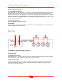
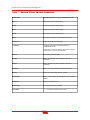
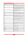
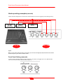
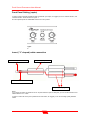
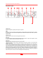
Sound Processor
USER MANUAL
www.proelgroup.com
Designed and Engineered by Proel UK
Proel Sound Processors User Manual
SAFETY INSTRUCTIONS
In order to avoid damage to unit hardware and electronic parts, during unit use and/or maintenance, following safety instructions must be
heed. Before using the unit, please read these instructions. Follow all instructions and keep this instruction manual.
- Be careful that unit operation may not cause damage to people.
- Place the unit in a location protected from weather and far from water and moisture.
- Don’t place this unit close to heat sources (radiators, spots, amplifiers etc.).
- Avoid any liquid entering inside the unit.
- Connect this unit to a power supply line able to support unit power consumption, checking power supply line good operating conditions.
- Be careful that power supply line has an efficient ground line.
- Disconnect the unit from a. c. power socket during lighting storms or when unused for long periods of time.
Refer all servicing to qualified service personnel. Servicing is required when the apparatus has been damaged in any way, such as:
- Detective connections and/or on connections cables.
- Liquid has spilled inside the unit.
- The unit has fallen or has been damager or doesn’t operate normally.
No user-serviceable parts inside. Refer servicing to an authorized maintenance centre.
Proel Sound Processor units comply with EMC Directive 89/336/CEE (Directive on approximation of member nation's ordinance
concerning the electromagnetic compatibility) and following modifications 92/31/CEE and 93/68/CEE, as stated in EN 50082-1:1997, EN
55013:1990, EN 55020:1994 standards. These units comply to Low Voltage Directive 73/23/EEC (Directive on approximation of member
nation's ordinance concerning electric equipment designed to be used within the specified voltage range), and following modifications
93/68/CEE, as stated in EN 60065:1998 standard.
To avoid electric shock don’t open this unit. To prevent risks of fire and/or electric shock, don’t expose this unit to rain or moisture.
PACKAGING
This unit package has been submitted to ISTA 1A integrity tests. We suggest you control the unit conditions immediately after unpacking
it. If any damage is found, immediately advise the dealer. Keep all unit packaging parts to allow inspection. Proel is not responsible for any
damage that occurs during shipment.
SHIPMENT AND COMPLAINT
Products are sold “delivered ex warehouse” and shipment is at charge and risk of the buyer.
Possible damages to unit should be immediately notified to forwarder. Each complaint for manumitted package should be done within
eight days from product receipt.
WARRANTY AND PRODUCTS RETURN
Proel Sound Processor products have operating warranty and comply their specifications, as stated by manufacturer. Proel warrants all
materials, workmanship and proper operation of this product for a period of two years from the original date of purchase. If any defects are
found in the materials or workmanship or if the product fails to function properly during the applicable warranty period, the owner should
inform about these defects the dealer or the distributor, providing receipt or invoice of date of purchase and defect detailed description.
This warranty does not extend to damage resulting from improper installation, misuse, neglect or abuse. Proel S.p.A. will verify damage on
returned units, and when the unit has been properly used and warranty is still valid, then the unit will be replaced or repaired. Proel S.p.A.
is not responsible for any "direct damage" or "indirect damage" caused by product defectiveness.
INSTALLATION
Product installation is in professional 19” standard rack.
DISCLAIMER
Proel Sound Processor products have been expressly designed for audio application, with signals in audio range (20Hz to 20kHz). Proel
has no liability for damages caused in case of lack of maintenance, modifications, improper use or improper installation non-applying
safety instructions.
POWER SUPPLY
Proel Sound Processor products are provided with 9V a. c. power, these units may be damaged when used with a different power supply
or a power supply supplying d. c. power. It’s possible to use the Proel PPS62A rack mounting power supply. The use of different power
supply or adapters will expire terms of Proel S.p.A. liability as well as the terms of warranty.
Proel S.p.A. reserves the right to change these specifications at any time without notice.
2
Proel Sound Processors User Manual
Contents
SAFETY INSTRUCTIONS ..............................................................................................................2
CONTENTS ....................................................................................................................................3
PROEL EXAVERB – QUICK START GUIDE .................................................................................4
FRONT PANEL...............................................................................................................................5
REAR PANEL .................................................................................................................................7
PROEL RAPTOR – QUICK START GUIDE....................................................................................8
FRONT PANEL...............................................................................................................................9
REAR PANEL ...............................................................................................................................10
TABLE 1 – EXAVERB EFFECTS VARIABLE PARAMETERS ....................................................11
TABLE 2 –EXAVERB EFFECTS DESCRIPTION.........................................................................12
EXAVERB & RAPTOR TECHINCAL SPECIFICATIONS .............................................................13
HOOK-UP WIRING EXAMPLES (EXAVERB) ..............................................................................14
FRONT PANEL SETTING (EXAVERB):.......................................................................................14
HOOK-UP AND SETTING EXAMPLE (RAPTOR) ........................................................................15
FRONT PANEL SETTING (RAPTOR) ..........................................................................................16
INSERT (“Y” SHAPED) CABLE CONNECTION ..........................................................................16
3
Proel Sound Processors User Manual
Proel exaverb – Quick Start Guide
To connect this unit you need unbalanced (TS) ¼” cables carrying line level signals from your
mixer, or other line level source, to be connected to ¼” jacks of this unit rear panel.
If your sound source is monophonic, please connect the cable to “LEFT/MONO” input jack only.
For stereo sound sources, use both “LEFT/MONO” and “RIGHT” jacks by connecting two discrete
cables to each of the two inputs.
Set the output level of your sound source (mixer or other line level source) and the input gain
(“INPUT LEVEL”) so that “CLIP” LED will never turn on.
Connect unit outputs (“OUTUPT LEFT” and “OUTPUT RIGHT”) to your mixer effects return or
stereo line level input.
Please make sure “FX/BYPASS” LED is turned off.
Rotate the “OUTPUT LEVEL” knob until reaching the desired output signal level.
Now you can choose the effect you want to use by rotating the selection knob (7).
Using “MIX” knob set the quantity of direct signal (DRY) versus effect signal (WET) to be sent to
outputs.
In order to obtain the best possible results, please refer to page 14 connections examples.
4
Proel Sound Processors User Manual
Front Panel
1
2
3
4
6
5
7
10
8
9
11
1) INPUT LEVEL Knob
This knob allows you to set input signal gain.
2) Mix Knob
This knob is useful to balance original sound versus effect sound to zetaverb output. Rotating the
knob counter clockwise (towards “DRY”) you’ll listen more of the original signal. Rotating the knob
clockwise (towards “WET”) you’ll listen more effect.
3) OUTPUT LEVEL Knob
This knob sets the output level of overall signal from the processor.
4) CLIP LED
This LED turns on when the processor input signal level is too high. In this case you should reduce
the input level by “INPUT LEVEL” knob.
5) VARIATION Knob
This knob allows you to modify the value of the parameter associated to each effect.
Each effect parameters editable, using the “VARIATION” knob, are listed in TABLE 1 (page 11).
At each effect change the last selected parameter value is stored. When an effect is recalled the
stored parameter value is recalled regardless of current position of VARIATION knob. Thus, in this
condition by rotating the knob there could be no value exchange, unless the VARIATION knob
passes thru stored VARIATION value point. Once the VARIATION knob passes thru the stored
point, it’s possible to modify the effect value. In order to verify that VARAITION knob has passed
the stored value point, you can see the FX/BYPASS LED (8), in this case the LED will briefly flash.
5
Proel Sound Processors User Manual
6) TAP LED
This LED is activated only when Tap-Delay effect is recalled. The LED flashes at an inversely
proportional frequency to delay time (f = 1/T).
7) Effect type selector
By rotating this encoder you can choose the type of the effect among the following:
1.
2.
3.
4.
5.
6.
7.
8.
9.
10.
11.
12.
13.
14.
15.
16.
HALL
ROOM
PLATE
VOCAL
GATE
VOCAL ECHO
DELAY (TAP)
CHORUS
FLANGER
PHASER
TREMOLO
ROTARY
CHORUS/REV
DELAY/REV
CHORUS/DELAY
PITCH SHIFTER
Please see TABLE 2 @ page 12 for each effect detailed description.
8) FX/BYPASS LED
When the LED is turned on the Bypass is activated, and the unit is in mute (stop for Rotary effect).
When the LED is turned off, the Bypass is OFF.
9) Power Switch
10) TAP Button
When “TAP DELAY” effect is selected, by pushing two times this button, it’s possible to set the
desired delay time, according to music rhythm.
11) FX/BYPASS Key
By pressing this key you can activate (LED off) or de-activate (LED on) the effects bypass.
When ROTARY effect is loaded, if the LED is “ON” the effect is not muted but the horn and
cylinder rotation is stopped. In order to emulate real world status, horn and cylinder stop position is
totally random. Actually with different stop position you can hear different sound pitches due to
stop position of the horn and of the register.
6
Proel Sound Processors User Manual
Rear Panel
1
2
3
5
4
6
1) POWER - 9V AC power supply connector
Please connect here the supplied AC power transformer.
2) Product Label
3) TAP Footswitch Jack
¼” (6.3mm.) unbalanced (TS) jack for temporary, normally open footswitch (not supplied).
suggested footswitches PROEL model PFS20 or model PFS24 .
When “TAP DELAY” effect is selected, pressing at least two times the footswitch connected to
FX/BYPASS jack it’s possible to set the desired delay time, according to music rhythm.
4) FX/BYPASS Footswitch Jack
¼” (6.3mm.) unbalanced (TS) jack for temporary, normally open footswitch (not supplied).
This jack allows to activate/deactivate the effect by pressing the footswitch.
When ROTARY effect is loaded, it doesn’t allow you to turn on/off the effect, but you can stop the
horn and cylinder rotation by footswitch. In order to emulate real world status, horn and cylinder
stop position is totally random. Actually with different stop position you can hear different sound
pitches due to the stop position of the horn and cylinder.
5) LEFT & RIGHT OUTPUT Connections
Left and Right line output signals unbalanced (TS) ¼” (6.3mm.) jack connectors.
6) LEFT/MONO & RIGHT INPUT Connections
Unbalanced (TS) ¼” (6.3mm.) jack connectors for Left and Right line input signals from a mixer or
other line level analog sources.
In case of a mono source signal, it should be connected to LEFT/MONO input only.
1
7
Proel Sound Processors User Manual
Proel raptor – Quick Start Guide
You can connect the raptor to the desired input channel insert jack of your mixer, upon your needs
and/or the kind of result you’re looking for.
The unit has 12 high precision notch filters for each channel (channel A and channel B). All these
filters work in real time, so they can automatically detect and suppress up to 12 feedback
frequencies.
If you need to suppress the feedback from a single channel of your mixer (e. g. s singer
microphone) you can connect the raptor to the insert point of that mixer channel.
In this case you’ll obtain frequencies suppression, generally, before the mixer channel EQ section.
For these insert connections you will need a particular “Y” shaped cable (see hook-up details at
page 16, which you can easily find in musical instruments and electronic shops.
suggested cable PROEL SG210LU3.
Please connect a TRS (stereo) ¼” (6.3mm.) plug in your mixer insert, then connect the mono ¼”
(6.3mm.) plug corresponding to TRS tip to predator input A, and the ¼” (6.3mm.) plug
corresponding to TRS ring to predator output A (see figure 1, page 15).
Set the “MODE” button on “IN/OUT A”, thus you’ll use the raptor in mono.
Setting the “MODE” button on “IN/OUT A&B” and connecting a second “Y” cable to another input
channel insert, you’ll be able to simultaneously process 2 mixer channels.
Then, rotate the “SENSIVITY” knob to “RESET/STOP” position. In this position all the filters will be
locked and the signal won’t be processed.
Then engage the “PROCESS” button, on its “ON” position.
Turning on the unit, you’ll see “RUN/FREEZE” and “FIX/VAR” simultaneously flashing.
This behaviour means that the feedback detect engine is not active now. Clockwise rotating the
“SENSITIVITY” knob, you can choose 15 sensitivity levels, among “min” and “max”, thus activating
the feedback detect engine.
For Hook-up examples, please see pages 15 and 16.
8
Proel Sound Processors User Manual
Front Panel
1
2
3
6
5
4
10
9
8
7
11
1) INPUT LEVEL Knob
This knob allows you to adjust the input signal level. Since the unit signal-to-noise ratio depends
by the input signal level, in order to achieve the best sonic performances we suggest you to adjust
the “INPUT LEVEL” knob on larger indent around the knob.
2) PROCESS Switch
This switch allows you to activate/deactivate the feedback sound processing.
3) OUTPUT LEVEL Knob
This knob adjusts the processor signal output level. In order to achieve the best performances,
adjust the “OUTPUT LEVEL” knob on larger indent around the knob.
4) MODE Switch
This switch determines feedback detection system mode. The switch has two positions; “IN/OUT
A” (Channel A only - mono mode) and “IN/OUT A & B” (A+B – stereo or two independent
channels).
Please notice that working on one channel only, the system is much faster to detect prospective
feedbacks, since it continuously works on just one channel instead of two.
5-10) RUN/FREEZE LED & Button
When this LED is lit, the system is in “FREEZE” mode, thus after activation of the 12th notch filter,
even if the system detects further feedback frequencies, these frequencies will not be suppressed.
When the LED is not lit, the system is in “RUN” mode, thus if the system detects further feedback
frequencies after the 12th filter, it will suppress the newly detected frequency using the 1st filter,
and so on.
6) SENSIVITY Knob
When this knob is in “Reset-Stop” position the feedback detection engine is stopped and all the
notch filters will be removed. In this condition all the buttons will be deactivated while
“RUN/FREEZE” and “FIX/VAR” will be flashing.
When this knob is among “MIN” and “MAX” sensitivity (positions from 1 to 15) the feedback
detection engine is activated. In this condition the operating mode is chosen by “RUN/FREEZE” (5)
9
Proel Sound Processors User Manual
and “FIX/VAR” (7) buttons. Please notice that rotating this knob the system will not remove the
already activated notch filters.
7-11) FIX/VAR LED & Button
When this LED is lit, the system is in “VAR” mode, thus when feedback frequencies are no longer
detected after a certain amount of time, the system automatically resets all the activated filters.
When the LED is not lit, the system is in “FIX” mode, thus all the filters remain active until when
they are reset by rotating the “SENSITIVITY” knob to its “RESET-STOP” position.
When the system is in “FREEZE” mode, the activated notch filters cannot be reset, independently
by “FIX/VAR” button position.
8) Power On/Off button
Press this button to turn on/off the unit.
9) CLIP LED
This LED turns on when input signal level is too high. Adjust input signal level by “INPUT LEVEL”
knob so that this LED will not turn on.
Rear Panel
1
3
2
4
1) POWER - 9V AC power supply connector
Connect the supplied power supply to this connector.
2) Product label.
3) OUTPUT Connections
Unbalanced (TS) ¼” (6.3mm.) jack connectors for A and B line output signals. If the unit has been
set in “IN/OUT A” mode, please connect just one cable to A output.
4) Inputs Connections
A and B channels inputs on ¼” (6.3mm.) unbalanced (TS) jack connectors for line signal from a
mixer or other line level analog sources. If the unit has been set in “IN/OUT A” mode, please
connect just one cable to A input.
10
Proel Sound Processors User Manual
Table 1 – Exaverb Effects Variable Parameters
Effect name
Variable parameter using the “VARIATION” knob
Hall
Decay Rev (Time of reverb decay)
Room
Decay Rev (Time of reverb decay)
Plate
Decay Rev (Time of reverb decay)
Vocal
Decay Rev (Time of reverb decay)
Gate
Time (Time the gate circuit closes the reverb tail)
Vocal echo
Displacement (Selects echo type)
Tap Delay
Feedback (percentage of feedback delay, by
“VARIATION” knob)
Delay time is chosen by pressing at least two times the
“TAP” button or “TAP” FOOTSWITCH.
Chorus
Chorus Dep. (Chorus depth)
Flanger
Rate + Feedback (it selects repetition depth and
feedback)
Phaser
Rate + Feedback (it selects repetition depth and
feedback)
Tremolo
Rate + Ampl. (it varies tremolo depth and width)
Rotary
Slow/Fast (sets effect rotation speed)
Chorus Rev
Rate + Chorus dept. (Reverb decay time + chorus
depth)
Delay Rev
Delay Time (Delay time)
Chorus Dly
Chorud Depth (Chorus depth)
Pitch Shift
+/-12 Semitones (Raise/lower pitch)
11
Proel Sound Processors User Manual
Table 2 –Exaverb Effects Description
Effect name
Effect description
Hall
Simulates a large hall reverb, adopting long attack and
decay times. For generic use (voice, choruses, strummed
acoustic guitars, wind instruments, keyboard).
Room
Simulates a medium dimension room reverb, with attack
and release times shorter than those of Hall. For generic
use (voice, choruses, strummed acoustic guitars, wind
instruments, keyboard, percussions).
Plate
Smooth sounding “Vintage” studio reverb with very short
decay time. Perfect for voices, snare drum, wind
instruments and strings.
Vocal
Reverb tailored for soloist singer and chorus.
Gate
Reverb + Gate to achieve a sudden closure of reverb tail
after the settled time. Perfect for rhythmic instruments.
Vocal echo
It reproduces acoustic “echo” effect.
Tap Delay
In this particular effect, delay time can be settled by
pressing two times the “TAP” button or by using an
external footswitch connected to “TAP” jack on rear panel.
Chorus
Simulates a chorus effect, adding further “body” and
“presence” to acoustic and electric guitars as well as to
bass guitars. Very useful on vocals.
Flanger
Similar to Chorus but more “sweeping”. Perfect for rock or
rhythm guitars and bass guitars, sometimes on vocals
too!
Phaser
“Vintage” effect duplicating the phase shift footswitch
effect units, particularly suited for strummed guitars.
Tremolo
This effect produces a flickering sound. Very useful with
violin and strings.
Rotary
“Vintage” effect reproducing the “rotary” effect typical of
‘60-‘70 electronic organ.
Chorus Rev
Chorus + Reverb combination.
Delay Rev
Delay + Reverb combination.
Chorus Dly
Chorus + Delay combination.
Pitch Shift
Raise/lower pitch +/- 12 semitones. Ideal for choruses
and particular harmonization.
12
Proel Sound Processors User Manual
Exaverb & Raptor Techincal Specifications
Inputs:
2 Unbalanced (TS) ¼” (6.3mm.) jack
Outputs:
2 Unbalanced (TS) ¼” (6.3mm.) jack
Footswitch inputs **:
2 Unbalanced (TS) ¼” (6.3mm.) jack
Max input level:
9 dBu
Max output level:
9 dBu
THD+N:
<0.01% @ -6 dBFS (Bypass)
Signal-to-Noise Ratio:
>96 dBA (Bypass)
Frequency Response
20Hz-20kHz +/- 0.5dB
A/D and D/A converters resolution:
20 bit
Processing resolution:
24x32 bit
Processing type:
Effects*,
Feedback Suppressor **.
Power Supply :
9V AC
Current drain :
1A
Height (H):
44 mm
Width (W):
217 mm
Depth (D):
149 mm
Weight:
1230 g (830g without adapter)
* exaverb only
** raptor only
13
Proel Sound Processors User Manual
Hook-up wiring examples (exaverb)
exaverb has been designed to be used as mixer external effects unit, thus we suggest you the following hook-up.
POST-FADER
AUX SEND
(MONO/STEREO)
STEREO AUX
RETURN or
STEREO CHANNEL
SIGNAL
DIRECTION
EXAVERB
MIXER
figure1
Note: if your mixer doesn’t have an aux send, you can use a sub-group output as send circuit and
a stereo input of your mixer as effect return.
Front Panel Setting (exaverb):
In order to achieve the best possible acoustic results with your exaverb, we suggest you to set “INPUT LEVEL”,
“MIX”, and “OUTPUT LEVEL” knobs as shown in figure 2.
14
Proel Sound Processors User Manual
figure 2
Hook-up and setting example (raptor)
raptor has been designed to be used as mixer channel or master output processors. Thus we suggest using the
following hook-up diagram.
Insert
Cable
MIXER SEND
PROCESSOR OUTPUT
CHANNEL INSERT
MIXER
RAPTOR
Figure 3
Notes
It’s possible to connect another insert cable between mixer channel insert (or any other mixer channel) and raptor
“B” in/out connectors, thus simultaneously using the effect on two channels. Anyway this solution could slow down
the sound and software processing since two channels will be simultaneously processed.
It’s possible to connect (upon your mixer design) the processor to your FOH mixer sub-group insert (e. g. the vocal
sub-group), as well as to a sub-group insert of your FOH or Monitor mixer.
It’s possible, but we strongly suggest not to do it, to connect the raptor to the mixer main mix inserts. In these cases
the entire signal will be treated in the same way (applying the same equalization and/or compression), thus making
a less natural mix.
15
Proel Sound Processors User Manual
Front Panel Setting (raptor)
In order to achieve the best possible acoustic results with your raptor, we suggest you to set “INPUT LEVEL”, and
“OUTPUT LEVEL” knobs as shown in figure 4.
Of course please press the “PROCESS” button in its “ON” position.
figure
4
Insert (“Y” shaped) cable connection
TIP = send to processor
¼” (6.3mm.) TRS jack
RING = return from effect unit
¼” (6.3mm) mono plugs
Notes:
If your mixer has insert circuit with two mono TS jacks instead of just one TRS jack, you can use two discrete mono
cables instead of a “Y” cable.
In order to reduce the risk to pick-up interferences and noises, we suggest you to use short high quality shielded
cables.
16
Proel Sound Processors User Manual
17
Proel S.p.A.
(World Headquarters – Factory)
Via alla Ruenia 37/43 - 64027 Sant'Omero (TE) – ITALY
Tel. +39 0861 81241 - Fax +39 0861 887862
E-mail: info@proelgroup.com
www.proelgroup.com
REV. 02-07-2006
Sound Processor
MANUALE D'USO
www.proelgroup.com
Designed and Engineered by Proel UK
Proel Sound Processors User Manual
AVVERTENZE
Durante le fasi di uso o manutenzione, devono essere prese alcune precauzioni onde evitare danneggiamenti alle strutture meccaniche
ed elettroniche del prodotto. Prima di utilizzare il prodotto, si prega di leggere le seguenti istruzioni. Prendere visione del manuale d’uso e
conservarlo per successive consultazioni.
- In presenza di bambini, controllare che il prodotto non rappresenti un pericolo.
- Posizionare l’apparecchio al riparo dagli agenti atmosferici e a distanza di sicurezza dall’acqua e da luoghi ad alto grado di umidità.
- Non avvicinare il prodotto a fonti di calore (radiatori, fari, etc.).
- Evitare che qualsiasi sostanza liquida vada all’interno del prodotto.
Collegare il prodotto ad una linea di alimentazione adeguata facendo uso dell'alimentatore in dotazione, controllando sempre che sia in
buono stato:
- Per un’installazione a rack con altre apparecchiature, fare attenzione che il punto di alimentazione sia dotato di una efficiente presa di
terra.
- Disconnettere l'alimentatore dalla rete se non viene usato per un lungo periodo di tempo.
In caso di guasto o manutenzione questo prodotto deve essere ispezionato da personale qualificato quando:
- Ci sono difetti sulle connessioni o sui cavi di collegamento.
- Sostanze liquide penetrano all’interno del prodotto.
- Il prodotto è caduto e si è danneggiato.
- Guasto dell’adattatore (AC)
Non intervenire sul prodotto. Rivolgersi a un centro di assistenza autorizzato Proel.
I Prodotti della linea Proel Sound Processor sono conformi alla Direttiva 89/336/CEE (Compatibilità Elettromagnetica) e successive
modifiche 92/31/CEE e 93/68/CEE, secondo gli standard EN 50082-1:1997, EN 55013:1990, EN 55020:1994. Per evitare rischi di
folgorazione non aprire l’apparecchio. Per prevenire rischi di incendio o di scosse elettriche non esporre il prodotto a pioggia o umidità e a
fonti di calore, dirette e indirette.
IMBALLO
L’imballo è stato sottoposto a test di integrità secondo la procedura ISTA 1A. Si raccomanda di controllare il prodotto subito dopo
l’apertura dell’imballo. Se vengono riscontrati danni informare immediatamente il rivenditore. Conservare quindi l’imballo completo per
permetterne l’ispezione. Proel declina ogni responsabilità per danni causati dal trasporto.
SPEDIZIONI E RECLAMI
Le merci sono vendute “franco nostra sede” e viaggiano sempre a rischio e pericolo del distributore.
Eventuali avarie e danni dovranno essere contestati al vettore. Ogni reclamo per imballi manomessi dovrà essere inoltrato entro 8 giorni
dal ricevimento della merce.
GARANZIE E RESI
I Prodotti della linea Proel Sound Processor sono provvisti della garanzia di funzionamento e di conformità alle proprie specifiche, come
dichiarate dal costruttore. La garanzia di funzionamento è di 24 mesi dopo la data di acquisto. I difetti rilevati entro il periodo di garanzia
sui prodotti venduti, attribuibili a materiali difettosi o difetti di costruzione, devono essere tempestivamente segnalati al proprio rivenditore
o distributore, allegando evidenza scritta della data di acquisto e descrizione del tipo di difetto riscontrato. Sono esclusi dalla garanzia
difetti causati da uso improprio o manomissione. Proel SpA constata tramite verifica sui resi la difettosità dichiarata, correlata
all’appropriato utilizzo, e l’effettiva validità della garanzia; provvede quindi alla sostituzione o riparazione dei prodotti, declinando tuttavia
ogni obbligo di risarcimento per danni diretti o indiretti eventualmente derivanti dalla difettosità.
INSTALLAZIONE
L’installazione dei prodotti è prevista su rack 19” per prodotti ad uso professionale, mediante l’accessorio Proel ADRK1AZ (non incluso).
LIMITAZIONI D’USO
I Prodotti della linea Proel Sound Processor sono destinati esclusivamente ad un utilizzo specifico di tipo sonoro: segnali di ingresso di
tipo audio (20Hz-20kHz). Proel declina ogni responsabilità per danni a terzi causati da mancata manutenzione, manomissioni, uso
improprio o installazione non eseguita secondo le norme di sicurezza. Tutte le specifiche possono essere variate senza alcuna notifica.
Proel declina ogni responsabilità per danni a terzi causati da mancata manutenzione, manomissioni, uso improprio o installazione
non eseguita secondo le norme di sicurezza.
Tutte le specifiche possono essere variate senza alcuna notifica.
ALIMENTATORE
I Prodotti della linea Proel Sound Processor vengono alimentati 9V AC tramite l'alimentatore fornito a corredo, utilizzare i mixer con un
alimentatore diverso o con una tensione DC può danneggiare gli apparecchi. E' possibile anche utilizzare l'alimentatore da rack Proel
PPS62A. L’utilizzo di alimentatori e adattatori AC non originali faranno decadere i termini di responsabilità della Proel S.p.a. sull’utilizzo e i
termini di garanzia del prodotto.
La Proel S.p.a. si riserva di modificare il prodotto e le sue specifiche senza preavviso.
2
Proel Sound Processors User Manual
Indice
AVVERTENZE ................................................................................................................................2
INDICE ............................................................................................................................................3
PROEL EXAVERB – GUIDA RAPIDA............................................................................................4
PANNELLO FRONTALE ................................................................................................................5
PANNELLO POSTERIORE ............................................................................................................7
PROEL RAPTOR – GUIDA RAPIDA ..............................................................................................8
PANNELLO FRONTALE ................................................................................................................9
PANNELLO POSTERIORE ..........................................................................................................10
TABELLA 1 – PARAMETRI VARIABILI DEGLI EFFETTI DELL’UNITÀ EXAVERB....................11
TABELLA 2 – DESCRIZIONE DEGLI EFFETTI DELL’ UNITÀ EXAVERB ..................................12
SPECIFICHE TECNICHE EXAVERB/RAPTOR............................................................................13
ESEMPI DI COLLEGAMENTO E SETTAGGIO (EXAVERB) .......................................................14
SETTAGGIO DEL PANNELLO FRONTALE (EXAVERB):...........................................................14
ESEMPI DI COLLEGAMENTO E SETTAGGIO (RAPTOR)..........................................................15
SETTAGGIO DEL PANNELLO FRONTALE (RAPTOR) ..............................................................16
SCHEMA DI COLLEGAMENTO CAVO INSERT (O CAVO A “Y”) ..............................................16
3
Proel Sound Processors User Manual
Proel Exaverb – Guida Rapida
Inserite il segnale di linea proveniente dal vostro mixer tramite cavo Jack da 6,3 mm sbilanciato
nelle prese jack poste dietro il multieffetto.
Se disponete di un segnale Monofonico, collegatelo all’ingresso “Left/Mono”, attraverso un cavo
jack mono.
Per segnali stereofonici, utilizzate entrambi gli ingressi “Left/Right” collegando un Jack mono a
ciascuno dei due ingressi.
Regolate il livello di uscita del segnale dal vostro dispositivo (mixer o altro) e il livello di guadagno
in ingresso (input gain) affinché non si accenda mai il led “clip”.
Collegate le uscite (OUT L / OUT R) all’ingresso del ritorno effetti sul vostro mixer o ad un
qualsiasi ingresso stereo di linea del vostro mixer.
Assicuratevi che il Led “FX/BYPASS” sia spento.
Ruotate il potenziometro “OUTPUT LEVEL” fino a raggiungere il livello di segnale in uscita
desiderato.
Ora potete selezionare l’effetto che desiderate variando la posizione della manopola al centro.
Regolate la quantità di segnale diretto (DRY) o effetto (WET) da indirizzare alle uscite tramite il
potenziometro “MIX”.
Per ottenere risultati ottimali, fate riferimento agli esempi di collegamento e settaggio a pag. 14
4
Proel Sound Processors User Manual
Pannello Frontale
1
2
3
4
6
5
7
10
8
9
11
1)Input Level
permette di regolare il guadagno del segnale in ingresso.
2)Mix
permette di mixare la quantità di segnale diretto e segnale effetto all’uscita dell’exaverb. Girando
la manopola verso “DRY” prevarrà il segnale diretto. Girando la manopola verso “WET” prevarrà il
segnale effetto.
3)Output Level
regola il livello di volume di uscita del segnale dal processore.
4)Led Clip
si accende quando il livello di segnale all’ingresso del processore è troppo alto. Regolare il livello
di segnale in ingresso tramite la manopola “Input Level”
5)Variation
permette di variare il parametro associato a ciascun effetto.
I parametri assegnati a ciascun effetto, variabili tramite la manopola “variation”, sono riportati nella
TABELLA 1 (pag.11).
Ad ogni cambio effetto il valore del parametro dell'ultimo effetto selezionato viene memorizzato e
caricato il valore dell'attuale effetto pertanto la posizione della manopola può non corrispondere
con il valore del parametro caricato. Ruotando la manopola, se questa non è coincidente con il
valore memorizzato non si hanno variazioni sull'effetto. Per poter variare il valore memorizzato del
parametro è necessario “agganciarlo”. Una volta agganciato, ad ogni variazione della manopola si
ha una variazione sull'effetto. Per verificare che il valore sia agganciato è necessario osservare il
led Fx/Bypass durante la rotazione della manopola; infatti, in tal caso si avrà per un periodo di
tempo breve (alcuni secondi) una serie di lampeggi del led Fx/Bypass (8).
5
Proel Sound Processors User Manual
6)Led di TAP
questo led è attivato esclusivamente quando è selezionato l'effetto Tap-Delay. Il led lampeggia ad
una frequenza che è inversamente proporzionale al tempo di delay impostato (f = 1/T)
7)Selettore effetti
ruotandolo, permette di scegliere il tipo di effetto fra i seguenti:
1.
2.
3.
4.
5.
6.
7.
8.
9.
10.
11.
12.
13.
14.
15.
16.
HALL
ROOM
PLATE
VOCAL
GATE
VOCAL ECHO
DELAY (TAP)
CHORUS
FLANGER
PHASER
TREMOLO
ROTARY
CHORUS/REV
DELAY/REV
CHORUS/DELAY
PITCH SHIFTER
Per le caratteristiche di ciascuno, vedere TABELLA 2 (pag.12)
8)Led di FX/BYPASS
il led acceso indica che l'effetto è in mute (stop nel caso del Rotary).
il led spento indica che l'effetto è attivato
9)Tasto di accensione
10)Tasto di Tap
se selezionato l’effetto “TAP DELAY”, premendolo a tempo di musica per minimo due battiti è
possibile sincronizzare il tempo del feedback dell’effetto a quello della base musicale.
11)Tasto di Fx/Bypass
se premuto attiva(led spento)o disattiva (led acceso) gli effetti.
Nel caso dell' effetto ROTARY, quando il led è ON l'effetto non viene messo in mute ma viene
arrestata la rotazione della tromba e del Cilindro, la posizione di arresto della tromba e del cilindro
è del tutto casuale per emulare la condizione reale; Infatti con diversi stop si possono udire
differenti tonalità del suono dovute alla posizione di arresto dell'tromba e del cilindro.
6
Proel Sound Processors User Manual
Pannello Posteriore
1
2
3
5
4
6
1)Presa per alimentatore 9v AC
collegate qui l’alimentatore fornito in dotazione.
2)Etichetta dati identificazione prodotto
3)Connessione per pedale TAP
presa Jack 6,3 mm per connessione pedale esterno di tipo temporaneo, normalmente aperto (non
in dotazione). consigliati i pedali PROEL PFS20 o PFS24 .
Se selezionato l’effetto “TAP DELAY”, premendo sul pedale a tempo di musica per minimo due
battiti è possibile sincronizzare il tempo del feedback (ripetizione) dell’effetto a quello della base
musicale.
4)Connessione per pedale FX/Bypass
presa Jack 6,3 mm per connessione pedale esterno di tipo temporaneo, normalmente aperto (non
in dotazione).
Consente di attivare o disattivare l’effetto tramite pedale.
Nel caso dell’effetto ROTARY non consente di mettere in mute/attivare l’effetto, ma di arrestare la
rotazione della tromba e del cilindro tramite pedale; la posizione di arresto della tromba e del
cilindro è del tutto casuale per emulare la condizione reale; Infatti con diversi stop si possono udire
differenti tonalità del suono dovute alla posizione di arresto della tromba e del cilindro.
5)Connessioni di uscita segnale
uscite stereo Left/Right del segnale effettato su n°2 Jack 6,3 mm.
6)Connessioni di ingresso segnale
ingressi stereo Left/Right del segnale proveniente dal mixer o da altre fonti analogiche.
Se si dispone di un segnale monofonico, esso dovrà essere collegato soltanto all’ingresso LEFT.
1
7
Proel Sound Processors User Manual
Proel Raptor – Guida Rapida
Potete collegare il raptor ad un qualsiasi ingresso Insert del vs. mixer, a seconda delle vostre
esigenze o del tipo di risultato che vorrete ottenere.
L’unità dispone di 12 filtri Notch di elevata precisione per ciascun canale (A & B) che lavorano in
tempo reale, ed è in grado quindi di riconoscere ed eliminare automaticamente fino a 12 frequenze
generate dall’effetto Feedback (o Larsen).
Se volete eliminare il feedback da un singolo canale del vostro mixer (ad esempio un singolo
microfono) potete collegare il raptor all’insert del canale del vostro mixer a cui è collegato il
microfono.
In questo caso otterrete l’eliminazione del disturbo prima che il segnale acceda alla sezione di EQ,
del vostro mixer. Per effettuare il collegamento, avrete bisogno di un particolare cavo, detto a Y,
(schema a pag. 16) e che è comunque reperibile presso negozi di elettronica o strumenti musicali.
consigliato il cavo PROEL SG210LU3.
Collegate il jack mono corrispondente alla punta del jack stereo del cavetto ad Y sull’ingresso A
del raptor e il jack mono corrispondente all’anello del jack stereo del cavetto ad Y all’uscita A del
raptor. (Vedi figura 1, pag 15).
Settate il tasto “mode” su “IN/OUT A”, utilizzerete così il raptor in modalità mono.
Settando il tasto mode su “IN/OUT A&B” e con l’aiuto di un secondo cavo Y, riuscirete a
processare 2 canali del mixer contemporaneamente.
Successivamente, ponete la manopola “Sensivity” sulla posizione “Reset/Stop”. In questa modalità
i filtri saranno “fermi” e non vi sarà alcun processo di segnale.
Schiacciate il tasto process su “on”.
Appena accesa l’unità noterete che i led “Run/Freeze” e “Fix/Var” lampeggiano
contemporaneamente.
Ciò significa che il motore di rilevamento dei feedback non è in funzione. Ruotando la manopola in
senso orario, scegliendo fra i 15 livelli di sensibilità compresi tra “min” e “max” il motore di
rilevamento sarà in funzione.
Per esempi di collegamento andate a pagg. 15 -16
8
Proel Sound Processors User Manual
Pannello Frontale
1
2
3
6
5
4
10
9
8
7
11
1)Input level
regola la quantità di segnale in ingresso. Il rapporto segnale rumore percepito del dispositivo
dipende dal livello del segnale in ingresso. Vi consigliamo di impostare la manopola di “input level”
sul livello indicato dalla tacca dalle più grandi dimensioni, per ottenere risultati ottimali.
2)Process
Attiva/disattiva il processamento del segnale.
3)Output level
regola il livello di volume di uscita del segnale dal processore. Vi consigliamo di impostare la
manopola di “output level” sul livello indicato dalla tacca dalle più grandi dimensioni, per ottenere
risultati ottimali.
4)Mode
Questo switch stabilisce se eseguire un rilevamento di feedback sul canale A (caso mono) oppure
su entrambi i canali (A+B – stereo o doppio insert).
Tenere presente che lavorando con un solo canale il sistema risulta essere più pronto a eventuali
feedback in quanto continuamente esegue un rilevamento su un solo canale anziche su 2
5-10)Led e tasto di Run/Freeze
Quando il led associato al tasto è ON siamo in modalità FREEZE cioè dopo l'inserimento del 12esimo filtro notch il sistema anche se rileva ulteriori feedback questi non vengono soppressi.
Quando il led associato al tasto è OFF siamo in modalità RUN cioè dopo l'inserimento del 12esimo filtro notch il sistema se rileva ulteriori feedback è in grado di sopprimerli utilizzando il primo
dei filtri notch e cosi via.
6)Manopola di Sensivity
Quando la manopola è posizionata su Reset-Stop il motore di rilevamento dei feedback è fermo e
tutti gli eventuali notch inseriti vengono rimossi, in tali condizioni i tasti saranno disattivati ed i led
RUN/FREEZE e FIX/VAR sono lampeggianti.
Quando l'encoder è posizionato tra Sens Min e Max (posizioni 1 e 15) il motore di rilevamento dei
feedback è in funzione, in tali condizioni le modalità di funzionamento possibili sono quelle
9
Proel Sound Processors User Manual
descritte nei punti 5 e 7. Si tenga presente che il semplice cambiamento delle sensibilità non
rimuove i filtri notch già inseriti.
7-11)Led e tasto di Fix/Var
Quando il led associato al tasto è ON siamo in modalità VAR cioè se non vengono riscontrati
feedback dopo un certo tempo il sistema resetta in modo graduale i filtri notch inseriti.
Quando il led associato al tasto è OFF siamo in modalità FIX cioè i filtri notch inseriti rimangono
fino a che non vengono resettati (Posizione encoder “Reset-Stop”)
Se il sistema è in modalità freeze i filtri inseriti non vengono rimossi indipendentemente dalla
modalità FIX/VAR
8)Power On/Off
Accende/spegne l’unità.
9)Led di clip
si accende quando il livello di segnale all’ingresso del processore è troppo alto. Regolare il livello
di segnale in ingresso tramite la manopola “Input Level”
Pannello Posteriore
1
3
2
4
1)Presa per alimentatore 9V AC
Inserire qui l’alimentatore fornito in dotazione.
2)Etichetta dati identificazione prodotto
3)Outputs A-mono/B
Collegare n° 2 cavi jack mono alle rispettive uscite. Nel caso si voglia utilizzare un solo canale
collegare un cavo jack mono all’uscita A-mono.
4)Inputs A-mono/B
Collegare n°2 cavi jack mono ai rispettivi ingressi. Nel caso si voglia utilizzare un solo canale o un
segnale mono, collegare un cavo jack all’ingresso A-mono.
10
Proel Sound Processors User Manual
Tabella 1 – Parametri variabili degli effetti dell’unità Exaverb
Nome dell’effetto
Parametro modificabile tramite manopola “Variation”
Hall
Decay Rev (Tempo di decadimento del Riverbero)
Room
Decay Rev (Tempo di decadimento del Riverbero)
Plate
Decay Rev (Tempo di decadimento del Riverbero)
Vocal
Decay Rev (Tempo di decadimento del Riverbero)
Gate
Time (Tempo di chiusura del Riverbero)
Vocal echo
Displacement (Varia il tipo di eco)
Tap Delay
Feedback (numero delle ripetizioni del delay, tramite
manopola VARIATION.)
Tempo, tramite tasto di tap o pedale.
Chorus
Chorus Dep. (Profondità del Chorus)
Flanger
Rate + Feedback (varia la profondità + la frequenza delle
ripetizioni)
Phaser
Rate + Feedback (varia la profondità + la frequenza delle
ripetizioni)
Tremolo
Rate + Ampl. (varia la profondità + l’ampiezza del tremolo)
Rotary
Slow/Fast (stabilisce la velocità di “rotazione” dell’effetto).
Chorus Rev
Rate + Chorus dept. (Tempo di decadimento del riverbero +
Delay Rev
Delay Time (Tempo di ripetizione)
Chorus Dly
Profondità del chorus
Pitch Shift
+/-12 SemiTone (alza/abbassa la tonalità)
profondità del chorus)
11
Proel Sound Processors User Manual
Tabella 2 – Descrizione degli effetti dell’unità Exaverb
Nome dell’effetto
Descrizione dell’effetto
Hall
Simula il riverbero In una stanza spaziosa, con tempi di
attacco e decadimento più lunghi. Per uso generico
(Voce, cori, chitarre arpeggiate acustiche, strumenti a
fiato, tastiera).
Room
Simula il riverbero in una stanza media, con tempi di
attacco e decadimento più corti rispetto all’effetto Hall.
Per uso generico (Voce, cori, chitarre arpeggiate
acustiche, strumenti a fiato, tastiera e strumenti
percussivi)
Plate
Timbro di riverbero artificiale dal suono “soft” con tempo
di decadimento breve. Adatto per effetti vocali, rullanti,
fiati o archi.
Vocal
Timbro di riverbero specifico per la voce solista o corista.
Gate
Timbro di riverbero che si chiude di netto dopo un tempo
stabilito. Adatto per parti ritmiche.
Vocal echo
Riproduce l’effetto “eco”.
Tap Delay
Delay con ripetizione sincronizzabile alla base musicale
tramite pressione del tasto “TAP” o con l’ausilio del
pedale esterno.
Chorus
Aggiunge più corposità e “presenza” al suono di chitarre
elettriche, acustiche e bassi. Effetto notevole nell’utilizzo
con la voce.
Flanger
Aggiunge più corposità grazie ad un maggiore effetto
“sweeping”. Adatto a chitarre rock o ritmiche e bassi.
Phaser
Effetto “vintage” particolarmente efficace per chitarre
arpeggiate.
Tremolo
Produce un tremolio sonoro. Utilizzato con suoni di violini
e archi in genere.
Rotary
Effetto “vintage” che riproduce il “rotary” tipico degli organi
elettronici degli anni ’60-‘70.
Chorus Rev
Combinazione dell’effetto chorus + riverbero
Delay Rev
Combinazione dell’effetto Delay + riverbero
Chorus Dly
Combinazione dell’effetto Chorus + Delay
Pitch Shift
Alza/abbassa la tonalità di +/- 12 semitoni. Ideale per
trasformare voce maschile in femminile e viceversa.
12
Proel Sound Processors User Manual
Specifiche tecniche Exaverb/Raptor
Ingressi:
2 ¼” (6.3mm) Sbilanciati
Uscite:
2 ¼” (6.3mm) Sbilanciati
Ingresso Pedali **:
2 ¼” (6.3mm) Sbilanciati
Max livello segnale ingresso:
9 dBu
Max livello segnale uscita:
9 dBu
THD+N:
<0.01% @ -6 dBFS (Bypass)
Rapporto Segnale/Rumore
>96 dBA (Bypass)
Risposta in Frequenza
20Hz-20kHz +/- 0.5dB
Risoluzione convertitori A/D e D/A
20 bit
Risoluzione del processo:
24x32 bit
Tipo di processo:
Effetti*, Eliminatore di feedback**.
Alimentazione :
9V AC
Assorbimento corrente :
1A
Altezza (H):
44 mm
Lunghezza (L):
217 mm
Profondità (P):
149 mm
Peso :
1230 g (830g senza adapter)
* solo Exaverb
**solo Raptor
13
Proel Sound Processors User Manual
Esempi di collegamento e settaggio (exaverb)
L’exaverb è stato progettato con l’intento di essere utilizzato come effetto per mixer. Pertanto il collegamento
consigliato è il seguente:
AUX SEND
MONO/STEREO
POST-FADER
AUX RETURN
STEREO/CANALE
STEREO
DIREZIONE DEL
SEGNALE
EXAVERB
MIXER
fig.1
N.b.: in alternativa potete utilizzare, qualora il vostro mixer ne sia provvisto, anziché un’uscita aux, un’uscita sub
master o sub group mix come mandata dell’effetto e un ingresso qualsiasi stereo del vostro mixer come ritorno
dell’effetto.
Settaggio del pannello frontale (exaverb):
Per un utilizzo ottimale dell’exaverb, consigliamo di posizionare le manopole “input level”, “mix” e “Output Level”
come mostrato in fig.2.
fig. 2
14
Proel Sound Processors User Manual
Esempi di collegamento e settaggio (Raptor)
Il Raptor è stato progettato con l’intento di essere utilizzato come effetto per mixer. Pertanto il collegamento
consigliato è il seguente:
Cavo
Insert
MANDATA DA MIXER
RITORNO DA EFFETTO
INSERT CANALE
MIXER
RAPTOR
fig.1
N.b.: è possibile collegare un ulteriore cavo insert al canale 2 (o qualsiasi altro canale) del mixer, tramite l’ingresso
e l’uscita “B” del raptor, utilizzando così l’effetto su due canali del vs. mixer contemporaneamente. La soluzione,
tuttavia, può provocare un rallentamento del processamento sonoro in quanto 2 canali si attiveranno
contemporaneamente per il riconoscimento dei disturbi.
E’ possibile collegare (a seconda delle capacità del vostro mixer)l’effetto ad un insert sub gruppo (ad esempio
indirizzando tutte le parti vocali su un subgruppo) del vostro mixer. Per un sistema di monitor da palco ad un insert
di un’uscita ausiliaria.
E’ altresì possibile, ma vivamente sconsigliato, il collegamento dell’effetto sul main insert del mixer. In questo caso,
infatti, i filtri verranno applicati a tutti i segnali, anche quelli musicali, snaturando l’ascolto finale.
15
Proel Sound Processors User Manual
Settaggio del pannello frontale (Raptor)
Per un utilizzo ottimale del Raptor, consigliamo di posizionare le manopole “Input Level” e “Output Level” come
mostrato in fig. 2.
E’ necessario ricordare di posizionare il tasto “process” su ON.
fig. 2
Schema di collegamento cavo insert (o cavo a “Y”)
PUNTA= Mandata all’effetto
JACK STEREO 6.3 mm
ANELLO= Ritorno dall’effetto
JACK MONO 6.3 mm
N.b.: Qualora il mixer sia dotato di presa insert separata si possono utilizzare normali cavi jack mono.
Raccomandiamo l’utilizzo di cavi schermati corti e di alta qualità onde evitare interferenze e rumore di fondo.
16
Proel Sound Processors User Manual
17
Proel S.p.A.
(World Headquarters – Factory)
Via alla Ruenia 37/43 - 64027 Sant'Omero (TE) – ITALY
Tel. +39 0861 81241 - Fax +39 0861 887862
E-mail: info@proelgroup.com
www.proelgroup.com
REV. 02-07-2006