1
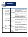
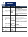
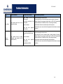
Technical Information Date of last update: Oct-11 Ref: D7.8.4/1011/E Application Engineering Europe CORESENSE™ DIAGNOSTICS FOR STREAM REFRIGERATION COMPRESSORS CoreSense™ Diagnostics for Stream Refrigeration Compressors ............................................................................... 1 1 Introduction .......................................................................................................................................................... 3 2 Specifications ........................................................................................................................................................ 3 3 Emerson CoreSense™ Diagnostics – Features ..................................................................................................... 3 4 3.1 “Jog” feature ................................................................................................................................................. 4 3.2 Crankcase heater (CCH) control.................................................................................................................... 4 3.3 Insufficient oil pressure protection .............................................................................................................. 5 3.4 Motor overheat protection .......................................................................................................................... 5 3.5 High discharge temperature protection ....................................................................................................... 5 3.6 Locked rotor protection................................................................................................................................ 5 3.7 Missing phase protection ............................................................................................................................. 5 3.8 Low voltage protection ................................................................................................................................. 5 3.9 Voltage imbalance protection ...................................................................................................................... 6 3.10 Flash memory information ........................................................................................................................... 6 3.10.1 The following asset information will be saved in the flash memory (EEPROM); ................................. 6 3.10.2 Compressor running status information will be saved in the flash memory (EEPROM): ..................... 6 3.10.3 Compressor Operating Parameters ...................................................................................................... 6 3.11 Modbus® communication ............................................................................................................................. 6 3.12 Local and remote reset ................................................................................................................................. 6 3.13 Alarm history and running conditions .......................................................................................................... 7 3.14 Compressor status codes.............................................................................................................................. 7 3.15 LEDs on the module to display the failure alarms ........................................................................................ 7 Electrical connections ........................................................................................................................................... 9 4.1 System wiring diagram ................................................................................................................................. 9 4.2 Terminal box and current sensing transformer connections .....................................................................10 4.2.1 Installation of current sensing module ...............................................................................................10 4.2.2 CoreSense™ Diagnostics with Υ/Δ motors ........................................................................................11 1/17 Technical Information 4.2.3 D7.21.2/1011/E CoreSense™ Diagnostics with part winding ......................................................................................11 5 CoreSense™ Diagnostics jumper settings..........................................................................................................13 6 CoreSense™ Diagnostics DIP-Switch setting .....................................................................................................13 7 Troubleshooting..................................................................................................................................................15 2/17 D7.21.2/1011/E Technical Information 1 Introduction CoreSense™ is an ingredient brand name for compressor electronics associated with Emerson‟s Copeland® brand products. CoreSense™ technology uses compressor as a sensor to unlock information from within the compressor providing value added features such as advanced motor protection, diagnostics, communication. With active protection, advanced algorithms, and features like fault history and LED indicators, CoreSense™ Diagnostics for Copeland compressors enable technicians to diagnose the past and recent state of the system, allowing for quicker, more accurate diagnostics and less down time. The CoreSense™ Diagnostics is initially available as standard with the 4- and 6-cylinder Stream compressors. Figure 1: Stream compressor with CoreSense™ Diagnostic 2 Specifications Power supply for control module (in front of the compressor) is 120VAC or 240VAC. Operating temperature Voltage requirements Inrush current for relay Voltage sensor module -32°C to 66°C 120 VAC or 240 VAC 19A 24 VAC Steady load current for relay Power rating for the module Storage temperature Protection class 3A 3VA -40°C to 85°C IP54 Table 1 3 Emerson CoreSense™ Diagnostics – Features Nr Feature Nr Feature 1 Motor Overheat Protection 8 Alarm History and Compressor Operating Conditions 2 Oil Pressure Protection 9 Crankcase Heater Control 3 Discharge Temperature Protection 10 Local and Remote Reset Capability 4 Locked Rotor Protection 11 Modbus Communication 5 Single Phase/Missing Phase Protection 12 Power Consumption Monitoring (Voltage, Current, Power Factor) 6 Voltage Imbalance Protection 13 Crankcase Heater Control 7 Low Voltage Protection 14 Compressor Run Status (Proofing) ® Table 2 3/17 Technical Information D7.21.2/1011/E Figure 2 3.1 “Jog” feature The reset button below the control module may be used as an emergency shutdown, such as for clearing liquid during a start-up. After the module re-boots (approximately 3 seconds) the compressor will run again. The reset button may be pushed as necessary to stop the compressor. Reset button Figure 3 3.2 Crankcase heater (CCH) control The sensor module contains an on-board CCH control relay. An auxiliary contactor is no longer required to turn the heater on when the compressor turns off. The appropriate voltage supply to the CCH power input terminals (115V/230V) is required. 4/17 Technical Information 3.3 D7.21.2/1011/E Insufficient oil pressure protection The CoreSense™ Diagnostics module replaces the mechanical oil pressure switch. Furthermore, it provides the added value of communication for insufficient oil pressure warning and lockouts via LED flash codes and/or a supervisory pack controller. Total insufficient oil pressure time for the compressor is stored and accumulated in the module memory. CoreSense™ Diagnostics will issue a warning when oil pressure differential falls below 0.48-0.62 bar for 4 seconds. Once the oil pressure differential falls below 0.48-0.62 bar for 2 minutes (120 sec), the module will shut the compressor off and a “low oil pressure lockout“ will be reported. Before using the reset button, troubleshooting needs to be done to understand the failure. The compressor will switch back on once the reset has been activated either manually or remotely through the communication network, or when power has been cycled to the CoreSense™ module. This feature is not applicable to Copeland compressor models 4MTL (Stream CO2 compressors) as these have no positive oil pump fitted and are “splash” lubricated. 3.4 Motor overheat protection Using Positive Temperature Coefficient (PTC) sensors on 4M* and 6M* Stream compressor models, the CoreSense™ Diagnostics module provides motor overheating protection. The CoreSense™ Diagnostic module replaces the Kriwan module INT69TM. Alarm condition: Trip condition: PTC Resistance > 4.5 kΩ; Reset condition: PTC Resistance < 2.5 kΩ; 5 min time delay. 3.5 High discharge temperature protection Discharge temperature protection is provided using a NTC sensor in the compressor cylinder head. The sensor is pre-installed at the factory and connected to the module. CoreSense™ will protect the compressor from high discharge temperature conditions. If the temperature sensor detects a discharge temperature higher than 154°C, the CoreSense™ will shut off the compressor until the temperature cools down to an acceptable level (about 130°C). Either trip or lockout alarm can be selected by user. Default is trip alarm. Trip/lockout value ≥ 154°C for 2 sec. Trip alarm: Automatic reset after 2 minutes; discharge temp < 130ºC. Lockout alarm: Manual reset is necessary. 3.6 Locked rotor protection Appears when the rotor is mechanically seized. Locked rotor current is expected to decrease within 4 seconds after the motor comes up to speed. 3.7 Missing phase protection If any one of the 3 power phases is missing immediately after the compressor contactor is energized, a singlephasing condition exists. The maximum response time shall be 1.2 seconds from the time of contactor energization. Alarm condition: If any phase voltage < 84% of max of 3 input voltages for a period of 1 second. Trip time: 5 minutes with automatic reset. Lockout condition: Appears after the 10 consecutive trip alarms. Manual reset (using reset button below the module or using remote reset by pack controller). In the case of a part winding motor this feature is detectable for primary winding only. Missing phase, voltage imbalance and low voltage are not detectable for the secondary winding. A missing phase can be detected during start-up, but not while the motor is running. 3.8 Low voltage protection Appears when there is a low supply voltage. 5/17 D7.21.2/1011/E Technical Information Alarm condition: Motor compressor voltage < low voltage setting at compressor running state. The default low voltage setting is 75% of the nominal line voltage stored in the module for 2 sec. Trip Time: 5 minutes. The module determines the operating frequency of the compressor. The compressor low voltage setting shall be lowered by the same percentage as the operating frequency if less than the nominal frequency. For example if a 60 Hz nominal frequency compressor is running at 57 Hz (5% less), then the low voltage setting shall be reduced by 5%. 3.9 Voltage imbalance protection The purpose of this protection feature is to protect the compressor against a voltage imbalance condition that leads to motor overheating. A configurable setting (default = 5%) for voltage imbalance is used to determine the operating limit of the compressor. Alarm condition: Trip: When the voltage imbalance > 5% (configurable). Reset: Automatic reset after 5 min; voltage imbalance < 5%. 3.10 Flash memory information Emerson Climate Technologies can provide a software to access EEPROM information. 3.10.1 The following asset information will be saved in the flash memory (EEPROM); Compressor model number Compressor serial number Compressor model number modified Compressor serial number modified Sensor module firmware revision 3.10.2 Compressor running status information will be saved in the flash memory (EEPROM): Number of compressor running hours Number of compressor starts Number of resets and type of reset Accumulated runtime without good oil pressure Number of relay cycles 3.10.3 Compressor Operating Parameters Current Voltage Power factor Power consumption Discharge temperature values 3.11 Modbus® communication ® CoreSense™ Diagnostics has communication capability via a Modbus network connection. With communication enabled, CoreSense™ warnings, trips and lockouts can be displayed and recorded in a pack controller such as the iPro Rack Controller from Dixell. ® The CoreSense™ Diagnostics module is compatible with any other pack controller that has Modbus protocol. 3.12 Local and remote reset The CoreSense™ Diagnostics module is equipped with a reset button placed below the control module. The reset button may be pushed as necessary to stop the compressor. The CoreSense™ Diagnostics module is equipped with a remote reset capability, such that if a compressor is off in a lockout condition, the user can remotely restart the compressor through their rack controller or compatible remote access software. NOTE: Service contractor and end user policies need to be considered when deciding whether or not to use the remote reset feature in the pack controller. 6/17 D7.21.2/1011/E Technical Information 3.13 Alarm history and running conditions Operating information Alarm history Number of compressor running hours - 8 days alarm history Accumulated running time without good oil pressure Most recent 10 alarms Number of switching cycles Total number of alarms since the compressor first operation Compressor power consumption* Current, voltage, power factor* *This data is not stored in CoreSense™ EEPROM memory. These values can be stored in a laptop using CoreSense™ PC ® Interface Software or Modbus communication. Table 3 3.14 Compressor status codes Steady green: An indication of normal operation. There are no faults or issues with the compressor. Flashing green: An indication that there is an alert (warning) condition. The compressor can still be running. Flashing orange: An indication that the compressor has tripped with auto reset. Flashing red: An indication that the compressor is in lockout state. Solid red: An indication that the control module has failed. 3.15 LEDs on the module to display the failure alarms For warning/alert (green), trip and lockout (red), the flash count is defined as 0.1 second „on‟ and 0.4 second „off‟ with a 2-second pause before the flash count repeats (timings are +/- 50 ms). Definitions: Trip: The module has shut off the compressor due to a fault condition. The compressor will be available to run when the fault condition no longer exists, and the minimum off time has been satisfied. Lockout: The module has shut off the compressor due to a fault condition. The compressor will be available to run again when the fault condition has been cleared and manual or remote reset is done. Alert alarms Compressor will not turn off. Trip alarms Compressor turns off for some time with automatic reset. Lockout alarms Compressor turns off. Manual reset necessary. Figure 4 7/17 Technical Information LED flashes count Status LED description 1 Low Oil Pressure 2 Auto reset time NA Low Oil Pressure N/A NA Motor Protection Trip NA 2 min 3 Discharge Temp. Discharge Temp. 4 Current Sensor Fault NA NA NA 5 Communica tion Error NA NA NA 6 NA Locked Rotor Locked Rotor 5 min 7 NA Missing Phase Missing Phase 5 min 8 N/A Low Voltage Low Voltage 5 min 9 N/A Voltage Imbalance Discharge 2 min Temp. Voltage 5 min Imbalance Lockout condition D7.21.2/1011/E Status LED troubleshooting information If flashing green, compressor has been without sufficient oil pressure for 4 seconds. If flashing red, compressor has been without sufficient oil pressure for 2 minutes. If flashing orange, compressor is turned off because motor temperature has NA exceeded set point. (3 series PTCs; 1 input) (Trips at 4.5K Ohms, and will reset when below 2.75K Ohms.) If flashing green, the discharge temperature probe is open or disconnected. If flashing orange, discharge temperature has exceeded set point; compressor is Exceeds max turned off for 2 minutes before resetting. set point If flashing red, discharge temperature has (configured in exceeded set point and the compressor is EEPROM from locked out. iPRO) (The customer has configured the module to lock out when the DLT temperature exceeds the maximum set point.) DLT probe is FACTORY INSTALLED If flashing green, current sensor is NA disconnected from the module. Compressor run state is not known by module. Communication between Control module and iPro (/System) Controller has been lost. Communication between Control module NA and Sensor module has been lost. Configuration miss-match between SW configuration from iPro and HW (network mode) If flashing orange, compressor failed to start, and excessive current may be present in the compressor. The compressor is 10 consecutive turned off and will remain off for 5 minutes. If flashing red, compressor failed to start, events and excessive current may be present in the compressor. The compressor is locked out after 10 consecutive events. If flashing orange, compressor is turned 10 consecutive off due to missing phase. events If flashing red, the compressor is locked out after 10 consecutive missing phase alarms. If flashing orange, compressor is turned 10 consecutive off due to low compressor voltage. If flashing red, the compressor is locked events out after 10 consecutive low voltage alarms. If flashing orange, compressor is turned 10 consecutive off due to voltage imbalance. If flashing red, the compressor is locked events out after 10 consecutive voltage imbalance. Without sufficient oil pressure for 2 minutes Table 4 8/17 Technical Information 4 Electrical connections 4.1 System wiring diagram D7.21.2/1011/E Fuses and wire cable sizing must be done in accordance with all applicable electrical code standards. Figure 5 below shows the recommended basic system wiring for a compressor with CoreSense™. Figure 5: Wiring diagram Figure 6: CoreSense™ wiring terminals description 9/17 Technical Information D7.21.2/1011/E Figure 7: CoreSense™ module with current sensor 4.2 Terminal box and current sensing transformer connections For space reasons inside the compressor terminal box wires L1 and L2 connected to the sensor module need to be exchanged in such a way that the black wire is connected to terminal 2 (V) and the white wire goes to terminal 1 (U) on the terminal plate as shown on the drawing. This results in that the current of L2 is sensed instead of L1. 4.2.1 Installation of current sensing module One of the motor power leads passes through the “toroid” (current sensing module). Information from the current sensing module is used to determine running amps, power consumption and locked rotor conditions. There are 3 voltage sensing leads attached to the motor terminals and connected to the sensor module. Two of the leads are white, and one is black. For proper calculation of power factor and motor power it is necessary for the black voltage sensing lead and the power lead through the current sensing module to be connected to the same motor terminal. Class II transformers have a maximum VA (Volt-Ampere) rating of less than 100 and a maximum secondary output of 30 VAC. Figure 8: Current sensing module and T-Box wiring 10/17 Technical Information 4.2.2 D7.21.2/1011/E CoreSense™ Diagnostics with Υ/Δ motors Terminal box and the current sensing “toroid” connections are factory-installed. One of the motor power leads must be routed through Current Sensing Transformer (see Figures 9 & 10 below). Figure 9: Current sensing transformer Figure 10: Wiring sensor module and leads routed through the current sensor One motor lead must be routed through the centre opening of the current sensing transformer. 4.2.3 CoreSense™ Diagnostics with part winding If using the CoreSense™ Diagnostics module with a part-winding start motor, one power lead of each of the windings should be passed through the current sensing transformer in the same direction (see Figures 10 and 11) to provide accurate compressor proofing. If the leads (L2 and L8 in picture below) are not routed in the same direction, the running current may indicate close to zero. 11/17 Technical Information D7.21.2/1011/E Figure 11: Wiring part winding Figure 12: Wiring Sensor module and leads routed through the current sensor 12/17 Technical Information 5 D7.21.2/1011/E CoreSense™ Diagnostics jumper settings The last compressor in the daisy-chain must be “terminated” by moving the jumper from JP5 to JP3. For all other compressors the jumper should remain in the default JP5 position. JP4 should be set “1-2” if connected to an iPro rack controller. Set JP4 to “2-3” for other pack controllers. Do not remove JP1. This is reserved for future use. Figure 13 6 CoreSense™ Diagnostics DIP-Switch setting Figure 14: CoreSense™ Diagnostics DIP-Switch setting 13/17 Technical Information D7.21.2/1011/E Assign a unique node address to each CoreSense™ diagnostics module using switches 1 through 5. a. Set the communications baud rate for the module using switch 7. “Off” = 19200 baud, “On” = 9600 baud. The baud rate for each module should be set to match the rack controller. b. Set switch 8 to “Off” for no parity, to “On” for even parity. c. Set switch 9 to “Off” for stand-alone mode, to “On” for network mode. Network mode will generate a communications error if the rack controller fails to communicate with the device. For stand-alone mode, no communications are expected so the communication error is blocked. d. Factory default setting is “On” for dip-switch 10, ie, discharge temperature protection. If you want to disconnect the discharge temperature sensor, turn off dip-switch 10. Push the reset button after changing the switch settings. Ensure that the dip-switch settings on each module match the settings for the selected controller communication port. Information in this document is subject to change without notification. 14/17 D7.21.2/1011/E Technical Information 7 Troubleshooting Flash code Alarm conditions Possible failure reasons Warning: Appears when the differential oil pressure is less than 0.48 – 0.62 bar for 4 seconds. 1 Insufficient pressure oil Lockout: Appears when the differential oil pressure is less than 0.48 – 0.62 bar for 2 minutes continuous, or intermittent but determined to be unsafe. Trip: Appears when the PTC Thermistor resistance is > 4.5 kΩ. 2 Motor overheat Lockout: Appears when consecutive motor overheat alarms occur. 10 trip Loose wiring connections between CoreSense™ module and oil sensor. Faulty oil sensor (missing O-ring or clogged sensor screen). Faulty oil pump. Clogged strainer screen or worn bearings. Motor rotor seized. is mechanically Open circuit in harness. Connector pin not engaging at connector on control module Faulty CoreSense™ module. Troubleshooting measures Verify the oil level present in the sight glass. If the oil is not present, resolve reservoir oil supply problem or oil level control setting issues. Verify that the harness is fully engaged to the sensor. Measure oil pump differential pressure. If less than 7 to 9 psi, inspect for clogged oil screen, faulty oil pump, liquid floodback or worn bearings. If good oil pressure exists, measure resistance across the oil sensor while the compressor runs. If the sensor resistance is "open" inspect for clogged sensor screen or missing O-ring. If sensor resistance is "closed", temporarily jumper across the harness connector pins (do not damage the pins!) while the compressor runs. If the oil warning does not go away, verify harness connector engagement at the module circuit board. In case of trip alarm, allow the motor to cool down for a minimum of 2 minutes (it may take longer) and the compressor will start automatically. In case of lockout alarm or multiple trips, check PTC resistance when the motor is cold (off for at least an hour). If resistance is high, inspect for faulty sensor or loose connection under terminal plate. If resistance is low, inspect for loose terminal strip connections, harness connection failure at circuit board, open harness circuit or high motor temp due to return gas temperature, motor voltage or load condition. Open discharge probe (faulty). 3 Discharge temp protection Warning: When the discharge temperature sensor is defective or disconnected. Trip/Lockout: When the discharge temperature is > 154°C for 2 seconds. The probe connection has not been made to the harness connector. The connector is not plugged into the CoreSense™ circuit board. The Discharge temperature has exceeded the maximum limit 154°C. Blocked condenser. If there is a warning, verify proper probe connection to the harness and proper harness connection into the circuit board. If there is a warning, unplug the discharge temp probe and verify if the resistance of the probe is as specified vs its approximate ambient temperature. If the probe resistance is correct inspect the harness connector receptacle for damage and apply NyoGel 760G connector lubricant. Trip or Lockout: resolve system issues (high superheat, high head pressure), inspect for mechanical damage that can lead to high temps (valve plate gasket, suction or discharge valve failure). Possible loss of refrigerant. 15/17 D7.21.2/1011/E Technical Information Flash code 4 Connection lost CT to sensor 5 Communication Error 6 Locked rotor 7 Missing phase Alarm conditions Possible failure reasons Warning: Appears when the signal from current sensor is not communicated to the sensor module. The current sensor is not connected to the sensor module. Faulty current sensor. Faulty sensor module. Warning: Appears when there is no communication between control module and sensor module or rack controller Communication between CoreSense™ control module and rack controller has been lost. Communication between the CoreSense™ control module and the sensor module has been lost. Trip: Appears when the excessive current is present in the compressor. Refer AE bulletin for more details. Motor rotor is mechanically seized. Excessive current present in the compressor. Lockout: Appears when 10 consecutive locked rotor trip alarms occur. Damaged valve plates in cylinder head. Trip: Appears when there is a missing phase / single phasing. Loose wiring connections at the terminals inside compressor T-Box. Lockout: Appears consecutive missing alarms occur. Worn out contactors. when phase 10 trip Line break in one of the phases. Troubleshooting measures Verify if the CT connector is connected to the sensor module. If not connect the 4-pin current sensor connector into the sensor module. Verify if there is continuity between pin 3 & 4 (closest to the latch) of the current sensing connector. The resistance should be less than 1 Ω. If the resistance is greater than 1 Ω, replace the current sensing module. Be certain that the receptacles are fully engaged in the connector block. Verify if the Amp and Volts values are correctly displayed. If not, inspect the wire harness connector to ensure that the pins are fully engaged. If the above-mentioned trouble shooting measures didn't give the positive results, the reason is faulty sensor module or mis-installed connector. Replace the faulty sensor module with new one. Is there a communication network? If not, set the network dip-switch to "stand-alone" and press reset. Is there a communication network? If not, verify that the communication harness is engaged at both the CoreSense™ module and the sensor module. If the LED on the top edge of the sensor module is dark, verify 24VAC power to the sensor module, or replace the sensor module. If communication network amber light is continuously on, reverse the communication wire polarity. If voltage between centre pin and the right or left pin isn't 2.3-2.6VDC, inspect for communication wire failure or wire strands that are "shorting" between the wires or to ground. Verify that motor voltage is adequate (+/- 10% of nominal rated voltage), especially during the starting event. Start compressor with no load. If it does start with no load, inspect the valve plate(s) for damage or look for other causes of leak-back. Verify voltage supply from the main power buss. Verify voltage into and out of contactor (Repair or replace contactor if necessary). Verify that motor electrical connections are tight at the compressor motor terminals. 16/17 D7.21.2/1011/E Technical Information Flash code Alarm conditions Possible failure reasons Supply voltage specified range. 8 Low voltage Trip: Appears when there is a low compressor voltage. is not in Troubleshooting measures the Loose wiring connections at the terminal plate. Worn out contactors. Faults with other electrical loads. peripheral Loose wiring connections at the compressor terminal plate inside TBox. 9 Voltage imbalance Trip: Appears when the voltage imbalance value exceeds the set value (default 5%). Worn out contactors. Faults with other electrical loads. peripheral Single phasing conditions. Verify voltage supply from the main buss. Verify voltage into and out of contactor (repair or replace contactor if necessary). Measure voltage at the compressor terminal (refer to AE10-1244, Recommended Contactor Selection for 3-Phase Motor Control – Power Supply Problems). Verify that motor electrical connections are tight at the compressor. Verify that there are not any faults with other peripheral electrical loads (for example fan motors). Verify voltage supply from the main buss. Verify voltage into and out of contactor (repair or replace contactor if necessary). Measure voltage at the compressor terminal (refer to AE10-1244, Recommended Contactor Selection for 3-Phase Motor Control– Power Supply Problems). Verify that motor electrical connections are tight at the compressor. Verify that there are not any faults with other peripheral electrical loads (for example fan motors). 17/17