1
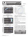
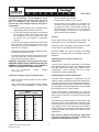
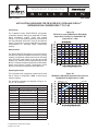
Application
Engineering
Application
Engineering
B
L LL E L T EI
BU U
AE4-1318 R1
N
T
I
N
AE-1318 R1
June 2008
APPLICATION GUIDELINES FOR ZB*KC/ZB*KCE COPELAND SCROLL®
REFRIGERATION COMPRESSORS 7 TO 15 HP
Introduction
Figure 1A
ZB*KCE (excluding ZB95KCE & ZB114KCE)
Application Envelope for R404A/R507 MT
Applications 7-15Hp
The Copeland Scroll® ZB*KC/ZB*KCE refrigeration
compressor product offering has expanded to include
higher horsepower models. These new models
include 7-15 Hp and produce between 50,000 Btu/H
and 114,000 Btu/H at 20/120°F using 60 Hz electrical
power. This bulletin covers the application parameters
recommended for operating these compressors
properly.
Nomenclature
The ZB*KC/ZB*KCE refrigeration scroll model number
includes two digits that indicate the amount of cooling
capacity in thousands of Btu/H at the 60 Hz ARI rating
point (20/120°F) with R404A in the third and fourth
location. (e.g. ZB92KC produces approximately 92,000
Btu/H). For actual compressor performance information
please visit Emerson Climate Technologies Online
Product Information at www.emersonclimate.com
Operating Envelope
Figure 1B
ZB95KCE & ZB114KCE Application Envelope for
R404A/R507 MT Applications 7-15Hp
The Copeland Scroll refrigeration models can be used
with a variety of refrigerants. Table 1 shows these
selection options.
The operating envelopes are depicted in Figures 1A,
1B, 1C, 1D, 1E and 1F.
20 F SH
TABLE 1
Model
Refrigerant
Lubricant
ZB50KC/E
R22/407/R404A/507/134a
MO/POE
ZB58KC/E
R22/407/R404A/507/134a
MO/POE
ZB66KC/E
R22/407/R404A/507/134a
MO/POE
ZB76KC/E
R22/407/R404A/507/134a
MO/POE
ZB88KC/E
R22
MO/POE
ZB95KC/E
R22/R404A/507/134a
MO/POE
ZB114KC/E
R22/R404A/507/134a
MO/POE
ZB56KC/E
R22/R404A/507/134a
MO/POE
ZB68KC/E
R22/R404A/507/134a
MO/POE
ZB75KC/E
R22/R404A/507/134a
MO/POE
ZB92KC/E
R22/R404A/507/134a
MO/POE
ZB11MC/E
R22/R404A/507/134a
MO/POE
© 2008 Emerson Climate Technologies
Printed in the U.S.A.
1
Application Engineering
B
U
L
L
Figure 1C
ZB95KCE & ZB114KCE Application Envelope for
R404A/R507 HT Applications 7-15Hp
E
T
I
N
AE-1318 R1
Figure 1F
ZB*KCE Application Envelope for R134A HT
Applications 7-15Hp
20 F SH
260° F DLT Limit, 20° F Superheat
Evaporating Temperature
Figure 1D
ZB*KC (excluding ZB95KC & ZB114KC)
Application Envelope for R22 HT Applications
7-15Hp
,
Voltage / Frequency Restrictions
Due to inadequate cooling from refrigerant flow through
the compressor, the following 50 Hz applications are
not approved:
20 F Min. SH
ZB95KC / ZB95KCE / ZB114KC / ZB114KCE-TWD
420 V 50 Hz
ZB95KC / ZB95KCE / ZB114KC / ZB114KCE-TW5
200-220 V 50 Hz
Compressor Lubrication
The compressors can be used with different lubricants
depending upon the refrigerant used. See Form 93-11
for a complete list of all Emerson approved lubricants.
Figure 1E
ZB95KC & ZB114KC Application Envelope for R22
HT Applications 7-15Hp
20 F SH
Accumulators
Due to the inherent ability of scroll compressors to
handle liquid refrigerant in flooded start and defrost
cycle operation conditions, accumulators may not
be required. An accumulator is required on single
compressor systems when the charge limitations
exceed those values listed in Table 2. On systems
with defrost schemes or transient operations that
allow prolonged uncontrolled liquid return to the
compressor, an accumulator is required unless a
TABLE 2
CHARGE LIMITS
Model Family
© 2008 Emerson Climate Technologies
Printed in the U.S.A.
2
Charge Limits
ZB50, 58, 66, 76, 88, 95, 114 KC/E
16 lbs
ZB56,68,75,92KC/E & ZB11MC/E
17 lbs
Application Engineering
B
U
L
L
E
suction header of sufficient volume to prevent liquid
migration to the compressors is used. Excessive liquid
floodback or repeated flooded starts will dilute the oil
in the compressor causing inadequate lubrication and
bearing wear. Proper system design will minimize liquid
floodback, thereby ensuring maximum compressor life.
T
I
N
Crankcase Heater
Crankcase heaters are required on systems when the
system charge exceeds the recommended charge
limit. See Table 2.
The listed crankcase heaters (Table 3) are intended
for use only when there is limited access. The heaters
are not equipped for use with electrical conduit. Where
applicable, electric safety codes require heater lead
protection, a crankcase heater terminal box should
be used. Recommended crankcase heater terminal
cover and box numbers are listed in Table 3A. If
there are any questions concerning the application,
contact the Emerson Climate Technologies Application
Engineering department.
If an accumulator must be used, an oil return orifice
size in the range of 0.040 - 0.075 inches (1 - 1.9 mm)
is recommended. A large-area protective screen no
finer than 30 x 30 mesh (0.6 mm openings) is required
to protect this small orifice from plugging with system
debris. Tests have shown that a small screen with
a fine mesh can easily become plugged causing oil
starvation to the compressor bearings.
Screens
Advanced Scroll Temperature Protection (ASTP)
The use of screens finer than 30 x 30 mesh (0.6 mm
openings) anywhere in the system is not recommended.
Field experience has shown that finer mesh screens
used to protect thermal expansion valves, capillary
tubes, or accumulators can become temporarily or
permanently plugged with normal system debris
and block the flow of either oil or refrigerant to the
compressor. Such blockage can result in compressor
failure.
After extensive research and trials Emerson Climate
Technologies found a way to install a Therm-ODisc® temperature sensitive snap disc in the ZB50,
ZB58, ZB66, ZB76, ZB95, ZB88 and ZB114 scroll
compressors. This acts to protect the compressor from
TABLE 3
CRANKCASE HEATERS
Model
Part No.
Volts Watts
ZB50, ZB58,
ZB66, ZB76
ZB88, ZB95
ZB114
Select by voltage
018-0067-00
018-0067-01
018-0067-02
018-0067-03
120
240
480
575
90
90
90
90
Leads
48"
48"
48"
48"
Select by voltage and lead length
ZB56
ZB68
ZB75
ZB92
ZB11M
018-0077-00
018-0077-01
018-0077-02
018-0077-03
018-0077-04
018-0077-05
018-0077-06
240
120
480
575
240
480
575
70
70
70
70
70
70
70
26"
26"
26"
26"
34"
34"
34"
TABLE 3A
CONDUIT READY HEATER BOX KITS
Model Number
Kit Number
ZB50, ZB58, ZB66
ZB76, ZB88, ZB95, ZB114
998-7029-00
ZB56, ZB68, ZB75
ZB92, ZB11M
998-7015-00
© 2008 Emerson Climate Technologies
Printed in the U.S.A.
AE-1318 R1
Figure 2
3
Application Engineering
B
U
L
L
E
discharge gas overheating. Events such as loss of
charge, evaporator blower failure, or low side charging
with inadequate pressure will cause the discharge gas
to quickly rise above a critical temperature. Once this
critical temperature is reached, the ASTP feature will
cause the scrolls to separate and stop pumping but
allow the motor to continue to run. After the compressor
runs for some time without pumping gas, the motor
protector will open. Depending on the heat build up
in the compressor, it may take up to two hours for the
ASTP to reset. The addition of the Advanced Scroll
Temperature Protection makes it possible to eliminate
the discharge line thermostat previously required. A
graphic explanation and a short video clip are available
on the web site, www.emersonclimatecontractor.com/
ASTP. Compressors with this feature will have the
Advanced Scroll Temperature Protection label (Figure
2) located directly above the terminal box.
Discharge Line Thermostat
The addition of the Advanced Scroll Temperature
Protection on the ZB50, ZB58, ZB66, ZB76, ZB88,
ZB95 and ZB114, as well as the internal discharge
temperature protection described in the section
titled “Motor Protection” for the ZB56, ZB68, ZB75,
ZB92, and ZB11M, makes it possible to eliminate the
discharge line thermostat in most applications.
T
I
N
Pressure Controls
Both high and low pressure controls are required
and the following are the minimum and maximum set
points. Refer to Table 4 for proper settings.
IPR Valve
The 7 through 15 horsepower refrigeration scroll
compressors DO NOT have an internal high pressure
relief valve. To provide safe operation, a high pressure
control set no higher than 445 psig must be used in all
applications (reference Table 4).
Motor Protection
The larger horsepower refrigeration scroll compressors
have either line break protection or the use of sensors
with an electronic module. The type of protection is
obtained from the protector code in the model number.
Table 5 lists the various models protector number and
the type of protection.
For the INT69SCY, there are five PTC (positive
temperature coefficient) internal thermisters connected
in series that react with avalanche resistance in the
event of high temperatures. Four of the thermisters are
TABLE 4
PRESSURE CONTROL SETTINGS
Model
Control
Type
R404A/R507
R134a
R22
ZB50, ZB58,
ZB66, ZB76,
ZB95, ZB114
Low
High
17 psig min.
454 psig max.
4 psig min.
263 psig max
37 psig min.
381 psig max
ZB88
Low
High
N/A
N/A
N/A
N/A
37 psig min.
381 psig max
ZB56, ZB75, ZB68,
ZB92, ZB11M
Low
High
17 psig min.
454 psig max.
4 psig min.
263 psig max
37 psig min.
381 psig max
TABLE 5
MOTOR PROTECTION
Models with Line Break Protection
ZB50, ZB58, ZB66, ZB76, ZB88, ZB95, ZB114
(note: electric code = TF*)
No module
Models with Electronic Module
ZB56, ZB68, ZB75, ZB92, ZB11M
(note: electric code = TW*)
p/n: 071-0620-00
Model: INT69SCY
Models with Electronic Module
ZB95, ZB114
(note: electric code = TW*)
p/n: 071-0641-00
Model: INT69SU
© 2008 Emerson Climate Technologies
Printed in the U.S.A.
4
AE-1318 R1
Application Engineering
B
U
L
L
E
T
I
N
AE-1318 R1
Figure 3
Scroll Wiring Schematic
used to sense motor temperatures and the fifth is used
as a discharge temperature sensor. For the INT69SU,
there are four PTC (positive temperature coefficient)
internal thermisters connected in series. All four are
used to sense motor temperature. The thermister
circuit is connected to the protector module terminals
S1 and S2.
PLC operated control circuits may not always provide
this minimum current. In these cases modifications
to the PLC control circuit are required. Consult your
application engineering department for details.
Phase Protection
The INT69SCY module provides phase protection
for the compressor. The module senses the correct
phase sequence, phase loss and voltage sag for each
leg (L1, L2 and L3) of the incoming power supplied to
the compressor. At installation the three phases of the
power supply must be wired in the correct 120° phase
sequence. This will ensure the compressor will start
and operate in the correct clockwise direction.
When any thermister reaches a limiting value, the
module interrupts the control circuit and shuts off the
compressor. After the thermister has cooled sufficiently,
the resistance will decrease, thus allowing the module
to reset. However, the module has a 30-minute time
delay before reset after a thermister trip.
For all other compressors, conventional internal line
break motor protection is provided.
The INT69SCY module trips (M1-M2 contacts open)
when the module senses a phase loss. There is a 5
minute time delay before the module attempts a restart.
If all three phases are present, then the module will
reset (M1-M2 contacts will close) and the compressor
will start and run. If not, the module will attempt a
restart after another 5 minute time delay. After 10
failed attempts to restart, the module will lock-out (M1M2 contacts will remain open) and can only be reset
by removing the power from T1-T2 for a minimum of
5 seconds.
Programmable Logic Controller Requirements
If the INT69SCY (071-0620-00) or INT69SU (0710641-00) module is applied in conjunction with a
Programmable Logic Controller, it is important that a
minimum load is carried through the M1-M2 control
circuit contacts.
The minimum required current through the module
relay contacts needs to be greater than 100 milliamps
but not to exceed 5 amps. If this minimum current is
not maintained, this has a detrimental effect upon the
long-term contact resistance of the relay and may
result in false compressor trips.
© 2008 Emerson Climate Technologies
Printed in the U.S.A.
The INT69SCY is intended to protect the compressor.
The L1/L2/L3 and S1/S2 leads are pre-wired on the
compressor and are engineered to work in conjunction
with the motor protector module.
The module
5
Application Engineering
B
U
L
L
E
T
b. If the measurement is less than 1 volt and the
compressor is not running, then the problem
is external to the INT69SCY or INT69SU
module.
The following field troubleshooting procedure can be
used to evaluate the solid state control circuit: Refer to
Table 6 for a technical data summary.
c.
Module Voltage Supply Troubleshooting
•
Measure the voltage across T1-T2 to ensure
proper supply voltage.
•
Determine the control voltage by using a voltmeter
AE-1318 R1
a. If the measured voltage is equal to the control
volts then the M1-M2 contacts are open.
Module and Sensor Functional Check
Verify that all wire connectors are maintaining
a good mechanical connection. Replace any
connectors that are loose.
N
and then measure the voltage across the M1-M2
contacts:
leads should not be moved or extended because
of the possibility of inducing electronic noise into
the INT69SCY, which could cause false trips of the
module.
•
I
If the voltage is greater than 1 volt but less than
the control voltage, the module is faulty and
should be replaced.
Sensor Troubleshooting
•
Remove the leads from S1-S2, and then by using
an ohmmeter measure the resistance of the
incoming leads.
CAUTION: Use an Ohmmeter with a maximum
TABLE 6
Emerson P/N
071-0520-07
071-0520-05
071-0620-00
071-0641-00
Manufacturer P/N
T.I. 30AA201E
Kriwan 69SC-DV
Kriwan 69SCY
Kriwan 69SU
T1-T2 Module Power
Voltage Supply
120V & 240V
120V & 240V
120V & 240V
120V & 240V
Frequency
50Hz & 60Hz
50Hz & 60Hz
50Hz & 60Hz
50Hz & 60Hz
M1-M2 Module Output Contacts
Maximum Voltage
N/A
250VAC
250VAC
250VAC
Maximum Current
5 Amps
5 Amps
5 Amps
5 Amps
Minimum Current
100 milliamps
100 milliamps
100 milliamps
100 milliamps
Relay Output
2.5 A, 600 V
5 A, 300 VA
5 A, 300 VA
5 A, 300 VA
Power Output
< 5.5 VA
<3 VA
<3 VA
<3 VA
Trip Out Resistance
N/A
4500W ± 20%
4500W ± 20%
4500W ± 20%
Reset Resistance
N/A
2750W ± 20%
2750W ± 20%
2750W ± 20%
Reset Time
30 min ± 5 min
30 min ± 5 min
30 min ± 5 min
30 min ± 5 min
Manual Reset
T1-T2 interrupt for
minimum of 5 sec
T1-T2 interrupt for
minimum of 5 sec
T1-T2 interrupt for
minimum of 5 sec
T1-T2 interrupt for
minimum of 5 sec
Phase Sensor
Non Phase Sensing
Non Phase Sensing
3
Non Phase Sensing
Phase Monitoring
Circuit Rating
Non Phase Sensing
Non Phase Sensing
3 AC 50/60Hz
120V to 632V
Non Phase Sensing
Trip Delay
Non Phase Sensing
Non Phase Sensing
5 min delay before
restart attempt
Non Phase Sensing
Lockout
Non Phase Sensing
Non Phase Sensing
After 10 module trips
Non Phase Sensing
Reset For Lockout
Non Phase Sensing
Non Phase Sensing
T1-T2 interrupt for
minimum of 5 sec
Non Phase Sensing
S1-S2 Thermal Protection
L1-L2-L3 Phase Monitoring
© 2008 Emerson Climate Technologies
Printed in the U.S.A.
6
Application Engineering
B
U
L
L
E
of 9 VDC for checking – do not attempt to check
continuity through the sensors with any other
type of instrument. Any external voltage or
current may cause damage requiring compressor
replacement.
b. If the M1-M2 contacts are open, the measured
S1-S2 value is above 2750 ohms ±20% and
the compressor has been tripped less then
30 minutes then the module is functioning
properly.
Replace all wire leads and use a voltmeter to verify
the M1-M2 contacts are closed.
•
If the M1-M2 contacts remain open and S1-S2 are
less than 2500 ohms, remove leads from the M1M2 contacts and jumper together;
Go
to
Compressor
Troubleshooting.
Supply
AE-1318 R1
•
Ensure proper voltage on each phase.
•
Remove power to the module for a minimum of 5
seconds to reset and replace all wire leads. Reenergize the module. If the M1-M2 contacts are
open with proper voltage to T1-T2, L1/L2/L3 and
proper resistance to S1-S2 then the module is
faulty and should be replaced.
Polyol ester lubricant (POE) must be provided if the
refrigeration scroll is used with HFC refrigerants.
Copeland Scroll refrigeration compressors intended
for use with R22 are supplied with mineral oil.
Reference Table 7 for proper oil charge. See Form
93-11 for a complete list of all Emerson approved
lubricants.
Oil Management for Single Compressor
Applications
CAUTION: Compressor should start at this time.
HOWEVER DO NOT LEAVE JUMPER IN PLACE FOR
NORMAL SYSTEM OPERATIONS. THE JUMPER IS
USED FOR DIAGNOSTIC PURPOSES ONLY.
•
N
Oil Type
If the S1-S2 wire leads read less than 2750 ohms
±20% and the M1-M2 contacts are open, reset
the module by removing the power to T1-T2 for a
minimum of 5 seconds.
•
I
be at a potential up to 600VAC.
a. During normal operation, this resistance value
should read less than 4500 ohms ±20%.
•
T
If the oil level is above the sight glass, oil circulation
rates greater than 1.5% may be experienced with
the ZB50, ZB58, ZB66, ZB76, ZB88, ZB95 & ZB114
compressors. This is especially true in the larger
compressors in 60 Hz applications.
Voltage
Compressor Voltage Supply Troubleshooting
Oil Management for Rack Applications
•
Remove phase sensing leads from the module
from L1/L2/L3.
•
Use a voltmeter to measure the incoming 3 phase
voltage on L1/L2/L3. WARNING: L1/L2/L3 could
Copeland Scroll refrigeration compressors may be
used on multiple compressor parallel rack applications.
This requires the use of an oil management system to
maintain proper oil level in each compressor crankcase.
The sight glass connection supplied can accommodate
the mounting of the oil control devices.
TABLE 7
COMPRESSOR OIL CHARGE
Model
Initial
Recharge
ZB50
ZB58
ZB66
ZB76
ZB88
ZB95
ZB114
ZB56
ZB68
ZB75
ZB92
ZB11M
85
85
110
110
110
110
110
140
140
140
140
140
81
81
106
106
106
106
106
137
137
137
137
137
© 2008 Emerson Climate Technologies
Printed in the U.S.A.
Unlike Semi-Hermetic compressors, the scrolls do
not have an oil pump with accompanying oil pressure
safety controls. Therefore, an external oil level control
is required.
The OMB Oil Level Management Control combines the
functions of level control and timed compressor shutoff should the level not come back to normal within
a set period of time. This device has been found to
provide excellent performance in field tests on Scroll
compressors and is recommended for parallel system
applications.
Note: Emerson Climate Technologies' Application
Engineering Department should be contacted for
approved oil management systems.
7
Application Engineering
B
U
L
L
E
T
I
N
AE-1318 R1
Immediately after system start-up the oil reservoir level
will fluctuate until equilibrium is reached. It is advisable
to monitor the oil level during this time to assure
sufficient oil is available. This will prevent unnecessary
trips of the oil control system.
Note: The use of standard soft grommets is not
recommended for our refrigeration scroll rack
installations. These “softer” mounts allow for
excessive movement that will result in tube breakage
unless the entire system is properly designed.
Note: If oil management problems are occurring
please refer to AE 17-1320 or contact the Emerson
Climate Technologies Application Engineering
Department.
Connection Fittings
Note: ZB50, 58, 66, 76, 88, 95, 114 are not
approved for rack applications due to compressor
limitations.
Compressor Mounting
Compressor mounting must be selected based on
application. Consideration must be given to sound
reduction tubing reliability. Some tubing geometry or
“shock loops” may be required to reduce vibration
transferred from the compressor to external tubing.
Mounting for Rack Systems
Specially designed steel spacers and rubber isolator
pads are available for our refrigeration scroll 7.5-15 HP
scroll rack applications. This mounting arrangement
limits the compressors motion thereby minimizing
potential problems of excessive tubing stress. Sufficient
isolation is provided to prevent vibration from being
transmitted to the mounting structure. This mounting
arrangement is recommended for multiple compressor
rack installations. See Figure 4 for a detail for this
mounting system.
Figure 4
7.5 - 15 HP Rack Mounting
027-0115-00
RUBBER PAD
© 2008 Emerson Climate Technologies
Printed in the U.S.A.
Three Phase Scroll Compressors – Directional
Dependents
Scroll compressors are directional dependent; i.e. they
will compress in one rotational direction only. Three
phase Scrolls will rotate in either direction depending
on power phasing. Since there is a 50/50 chance
of connected power being “backwards”, contractors
should be warned of this. Appropriate instructions or
notices should be provided by the OEM. To eliminate
the possibility of reverse rotation a Copeland Phase
Control line monitor, P/N 085-0160-00, or other phase
monitor is recommended.
Verification of proper rotation can be made by observing
that the suction pressure drops and the discharge
pressure rises when the compressor is energized.
Additionally, if operated in reverse the compressor is
noisier and its current draw is substantially reduced
compared to tabulated values.
TABLE 8
Model
102-0119-00
WASHER
027-0280-00
STEEL SPACER
There are various connection fittings available for
Copeland Scroll refrigeration compressors. The
various options are shown in Table 8.
KIT #527-0158-00
8
Rotalock Spud
Connection
Stub
Connection
Suction
Discharge
Suction
Discharge
ZB50
1-3/4 - 12
1-1/4 - 12
1-1/8"
7/8"
ZB58
1-3/4 - 12
1-1/4 - 12
1-1/8"
7/8"
ZB66
1-3/4 - 12
1-1/4 - 12
1-3/8"
7/8"
ZB76
1-3/4 - 12
1-1/4 - 12
1-3/8"
7/8"
ZB88
1-3/4 - 12
1-1/4 - 12
1-3/8"
7/8"
ZB95
1-3/4 - 12
1-1/4 - 12
1-3/8"
7/8"
ZB114
1-3/4 - 12
1-1/4 - 12
1-3/8"
7/8"
ZB56
1-3/4 - 12
1-1/4 - 12
not offered
ZB68
1-3/4 - 12
1-1/4 - 12
not offered
ZB75
1-3/4 - 12
1-1/4 - 12
not offered
ZB92
1-3/4 - 12
1-1/4 - 12
not offered
ZB11M
2-1/4 - 12
1-3/4 -12
not offered
Application Engineering
B
U
L
L
E
No time delay is required on three phase models to
prevent reverse rotation due to brief power
interruptions.
I
N
AE-1318 R1
both the high and low sides with manifold gauges
before unbrazing or in the case of assembly line repair,
remove refrigerant from both the high and low sides.
Instructions should be provided in appropriate product
literature and assembly (line repair) areas.
Deep Vacuum Operation
WARNING: Do not run a Copeland Scroll
refrigeration compressor in a deep vacuum. Failure
to heed this advice can result in arcing of the Fusite
pins and permanent damage to the compressor.
Hi-Pot Testing
Copeland Scroll compressors are configured with
the motor in the bottom of the shell. Unlike most
other hermetic compressors, the scroll motor can be
immersed in refrigerant when liquid is present in the
shell. Hi-Pot test with liquid refrigerant in the shell can
show higher levels of current leakage due to higher
electrical conductivity of liquid refrigerant vs. refrigerant
vapor and oil. This phenomenon can occur with any
compressor when the motor is immersed in refrigerant
and does not present any safety issue. To lower the
current leakage reading operate the system for a brief
period of time, redistributing the refrigerant in a more
normal configuration and test again.
A low pressure control is required for protection against
deep vacuum operation. See Pressure Control section
for proper set points.
Scroll compressors (as with any refrigerant compressor)
should never be used to evacuate a refrigeration or air
conditioning system. See Application Engineering
Bulleting AE 24-1105 for proper system evacuation
procedures.
Unbrazing System Components
Note: The solid state electronic module
components and internal sensors are delicate
and can be damaged by exposure to high voltage.
Under no circumstances should a high potential
test be made at the sensor terminals or sensor
leads connected to the module. Damage to the
sensors or module may result.
If the refrigerant charge is removed from a scroll unit
by bleeding the high side only, it is sometimes possible
for the scrolls to seal, preventing pressure equalization
through the compressor. This may leave the low side
shell and suction line tubing pressurized. If a brazing
torch is then applied to the low side, the pressurized
refrigerant and oil mixture could ignite as it escapes
and contacts the brazing flame. It is important to check
© 2008 Emerson Climate Technologies
Printed in the U.S.A.
T
9
Application Engineering
B
U
L
L
E
T
I
N
ADDENDUM
The contents of this publication are presented for informational purposes only and are not to be construed as
warranties or guarantees, express or implied, regarding the products or services described herein or their use
or applicability. Emerson Climate Technologies, Inc. and/or its affiliates (collectively "Emerson"), as applicable,
reserve the right to modify the design or specifications of such products at any time without notice. Emerson
does not assume responsibility for the selection, use or maintenance of any product. Responsibility for proper
selection, use and maintenance of any Emerson product remains solely with the purchaser or end user.
CAUTION
POE must be handled carefully and the proper protective equipment (gloves, eye protection, etc.) must be
used when handling POE lubricant. POE must not come into contact with any surface or material that might
be harmed by POE, including without limitation, certain polymers (e.g. PVC/CPVC and polycarbonate).
© 2012 Emerson Climate Technologies, Inc.
Printed in the U.S.A.