1
Directory
Previous
Previous
Next
Search
Exit
TC Series Hydraulic Brake ABS System
TC Series Hydraulic Brake ABS System
Blue Bird Corporation assumes sole responsibility
for ensuring that the information provided herein is
accurate to the best of its knowledge at the time of
printing. In keeping with its policy of continual
product improvement, Blue Bird reserves the right to
change product information without notice and
without incurring obligation. Some information
contained in this section has been re-published from
the following publications:
Eaton® Axle & Brake Service Manual, EB & ES
Models, Publication number BRSM-0033: April
1997. © Eaton Corporation, 1997. All rights
reserved.
Webb® Wheel Products, Inc. Installation, Service
and Safety Instructions Manual, Publication number
IM-298 (Supercedes IM-494).
Allied Signal Bendix®
Brakes M-21 and M-22 Antilock Modulator
Assembly Service Data SD-13-4793, © AlliedSignal
T.B.S. Co. 11/1996, Publication number BW1664.
Allied Signal Bendix® Brakes EC-17 Antilock
Traction Controller Service Data SD-13-4788, ©
AlliedSignal T.B.S. Co. 2/1998, Publication number
BW1910.
Allied Signal Bendix® Brakes AD-9 Air Dryer
Service Data SD-08-2412, © AlliedSignal T.B.S.
Co. 5/1996, Publication number BW1627.
Allied Signal Bendix® Brakes Push-Pull Type
Control Valves Service Data SD-03-3611, ©
AlliedSignal T.B.S. Co. 4/1996, Publication number
BW1578.
Webb® Wheel Products, Inc. Torque Specifications,
Publication number SD-012: Revised April, 1997.
Allied Signal Bendix® Brakes E-6 & E-10 Dual
Brake Valves Service Data SD-03-817, ©
AlliedSignal 6/1996, Publication number BW1427.
Multiple loose-leaf instruction pages provided by
Crewson Brunner®, Inc. on installing and
maintaining Automatic Slack Adjusters, no
publication number.
Allied Signal Bendix® Brakes R-12 & R-14 Relay
Valves Service Data SD-03-1064, © AlliedSignal
6/1996, Publication number BW1431.
Holset® Air Compressor Field Service Manual, no
publication number or date.
MGM Brakes Model TR – Tamper Resistant Spring
Brakes, © MGM 12/92, Form Number 5026-MGM.
Midland™ EL1300 & EL1600 Air Compressor
Service Procedures, Publication Number L30002,
Rev. 9-93, © Midland-Grau Heavy Duty Systems.
Allied Signal Bendix® Brakes Air Brake Handbook,
Components, Maintenance and Troubleshooting, ©
AlliedSignal T.B.S. Co. 9/1996, Publication number
BW5057.
Allied Signal Bendix® Brakes TU-FLO 550
Compressor Service Data SD-01-333, ©
AlliedSignal 4/1996, Publication number BW1639.
Allied Signal Bendix® Brakes WS-20 Antilock
Wheel Speed Sensor Service Data SD-13-4754, ©
AlliedSignal T.B.S. Co. 11/1996, Publication
number BW1662.
030.1-1
Directory
Previous
Previous
Next
Search
Exit
TC Series Hydraulic Brake ABS System
Table of Contents
Table of Contents .......................................... 2
Safety.............................................................. 3
Warnings and Cautions................................ 3
Introduction................................................... 3
Description of Operation.............................. 3
Electronic Control Unit (ECU)
Identification ................................................. 4
System Components...................................... 5
Component Removal and Installation ........ 7
Wheel Speed Sensor Replacement – Front
Axle................................................................. 7
Modulator Assembly Installation ................ 8
Hydraulic ABS System Brake Bleeding
Procedure....................................................... 9
Manual Bleeding ........................................... 10
Troubleshooting and Testing ....................... 10
Testing the System ........................................ 18
List of Figures
Figure 1—Version C and D ECU ................... 4
Figure 1.2—A Typical Meritor WABCO
Hydraulic ABS System .............................. 4
Figure 1.3—Electronic Control Unit .............. 5
Figure 1.4—Modulator Assembly .................. 5
Figure 1.5—Sensor with Molded Socket........ 5
Figure 1.6—Sensor Spring Clip...................... 6
Figure 1.7—Tooth Wheel ............................... 6
Figure 1.8—Sensor Extension Cables ............ 6
Figure 1.9—ABS Indicator............................. 6
Figure 2—Knuckle Mounted Sensor .............. 7
Figure 2.1—Bundle Excess Cable .................. 7
Figure 2.2—Modulator Position ..................... 8
Figure 2.3—Rear Bleeding Location.............. 10
Figure 2.4—Front Bleeding Location............. 10
Figure 3—Pin Numbers and Location ............ 11
List of Tables
Table 1—Pin Numbers and Location ............. 12
Table 2—Identifying D Version Hydraulic ABS
Blink Codes................................................ 15
Table 3—D Version Hydraulic Blink
Codes.......................................................... 16
Table 4—Sensor Check Pins .......................... 20
List of Schematics
Schematic 1—4S/4M D Version Hydraulic ABS
Wiring Diagram ......................................... 13
030.1-2
Directory
Previous
Previous
Next
Search
Exit
TC Series Hydraulic Brake ABS System
Safety
Introduction
The purpose of this safety summary is to ensure the
safety and health of personnel and the protection of
equipment.
This supplement contains information for the
Meritor Version D hydraulic ABS.
All users of this publication shall read, understand,
and apply this safety summary when performing
maintenance and operating procedures.
WARNINGS and Cautions
All users of this publication shall read, and
Meritor Wabco™ hydraulic anti-lock braking
system (ABS) is an electronic wheel speed
monitoring and control system. Meritor Wabco™
hydraulic anti-lock braking system (ABS) is used on
buses and is chassis equipped with a hydraulic brake
system.
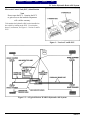
Description of Operation
understand, all WARNINGS and Cautions.
Wheel sensors detect wheel speed. The sensors
generate signals that are transmitted to an Electronic
Control Unit (ECU). If the wheels start lockup, the
ECU sends a signal to the modulator assembly to
regulate the brake pressure of each the affected
wheel.
WARNINGS REFER TO A PROCEDURE
OR PRACTICE THAT, IF NOT ADHERED
TO, COULD RESULT IN INJURY OR
DEATH.
During an ABS stop, a solenoid valve in the
modulator assembly is rapidly pulsed; that is, it
opens and closes several times per second to control
the brake pressure. When this occurs, drivers may
notice a pulsation on the brake pedal.
An ABS indicator lamp on the vehicle dash alerts
the driver to a possible system fault and provides
blink code information to diagnose the system.
Cautions refer to a procedure or practice,
that, if not adhered to, could result in damage
to or destruction of equipment.
If the ABS indicator lamp comes on during normal
vehicle operation, drivers may complete the trip, but
are instructed to have the vehicle serviced as soon as
possible.
In the unlikely event of an ABS system malfunction,
the ABS of the affected wheel will be disabled and
will return to normal braking. The other sensed
wheels will retain their ABS function.
030.1-3
Directory
Previous
Previous
Next
Search
Exit
TC Series Hydraulic Brake ABS System
Electronic Control Unit (ECU) Identification
Note
Do not open the ECU. Opening the ECU
to gain access to the internal components
will void the warranty.
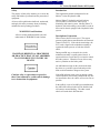
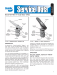
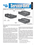
To determine the hydraulic ABS version installed on
the vehicle by looking at the ECU. D version has
three (3) connectors, see Figure 1—Version C and D
ECU.
Figure 1—Version C and D ECU
Figure 1.2—A Typical Meritor WABCO Hydraulic ABS System
030.1-4
Directory
Previous
Previous
Next
Search
Exit
TC Series Hydraulic Brake ABS System
System Components
The following components are the Meritor WABCO
Hydraulic ABS:
• Electronic Control Unit, see Figure 1.3—
Electronic Control Unit
4. Sensors contain brake fluid and must be handled
with appropriate care.
1. Processes sensor signals and generates solenoid
valve commands to reduce maintain or reapply
brake pressure.
2. Mounting locations vary, depending on the
vehicle specifications for the exact location.
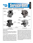
Figure 1.4—Modulator Assembly
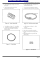
•
Sensor with Molded Socket, see Figure 1.5—
Molded Socket
5. Measures the speed of a tooth wheel rotating
with the vehicle wheel.
6. Produces an output voltage proportional to
wheel speed.
Figure 1.3—Electronic Control Unit
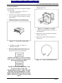
•
Modulator Assembly, see Figure 1.4—
Modulator Assembly
3. Houses the ABS solenoid control valves, (one
inlet valve and one outlet valve per wheel), a
pump motor and two (2) accumulators.
Modulator should not be exposed to impact
loads, excessive vibrations or compressed air
blown into the hydraulic ports.
Figure 1.5—Sensor with Molded Socket
BRAKE FLUID IS FLAMMABLE AND
TOXIC TO SKIN, EYES AND
RESPIRATORY TRACT. SKIN AND EYE
PROTECTION IS REQUIRED. AVOID
REPEATED OR PROLONGED CONTACT.
DRAIN FLUID IN A WELL-VENTILATED
AREA.
030.1-5
Directory
Previous
Previous
Next
Search
Exit
TC Series Hydraulic Brake ABS System
•
Sensor Spring Clip, see Figure 1.6—Sensor
Spring Clip.
•
Holds the wheel speed sensor in close
proximity to the tooth wheel.
7. Two-wire cable with molded-on connector.
Figure 1.6—Sensor Spring Clip
Figure 1.8—Sensor Extension Cables
•
•
Tooth Wheel, see Figure 1.7—Tooth Wheel
A machined or stamped ring mounted to a
machine surface on the hub of each ABSmonitored wheel.
•
Sensor Extension Cables, see Figure 1.8—
Sensor Extension Cables
8. Connector the wheel speed sensor to the ECU.
•
ABS Indicator, see Figure 1.9—ABS
Indicator
9. Located on vehicle dash.
10. Alerts driver to a possible system fault.
11. Used by service personnel to display blink
codes.
12. Meritor WABCO does not provide ABS
indicator lamp.
Figure 1.7—Tooth Wheel
Figure 1.9—ABS Indicator
030.1-6
Directory
Previous
Previous
Next
Search
Exit
TC Series Hydraulic Brake ABS System
Component Removal and Installation
Sensors
•
Sensor Lubrication Specification
Meritor WABCO specifications require a sensor
lubricant to have the following properties.
1. Lube must be mineral oil-based and contain
molydisulfide.
2. Lube should have excellent anti-corrosion and
adhesion properties, and be capable of
continuous function in a temperature range of
3. –40° to +300° Fahrenheit.
Figure 2—Knuckle Mounted Sensor
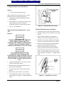
Wheel Speed Sensor Replacement – Front
Axle
Knuckle Mounted Sensor Installation
Removal
2. Install the fasteners used to hold the sensor cable
in place.
1. Connect the sensor cable to the chassis harness.
3. Apply a Meritor WABCO recommended
lubricant to the sensor spring clip and sensor.
CHOCK THE WHEELS TO PREVENT
THE VEHICLE FROM MOVING.
SUPPORT THE VEHICLE WITH SAFETY
STANDS. DO NOT WORK UNDER A
VEHICLE SUPPORTED ONLY BY JACKS.
TO AVOID DAMAGE TO THE
ELECTRICAL SYSTEM OR ABS
COMPONENTS, WHEN WELDING ON AN
ABS-EQUIPPED VEHICLE DISCONNECT
THE POWER CONNECTOR FROM THE
ECU.
4. Install the sensor spring. Make sure the spring
clip tabs are on the inboard side of the vehicle.
5. Push the sensor spring clip into the bushing in
the steering knuckle until the clip stops.
6. Push the sensor completely into the sensor
spring clip until clip contacts the tooth wheel.
7. Fasten the sensor cable with tie wraps every 12
inches. Properly bundle and store excess cable
in the sub frame, see Figure 2.1—Bundle Excess
Cable.
1. Apply the parking brakes. Chock the rear tires
to prevent vehicle movement.
2. Disconnect the fasteners that hold the sensor
cable to other components.
3. Disconnect the sensor cable from the chassis
harness.
4. Remove the sensor from the sensor holder.
5. Twist and pull the sensor to remove from the
sensor bracket, see Figure 2—Knuckle Mounted
Sensor.
Figure 2.1—Bundle Excess Cable
030.1-7
Directory
Previous
Previous
Next
Search
Exit
TC Series Hydraulic Brake ABS System
8. Replace tire and drum if required. Remove
safety stands, lower the vehicle, and remove the
chocks from front tires.
9. Perform a voltage output check to ensure proper
installation, refer to Sensor Output Voltage Test
in troubleshooting section.
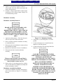
Modulator Assembly
Modulator Assembly Removal
BRAKE FLUID IS FLAMMABLE AND
TOXIC TO SKIN, EYES AND
RESPIRATORY TRACT. SKIN AND EYE
PROTECTION IS REQUIRED. AVOID
REPEATED OR PROLONGED CONTACT.
DRAIN FLUID IN A WELL-VENTILATED
AREA.
1. Apply the parking brakes. Chock the front and
rear tires to prevent vehicle movement.
2. Place a container under the modulator assembly
to catch brake fluid.
3. Disconnect the electrical harness connector from
the modulator assembly.
4. Mark the six brake lines for ease of installation.
Figure 2.2—Modulator Position
2. Torque three (3) mounting nuts to 132 inchpounds.
3. Connect and torque two (2) small brake line
adapters to 108 inch-pounds.
4. Connect and torque four (40) large brake line
adapters to 132 inch-pounds.
5. Disconnect the lines from the modulator
assembly.
Whenever any hydraulic system fitting is
loosened or disconnected, the entire system
must be bled to remove any air.
6. Remove three (3) mounting capscrews, washers,
and nuts that attach the modulator assembly and
bracket assembly to vehicle.
Modulator Assembly Installation
1. Position the modulator assembly and bracket in
place on the vehicle, see Figure 2.2—Modulator
Position.
FAILURE TO BLEED THE SYSTEM
WHENEVER ANY HYDRAULIC SYSTEM
FITTING IS LOOSENED OR
DISCONNECTED WILL ALLOW AIR TO
REMAIN IN THE BRAKE SYSTEM. THIS
WILL CAUSE THE STOPPING
DISTANCE TO INCREASE AND CAN
RESULT IN SERIOUS INJURY.
PROPERLY DISCARD HYDRAULIC
FLUID THAT IS REMOVED FROM THE
BRAKE SYSTEM. HYDRAULIC FLUID
THAT IS COMTAMINATED CAN CAUSE
DAMAGE, LOSS OF BRAKING AND
SERIOUS INJURY.
030.1-8
Directory
Previous
Previous
Next
Search
Exit
TC Series Hydraulic Brake ABS System
2. Master Cylinder Filling and Bleeding
DO NOT USE OR MIX DIFFERENT
TYPES OF HYDRAULIC FLUID. THE
WRONG HYDRAULIC FLUID WILL
DAMAGE THE RUBBER PARTS OF THE
BRAKE CALIPER AND CAN CAUSE
DAMAGE, LOSS OF BRAKING AND
SERIOUS INJURY.
•
Replenish reservoir with the specified brake
fluid.
•
Depress braking pedal 5 times in 5 seconds
using only the stroke between 1/3 of maximum
value.
•
Release the pedal for 5 to 10 seconds Air
bubbles will rise into the reservoir.
•
Repeat all these steps 3 times until sufficient
resistance is felt at the pedal.
3. Brake Circuit Bleeding
•
Fit bleed hose onto one of the bleed screw
nipple.
•
Submerge free end of bleed hose into the
brake fluid of the bleed bottle.
•
Actuate the brake pedal several times then
depress and hold firm.
Hydraulic ABS System Bleeding Procedure
•
This procedure specifies how to bleed the hydraulic
ABS modulator in case of unwanted air in the
modulator and/or suction area of the pump system.
Open the bleed screw of the longest brake
circuit to be bled, often with the RR
•
Allow fluid to flow until no air bubbles or
fluid flows into the bleed bottle.
•
Close the bleed screw prior to the final release
of the brake pedal.
•
Repeat step 3 until fluid flows without any air
bubbles.
•
Repeat step 3 on other three brakes, in order
of longest to shortest circuit from the
modulator, Rl, FR, and FL.
Do not allow brake fluid to touch any painted
surfaces, as it will remove the paint. Brake
fluid may also damage certain non-metal
surfaces. Do not allow fluid to get on brake
pads, shoes, rotors, or drums.
The ignition must remain off throughout the duration
of the manual bleeding of the system, energizing of
the unit during bleeding, unless specified.
Note
During bleeding procedure, reservoir fluid
is not permitted to fall below the MIN
level. Observe the level regularly and
replenish if necessary to the MAX level
marked on the reservoir.
4. Modulator Pump System Filling and Bleeding
•
Pulse the inlet and outlet solenoids of brake
circuit being bled and activate the pump motor
using the ABS switch box. Start with the
longest brake circuit, typically the right rear.
•
Perform conventional bleeding procedure,
section 3, while activating solenoids and pump
motor for all brake circuit.
•
Repeat steps in section 4 until no air is
present, typical four times.
1. Required bleed and fill equipment
•
Clean glass or plastic bottle/receptacle
•
Rubber/plastic bleed hose
•
Suitable bleed spanner
•
Manufacturer’s recommended brake fluid,
approximately ½ gallon
•
Electronic controller or manual modulator
actuator
030.1-9
Directory
Previous
Previous
Next
Search
Exit
TC Series Hydraulic Brake ABS System
Manual Bleeding
BRAKE FLUID IS FLAMMABLE AND
TOXIC TO SKIN, EYES AND
RESPIRATORY TRACT. SKIN AND EYE
PROTECTION IS REQUIRED. AVOID
REPEATED OR PROLONGED CONTACT.
DRAIN FLUID IN A WELL-VENTILATED
AREA.
Do not let the brake master cylinder fluid
level get too low during the bleeding
operation.
Do not release the brake pedal until the
fitting has been tightened. Failure to do so
will allow air bake into the system.
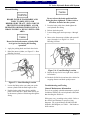
5. Press the brake pedal down, hand tighten the
rear hydraulic line fitting.
6. Release the brake pedal.
7. Loosen fitting again and repeat steps 1 through
6.
8. Move to the front master cylinder and repeat all
steps 1 through 9, see Figure 2.4—Front
Bleeding Location.
1. Apply the parking brake and chock the wheels.
2. Bleed the master cylinder, see Figure 2.3—Rear
Bleeding Location.
Figure 2.4—Front Bleeding Location
9. Repeat all steps for left rear, right front, and left
front brakes.
10. Recheck all fluid levels and test drive vehicle for
stopping distance and brake pedal pressure.
Figure 2.3—Rear Bleeding Location
3. Loosen the fitting at the rear outlet port on the
master cylinder until the fluid begins to flow.
Troubleshooting and Testing
4. Push the brake pedal down slowly until the
pedal reaches the floor. Brake fluid and any air
in the master cylinder will discharge through the
fitting.
There is no regularly schedule maintenance required
for Meritor WABCO D version hydraulic ABS other
than checking the fluid level.
General Maintenance Information
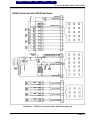
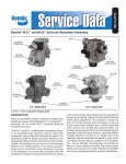
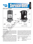
Wiring may vary, according to the vehicle. Refer to
the vehicle specifications for specific wiring
diagrams. For a typical Meritor WABCO 4S/4M
hydraulic ABS diagram, see Table 1—Pin Numbers
and Locations.
030.1-10
Directory
Previous
Previous
Next
Search
Exit
TC Series Hydraulic Brake ABS System
Figure 3—Pin Numbers and Locations
030.1-11
Directory
Previous
Previous
Next
Search
Exit
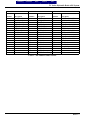
TC Series Hydraulic Brake ABS System
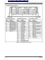
9-Pin ECU Connector
18-Pin ECU Connector
15-Pin ECU Connector
Pin
Circuit
Pin
Circuit
Pin
Circuit
Number
Description
Number
Description
Number
Description
1
2
3
4
5
6
7
8
9
-------------------
Left Front Sensor
Left Front Sensor
Right Rear Sensor
Right Front Sensor
Right Front Sensor
Right Rear Sensor
Left Rear Sensor
Left Rear Sensor
Not Used
-------------------
1
2
3
4
5
6
7
8
9
10
11
12
13
14
15
16
17
18
+ 12 Battery
+ 12 Ignition
Not Used
Not Used
SAE J1587 (-)
SAE J1587 (+)
Not Used
Motor Monitor
Not Used
Not Used
Not Used
Ground
Not Used
Not Used
Jumper
Not Used
Not Used
ABS Indicator Lamp
1
2
3
4
5
6
7
8
9
10
11
12
13
14
15
-------
Left Front Outlet Valve
Left Front Inlet Valve
Ground
Right Front Outlet Valve
Right Front Inlet Valve
Not Used
Left Rear Outlet Valve
Left Rear Inlet Valve
Not Used
Right Rear Outlet Valve
Right Rear Inlet Valve
Retarder
Not Used
Not Used
Pump Relay
-------
Table 1—Pin Numbers and Location
030.1-12
Directory
Previous
Previous
Next
Search
Exit
TC Series Hydraulic Brake ABS System
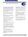
Schematic 1—4S/4M D Version Hydraulic ABS Wiring Diagram
030.1-13
Directory
Previous
Previous
Next
Search
Exit
TC Series Hydraulic Brake ABS System
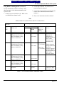
Blink Code Diagnostics
• ABS Indicator Lamp
This lamp, located on the vehicle dash, serves two
purposes:
1. Alerts drivers or service personnel to a possible
fault in the hydraulic ABS, as follows:
•
If the ABS indicator lamp comes on briefly
then goes to off when the ignition is turned on,
there are no active or stored faults in the
hydraulic ABS.
•
If the ABS indicator lamp comes on and stays
on after the ignition is turned on and the
vehicle is driven in excess of 4 mph, there may
be an active fault in the hydraulic ABS.
•
If ABS indicator lamp comes on and stays on
and Goes off after the vehicle is driven more
than 4 mph there may be a stored fault in the
hydraulic ABS.
•
Displays diagnostic blink codes for servicing.
Definitions
•
Blink Code:
A series of blinks or flashes that describe a
particular ABS system condition.
• Blink Code Diagnostics:
The ability of the Meritor WABCO ECU to
sense faults in the ABS system and to define
these faults using blink codes.
•
Blink Code Switch:
A momentary switch that activates blink code
diagnostic capabilities. Usually, it is mounted
under the dash or on the steering column.
• Clearing Fault Codes:
The process of erasing faults from the ECU
memory bank.
• Fault Code:
An ABS condition (fault) detected and stored in
memory by the Meritor WABCO ECU and
displayed by blink code. System faults may be
Active or Stored.
• Active Fault:
A condition that currently exists in the ABS
system; for example, a sensor circuit
malfunction on the left front steering axle. An
active fault must be repaired before additional
faults can be displayed. When an active fault
has been repaired, it becomes a stored fault.
• Stored Fault:
A condition that caused the system to register a
fault but is not currently active. For example, a
loose wire that corrected itself. A stored fault can
also be an active fault that has been corrected.
•
Table 2 describes the method of
distinguishing between active and stored faults
and explains how to clear them.
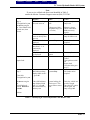
Using Blink Code Diagnostics
•
Observe the steps in Table 2—Identifying D
Version Hydraulic ABS Blink Codes.
030.1-14
Directory
Previous
Previous
Next
Search
Exit
TC Series Hydraulic Brake ABS System
Note
If you receive a blink code that is not identified in Table 2,
contact the Meritor Customer Support center at (800) 535-5560.
Step 1
Turn ignition key on
Do not turn engine
on. Press Blink Code
Switch once, then
release.
Step 2
Response
Status
Action
ABS indicator lamp
Does not come on
Loose or burned Out
bulb
Repair or replace
lamp bulb.
Voltage not within
acceptable range (9.5
to 14 volts)
Measure voltage,
check connections.
Make necessary
repairs.
Check ABS indicator
lamp for blink code.
ABS indictor lamp
comes on briefly then
goes out.
IF 1-1 blink code is
displayed
IF one blink codeother than 1-1—is
continuously
displayed.
IF a series of codes
are displayed
!
!
Stored faults in
system
!
Go to step 3.
ABS indicator lamp
displays blink code 11, goes off
System Okay
No further action
required.
If the ABS indicator
lamp displays blink
code 1-1, goes off,
then comes back on,
and stays on.
System looking for
wheel speed. This
occurs after a sensor
fault.
Drive the vehicle at a
speed of 4 mph.
Once the ECU senses
wheel speed, the
lamp will go off.
System Okay
System fault exists
Repair fault
Step 3
Clear fault
Turn ignition key on.
Do not turn engine
on.
Press blink code
switch. Hold for 3
seconds.
No further action
required.
Go to step 2.
Find blink code on
Table 3
Turn ignition switch
off
Repair fault
Clear the fault (go to
step 3)
Release.
Table 2—Identifying D Version Hydraulic ABS Blink Codes
030.1-15
Directory
Previous
Previous
Next
Search
Exit
TC Series Hydraulic Brake ABS System
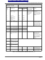
Using Blink Code Diagnostics (continued)
Use the information in Table 3 to identify a fault,
check for proper volt or ohm measurements, and
repair the fault.
1. Identify and record the blink code. Blink codes
are identified in columns 1 and 2.
2. Test the pins indicated. Pin locations to be
tested are listed in column 3.
3. Compare the measurement received against the
correct volt or ohm measurement listed in
column 4.
4. Observe the instructions listed in column 5.
Note
Abbreviations IV are Inlet Valve and OV is Outlet Valve.
Ignition Key On to determine ABS blink
code fault
1
2
Fault
Problem Area
Code
Ignition Key off to test system (except where noted)
1-1
2-1
System Okay
Right Front
Solenoid valve (IV or OV)
failure in modulator, wiring
harness or inside ECU
--15 pin
Left Front
Solenoid valve (IV or OV)
failure in modulator, wiring
harness or inside ECU
15 pin
Right Rear
Solenoid valve (IV or OV)
failure in modulator, wiring
harness or inside ECU
Left Rear
Solenoid valve (IV or OV)
failure in modulator, wiring
harness or inside ECU
Reference to ground
interrupted
15 pin
2-2
2-3
2-4
2-7
3
Connector
Pins to be
Tested
--IV 5 and 3
4
Correct Volt
Ohm Meter
Reading
-----
OV 4 and 3
IV 2 and 3
Inlet valve:
6.5 ± 0.5 ohms
OV 1 and 3
Outlet Valve
3.5 ± 0.5 ohms
5
Action
None required
Check electrical
resistance of
affected valve
wiring to ground at
ECU vehicle
connector and at
modulator plug.
Check voltages at
wiring harness and
connectors.
Voltage of ground
connector should
be approximately 0
volts. Make
necessary repairs.
IV 1 and 3
OV 10 and 3
15 pin
IV 8 and 3
OV 7 and 3
15 pin
3 to chassis
ground
Check ABS ground
connectors. Make
necessary repairs.
Table 3—D Version Hydraulic ABS Blink Codes
030.1-16
Directory
Previous
Previous
Next
Search
Exit
TC Series Hydraulic Brake ABS System
Ignition Key On to determine Ignition Key off to test system (except where noted)
ABS blink code fault
1
2
3
4
5
Fault
Code
Problem Area
Connector
Pins to be
Tested
Correct Volt Ohm
Meter Reading
Action
3-1
Right Front
sensor—Air gap
9-pin
4 and 5
Greater than 0.2
volts AC at 30 rpm
(Rotate wheel ½
revolution per
second)
Check for sensor
adjustment.
Check for excessive
wheel bearing endplay.
Repair or replace as
needed.
3-2
Left Front
sensor—Air gap
Right Rear
sensor—Air gap
Left Rear
sensor—Air gap
Right Front
sensor—Electrical fault
9-pin
1 and 2
9-pin
3 and 6
9-pin
7 and 8
9-pin
4 and 5
500-2000 ohms
Check electrical
resistance of affected
sensor and wiring at
ECU connector and at
harness plugs. Repair
or replace as needed.
Left Front
sensor—Electrical fault
Right Rear
sensor—Electrical fault
Left Rear
sensor—Electrical fault
Right Front
wheel—Erratic wheel
speed
9-pin
1 and 2
9-pin
3 and 6
9-pin
7 and 8
---
---
---
Check for tire size
mismatch or tooth
wheel difference.
Check sensor, sensor
cable, and connector for
intermittent contact.
Repair or replace as
needed.
7-3
Left Front
wheel—Erratic wheel
speed
Right Rear
wheel—Erratic wheel
speed
Left Rear
wheel—Erratic wheel
speed
Retarder Relay
---
---
---
7-4
ABS Warning Lamp
---
---
--
Verify proper
connections to relay.
(see wiring diagram).
Check bulb. Repair or
replace as needed.
3-3
3-4
4-1
4-2
4-3
4-4
5-1
5-2
5-3
5-4
Table 3—D Version Hydraulic ABS Blink Codes (continued)
030.1-17
Directory
Previous
Previous
Next
Search
Exit
TC Series Hydraulic Brake ABS System
Ignition Key On to determine Ignition Key off to test system (except where noted)
ABS blink code fault
1
2
3
4
5
Fault
Code
Problem Area
Connector
Pins to be
Tested
Correct Volt Ohm
Meter Reading
Action
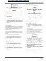
7-7
Recalculation pump
does not switch off.
OR
Recirculation pump
does not switch on (low
level with act.)
Recirculating pump
motor locked.
18-pin
8 and 12
0 volt
8 and 12
Turn Ignition on
12 volts DC
Check the recirculation
pump wiring, the pump
relay, fuse and pump
connections. Repair or
replace as needed.
18-pin
Link pins
2 and 8
Turn Ignition on
8-1
No voltage
18-pin
1 and 2
Turn Ignition on
12 volts DC
8-2
Continuous supply to
ECU with ignition off.
18-pin
5 and 12
0 volt
8-3
Internal ECU fault
---
---
---
7-8
Excessive current
failure. If pump does
not run when pins are
linked, replace
modulator assembly.
Check the valve relay,
fuse, and wiring.
Repair or replace as
needed.
Check for proper wiring
connections. Make
necessary repairs.
Replaced ECU
Table 3—D Version Hydraulic ABS Blink Codes (continued)
Testing the System
TO PREVENT SERIOUS EYE INJURY,
ALWAYS WEAR EYE PROTECTION
WHEN PERFORMING VEHICLE
MAINTENANCE OR SERVICE.
EXHAUST GAS CONTAINS POISON.
WHEN TESTING A VEHICLE WITH THE
ENGINE RUNNING, TEST IN A WELLVENTILATED AREA.
TO AVOID SERIOUS PERSONAL
INJURY, KEEP AWAY, AND KEEP TEST
EQUIPMENT AWAY, FROM ALL
MOVING OR HOT ENGINE PARTS.
•
Reference and observe the vehicle
manufacturer’s Warning, Cautions, and
Service Procedures.
•
When testing, set the parking brake and place
the gear selector in NEUTRAL (manual
transmission) or PARK (automatic
transmission) unless otherwise directed.
Test Equipment Volt-Ohm Meter (VOM)
Use of a VOM with automatic polarity sensing is
recommended. This eliminates the concern of the
polarity of the meter leads during voltage
measurements.
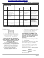
System Requirements and Component Tests
• Tire Size Range
For proper hydraulic ABS operation, front and rear
tire sizes must be within 16% of each other.
Contact the Meritor WABCO Customer Support
Center at (800) 535-5560 if you plan a tire size
difference of more than 8%.
Calculate the tire size with the following equation:
RPM Steer
% Difference = { ————— – 1} x 100
RPM Drive
RPM = Tire Revolutions Per Mile
030.1-18
Directory
Previous
Previous
Next
Search
Exit
TC Series Hydraulic Brake ABS System
Sensor Adjustment
When troubleshooting or testing the ABS
system, do not damage the connector
terminals.
Do not pry or push sensors with sharp
objects.
Voltage Check
Note
Sensor will self-adjust during wheel
rotation.
No gap is allowed at installation. During
normal operation, a gap not exceeding
0.04 inch is allowable.
Voltage must be between 9.5 and 14 volts for the 12
volt hydraulic ABS to function properly.
• To check voltage
1. Turn ignition on.
2. Check for proper voltage between pins (12 and
1) and (12 and 2) on the 18 pin connector.
3. If voltage is not between 9.5 and 14 volts, verify
proper wiring connections. Make corrections as
required.
ABS Indicator
To adjust the sensor, push the sensor in until it
contacts the tooth wheel.
Sensor Output Voltage Test
•
Sensor output voltage must be at least 0.2
volts AC at 30 rpm. Test the sensor output
voltage.
If the ABS indicator lamp does not come on after the
ignition is turned on, or it comes on but does not go
out after 3 seconds, check all ABS fuses or circuit
breakers and replace.
1. Turn ignition off.
Check the wiring to the ABS diagnostic switch and
the indicator lamp. Repair, or replace the wiring as
required.
• When checking the indicator lamp
3. Put blocks under the front and rear tires to keep
the vehicle from moving.
2. Disconnect the ECU. Measure voltage at the
pins on the ECU connector, disconnect the
sensor from the sensor extension cable.
1. Check voltage potential at the lamp socket.
2. Check continuity of the wires to the socket.
3. Replace bulb.
ABS Diagnostic Switch
•
When testing the ABS diagnostic switch
1. Check the resistance between the terminals
while cycling the switch.
2. Check the continuity of the wires to the switch
(pins 5 and 12) and (6 and 12) on the 18 pin
connector.
CHOCK THE WHEELS TO PREVENT
THE VEHICLE FROM MOVING.
SUPPORT THE VEHICLE WITH SAFETY
STANDS. DO NOT WORK UNDER A
VEHICLE SUPPORTED ONLY BY JACKS.
4. Raise the vehicle off the ground. Put safety
stands under the axle.
5. Rotate wheel by hand at 30 rpm (1/2 revolution
per second).
6. Measure the voltage at the pins, see Table 4—
Sensor Check Pins.
030.1-19
Directory
Previous
Previous
Next
Search
Exit
TC Series Hydraulic Brake ABS System
Sensor Resistance
•
The sensor circuit resistance must be between
500 and 2000 ohms. Measure resistance at the
sensor connector, or at the pins on the ECU
connector.
•
8. Measure output at the pins, see Table 4—Sensor
Check Pins.
7. Turn ignition off.
•
To measure resistance at the sensor connector,
disconnect the sensor from the sensor
extension cable.
To measure resistance at the pins on ECU
connector, disconnect the ECU from the sensor
extension cable.
Sensor
Pins ( 9 pin Connector )
Left Front
Right Front
Left Rear
Right Rear
1 and 2
4 and 5
7 and 8
3 and 6
Table 4—Sensor Check Pins
•
If measurement is not between 500 and 2000
ohms, replace the sensor.
Back to Top
030.1-20