1
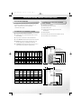
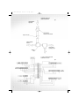
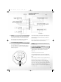
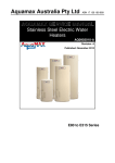
1845 Tech Manual.qxd
23/11/05
1:20 pm
Page 2
EXCELSIOR
UNVENTED WATER HEATERS
INSTALLATION MANUAL
Design for living
1845 Tech Manual.qxd
23/11/05
1:21 pm
Page 3
TECHNICAL DATA & INSTALLATION
INSTRUCTIONS FOR EXCELSIOR DIRECT &
INDIRECT UNVENTED WATER HEATERS
WITH EXTERNAL EXPANSION TANK
IMPORTANT NOTICE FOR INSTALLATION
READ THESE INSTALLATION AND MAINTENANCE
INSTRUCTIONS BEFORE COMMENCING
UNVENTED CYLINDERS ARE DESIGNED TO BS STANDARD AND
INSTALLED TO RELEVANT BUILDING REGULATIONS
Fabdec Ltd is one of the worlds leading unvented water heater
manufacturers.
THE RELEVANT REGULATIONS ARE
Your water heater is made from Duplex Stainless Steel, which is one
of the toughest and best grades of steel currently available.
ENGLAND & WALES – BUILDING REGULATION G3
Each unit has been individually tested and inspected to industry
standard.
Your water heater uses advances in technology and innovative
techniques to provide you with a high performance water heater at
the best price possible.
No other type of water heater can provide all of the benefits that
can be achieved from unvented units such as the Excelsior
Unvented Water Heater.
SCOTLAND – TECHNICAL STANDARD P3
NORTHERN IRELAND – BUILDING REGULATION P5
AFTER INSTALLATION THE BENCHMARK LOG BOOK MUST BE
COMPLETED AND LEFT ALONG WITH THESE INSTRUCTIONS WITH
THE HOUSEHOLDER FOR FUTURE REFERENCE.
INSTALLATION INSTRUCTION MANUAL
TO BE LEFT WITH THE UNIT
INSTALLATION INSTRUCTIONS
Siting the Excelsior Unit
p4
Check water pressure & flow rates
p4
Connecting the water supply
p5
Cold water valve
p5
Drain tap
p5
Pipework to taps
p5
Secondary circulation
p5
Wiring
p7
Fitting immersion heaters
p7
Fitting the thermal cut out & primary connections
p7
Tundish
p8
Commissioning the Excelsior Unit
p8
External expansion tank
p8
Scale
p8
Draining
p8
Discharge pipework
p8
G3 Requirement
p9
Problem solving
p10
Spares
p10
Part component references
p10
Guarantee
p11
DIAGRAMS
CONTENTS
SPECIFIERS GUIDE
2
Dimensional data for DH / IDH
range of water heaters
p3
Typical installation of a DH tank
p5
Typical installation of a IDH tank
p5
The law and unvented
p3
Secondary circulation connection
p6
The benefits of unvented systems
p3
2 x 2 port (S-plan) valve system
p6
The benefits of Excelsior Unvented Water Heaters
p3
2 port valve + 3 port mid position valve (y-plan)
p7
Standard energy losses
p4
Immersion heater
p7
What is supplied with Excelsior?
p4
Schematic discharge pipe arrangement
p8
1845 Tech Manual.qxd
23/11/05
1:21 pm
Page 4
EXCELSIOR WATER HEATER SPECIFIERS GUIDE
THE LAW AND UNVENTED
THE BENEFITS OF EXCELSIOR UNVENTED
WATER HEATERS
It is legal to fit an Unvented Unit into any property. UK water
byelaws were amended to allow this change. There is no
● Expansion vessel supplied
longer a requirement to have an old-fashioned
● Annual inspection as per warranty
“Tank-in-the-Roof” system.
● Duplex Stainless Steel
● Operates at 3bar, which is higher than some other
unvented units
THE BENEFITS OF UNVENTED SYSTEMS
● High quality finish
● A real Power Shower without a noisy pump
● Has one of the lowest heat losses for maximum economy
● No tanks in the roof – no ballcocks to jam or leak – no noise
● No sacrificial anode - low maintenance
from tank filling
● All your water – hot and cold – is direct from the mains
● Site the Excelsior unvented water heater wherever convenient
● Excelsior fills your bath in minutes and will run two at the
same time (subject to good plumbing and flow rates)
● The Excelsior unit works off electricity (economy 7) or any oil
or gas fired boiler (not suitable for solid fuel boilers)
574
45
Note:
All External Exposed
Pipework is 22mm Diameter
316L Stainless Steel
N/A
283
233
230
N/A
928
973
618
188
558
483
357
230
521
150
1056
1101
737
188
558
483
357
230
640
175
1213
1258
883
188
758
683
458
230
786
215
1455
1500
1108
188
758
683
507
230
1011
255
1723
1768
1356
188
758
683
608
230
1259
305
1999
2044
1613
188
758
683
608
230
1516
45
130
Direct Heat Exterior Reference Dimensions
Overall
Height
mm
P&T
Valve
mm
Top
Heater
mm
Bottom
Heater
mm
80
636
694
347
N/A
250
230
130
928
986
618
521
188
230
150
1056
1114
737
640
188
230
175
1213
1271
883
786
188
230
215
1455
1513
1108
1011
188
230
255
1723
1781
1356
1259
188
230
305
1999
2057
1613
1516
188
230
Dimensional data for Indirect Heat/Direct Heat range of water heaters
All External Exposed
Pipework is 22mm Diameter
316L Stainless Steel
Water
In
mm
Tank Height
Tank
Height
mm
574
Note:
Overall Height
Reference
Volumes
litres
P & T Vlve
188
Top Coil
347
Bottom Coil
681
Top
Heater
mm
P & T Vlve
636
Water
In
mm
Twin Thermostat
80
Bottom
Temp
Coil
Monitor
mm
mm
Water Inlet
Top
Coil
mm
Top Heater
Bottom
Heater
mm
Bottom Heater
P&T
Valve
mm
Water Inlet
Overall
Height
mm
Bottom Heater
Tank
Height
mm
Tank Height
Reference
Volumes
litres
Overall Height
Indirect Heat Exterior Reference Dimensions
3
1845 Tech Manual.qxd
23/11/05
1:22 pm
Page 5
● 1 Element on IDH indirect models up to 305 litres and 80 litre
STANDARD ENERGY LOSSES
DH direct model
The heat loss of each Excelsior Unvented Unit while
maintaining the temperature of the stored water at 65 degrees
Celsius. (See performance table below).
1) Tests carried out by BBA. Slight variations may occur with
changes to water mains supply pressure
● 2 Elements on DH direct models from 130 up to 305 litres.
Additional elements from 215 to 305 litres are available on
request.
● Cold-water control valve comprising line strainer, check valve,
pressure reducing valve set to 3 bar
Excelsior Performance
● Expansion relief valve with non return valve set at 6 bar
Nominal
Heat up
Heat up
Reheat
Reheat
Heat loss in
Capacity Model IDH Model DH Model IDH Model DH
24 hrs
Litres
Mins
Mins
Mins
Mins
kw/hr
● Tundish 15mm x 22mm F x F
80
33
64
23
53
1.12
130
28
115
21
90
1.50
150
33
138
24
104
1.82
175
215
27
35
167
212
24
30
124
153
2.10
2.64
● Motorised valve (indirect units only)
● Cylinder thermostat-factory fitted to cylinder, maximum setting
255
42
263
35
184
2.73
305
50
313
42
220
2.88
2) These figures relate to a 45 degree differential between the
stored water and ambient temperature
● Temperature / Pressure relief valve set at 90 degrees Celsius
and 7 bar pressure relief (factory fitted)
85 degrees Celsius (indirect units only)
● Thermal cut out set to operate at 87 degrees Celsius plus or
minus 3 degrees (indirect units only)
● Expansion vessel capacity ranges as shown in the table below: -
WITH AN EXCELSIOR UNVENTED CYLINDER
THE FOLLOWING IS SUPPLIED AS STANDARD
Before commencing installation check that all the components of
Tank Size
Expansion Tank Required
80 to 130 Litres
12 Litres
150 to 215 Litres
18 Litres
255 to 305 Litres
25 Litres
your Excelsior Unit are contained in the kit.
● 3KW Incoloy 825 heating element-incorporating thermostat to
70 degrees Celsius and resetable safety cut out set at 80
degrees Celsius
EXCELSIOR UNVENTED INSTALLATION INSTRUCTIONS
WARNING: Under no circumstances must the factory fitted temperature pressure relief valve be removed. This will totally invalidate any
guarantee or claim. The cold-water inlet valve assembly must be fitted or the Excelsior unit will not perform satisfactorily.
DO NOT ATTEMPT TO VENT THE PRIMARY CIRCUIT THROUGH THE EXCELSIOR UNIT.
All boilers should be installed to manufacturers instructions and the primary circuit through the Excelsior unit must be pumped.
SITING THE EXCELSIOR UNIT
The unit can be placed anywhere convenient. Because it is
connected directly to the mains water supply it is equally efficient
on any floor – ground, first or second. Avoid areas that may be
subject to frost. Try to keep pipe runs as short as possible for
We suggest 1.5 bar pressure & 15 litres / minute flow rate to be the
minimum requirements for satisfactory operation. Less than this
the unit will still operate but you will not be able to run two, or
more, outlets at the same time. 85% of all U.K homes have more
maximum economy, especially hot water discharge pipes running
than 2-bar pressure.
down from the Excelsior unit.
The mains supply must not exceed 16 bar. If it does a special
pressure-reducing valve will be required.
The unit can be fitted into a conventional airing cupboard and
4
CHECK WATER PRESSURE & FLOW RATES
does not require any additional insulation.
Important Note: - Stainless Steel Tectile push fit elbows are fitted
ALL EXCELSIOR UNITS MUST BE STORED VERTICALLY
as standard to all Excelsior Cylinders.
1845 Tech Manual.qxd
23/11/05
1:22 pm
Page 6
CONNECTING THE WATER SUPPLY
DRAIN TAP
● Pipework is not supplied
A drain tap to drain the unit must be fitted to the cold-water inlet
● All pipework should be installed using good plumbing practice.
pipe somewhere between the Excelsior unit and the cold water
valve assembly and at as low a level as possible, see fig. 1.
We recommend 22mm mains cold water supply is used.
● Install a Stop Cock Valve before the cold water inlet assembly on
the incoming mains water supply so the unit can be isolated if
PIPEWORK TO TAPS
required.
Ideally a 22mm pipe run should supply the outlets throughout the
property with short lengths (max 1 metre) runs of 15mm going to
baths, showers, and basin taps. Smaller bore pipe can be used to
suit taps.
COLD WATER VALVE
The combined cold water valve (supplied) can be connected
anywhere on the cold water mains prior to the unit. It can even be
SECONDARY CIRCULATION
located at a point near to where the mains supply enters the
This is particularly easy to fit on the Excelsior units; a Swept Tee
premises if this is more convenient. When installing the cold water
(not supplied) is needed for all indirect models if secondary
valve, ensure that the arrow is pointing in the same direction as the
circulation is required, see page 6 fig. 3 for fitting. A non-return
mains water supply flow when connecting, see fig 2.
valve (not supplied) must be fitted to prevent backflow. You will
need a pump to circulate the hot water (not supplied). The return
The cold water balancing port, on the valve, allows you to connect
feed is in 15mm pipe and all work can be done on site.
the cold water mains to the rest of the property thus giving
balanced pressure throughout. If this facility is not required leave
the cap on.
Typical Indirect Tank installation using external expansion vessel
WATER FLOW
HOT WATER OUTLET
Fig.1
EXPANSION VESSEL
(WALL MOUNTED)
7 BAR / 90 DEGREES
PRESSURE &
TEMPERATURE
RELIEF VALVE.
WATER FLOW
TO COIL INLET
PRIMARY FLOW
TUNDISH
WATER FLOW TO
MANFOLD VIA
FLEXIBLE HOSE
PRIMARY RETURN
WATER FLOW
FROM COIL INLET
TWIN
THERMOSTAT
SECONDARY
RETURN FLOW
WATER FLOW
TO OVERFLOW
PRESSURE
6 BAR
EXPANSION REDUCING VALVE
SET AT 3 BAR
RELIEF
VALVE
IMMERSION
HEATER
WATER INLET
WATER FLOW
INLET SIDE OF TANK
SWEPT TEE
DRAIN
COCK
Cold water inletvalve assembly
BALANCED
COLD WATER
OUTLET
WATER FLOW
FROM EXPANSION
TANK TO 22MM
FEMALE THREAD
BEHIND COVER
BLANKED
PORT
6 BAR
EXPANSION
RELIEF
VALVE
PRESSURE REDUCING
VALVE
SET AT 3 BAR
Fig.2
WATER FLOW INLET SIDE OF TANK
WATER FLOW FROM EXPANSION
TANK TO 22MM FEMALE THREAD
BEHIND COVER
BLANKED
PORT
5
1845 Tech Manual.qxd
23/11/05
1:23 pm
Page 7
SECONDARY CIRCULATION
CONNECTION DIAGRAM
Fig.3
2 * 2 PORT (S-PLAN) VALVE SYSTEM
GUIDANCE LAYOUT ONLY
Fig.4
6
1845 Tech Manual.qxd
23/11/05
1:23 pm
Page 8
2 PORT VALVE + 3 PORT MID POSITION
VALVE (Y-PLAN) SYSTEM
GUIDANCE LAYOUT ONLY
Fig.5
WIRING
As our heating element is Incoloy 825 and is fitted with a cut-out
All electrical wiring should be carried out by a registered electrical
and thermostat for safety, a non-standard 13/4" boss is fitted to the
contractor and must conform to the latest IEE wiring regulations
unit. Replacements can only be obtained from your authorised
dealer or Fabdec Ltd.
Do not switch the power on until the unit has been filled with
water and all wiring has been earthed, see Fig. 4 and 5.
All our heating elements have a built in manual reset cut-out. This
will operate if the immersion heater thermostat fails.
FITTING IMMERSION HEATERS
These are supplied as standard
WARNING: Ensure that the immersion heater thermostat is set
at 60 degrees Celsius.
An ’O’ ring is supplied as the seal and must be fitted against the
flange of the element. Take care not to cross thread and DO NOT
USE any other type of seal.
FITTING THE THERMAL CUT-OUT &
PRIMARY CONNECTIONS
The motorised valve supplied and the thermal cut-out (Hi limit
stat) must be fitted to the primary flow. Use compression
fittings only.
Operation of the cut-out and motorised valve
To comply with BBA regulations and to prevent the temperature
reaching 100 degrees Celsius the thermal cut-out supplied must be
E
fitted.
N
L
The thermal cut-out is wired in series to the cylinder thermostat.
When the thermal cut-out senses an abnormal rise in
temperature in the primary flow the electrical supply to the
motorised valve will be cut, and the valve will be in the closed
position thus cutting of the primary water from the boiler to the
indirect coil in the cylinder. If this occurs it must be reset
manually. If the thermal cut-out operates check the cylinder stat
and / or boiler stat.
7
1845 Tech Manual.qxd
23/11/05
1:24 pm
Page 9
TUNDISH
DRAINING
The tundish supplied must be fitted visible to the occupier. The
Switch off electrical power to immersion heaters and/or shut down
discharge pipe must be 22mm copper pipe. Regulations do not
the boiler. Close the stopcock valve to isolate the Excelsior unit.
permit more than 3 x 90-degree bends between the Excelsior unit
and the outflow. Between the temperature & pressure relief valve
Attach hosepipe to the drain cock having sufficient length to take
and the first 90-degree bend there must be a fall of at least
water to a suitable discharge point.
300mm. The fall of the pipework must be continuous and the pipe
should terminate in the gully or be bent backwards onto an
outside wall, in a place where discharge cannot be injurious to
Open drain cock
Open hot water tap nearest Excelsior unit.
persons.
If water fails to drain from Excelsior unit, vent the system by
If you need to site the Excelsior unit In the middle of the house
opening the temperature pressure relief valve.
your discharge pipe to the tundish can be as far away as 9m, which
in most cases is enough to run the final discharge point. After 9m,
increase the pipe size to a greater diameter than 22mm and
accordingly for subsequent 9m lengths, see table 1 on page 10.
SCHEMATIC DISCHARGE
PIPE ARRANGEMENT
COMMISSIONING THE EXCELSIOR UNIT
Fig.6
Switch on electricity to the immersion heater(s) (Direct system) or
switch on the boiler (Indirect system). Refer to the boiler
manufacturers instructions on commissioning.
Bring the unit to its maximum temperature setting of approx. 60
degrees Celsius. You should, on operating the water taps, have a
good flow of hot and cold water assuming adequate water is
supplied to the Excelsior unit.
Check the water does not discharge via the tundish pipework
during heating.
Recheck all fittings/joints for possible leaks.
On completion of the installation, before turning on the mains
water supply ensure that all residual materials are removed by
means of flushing the system with a "fernox" type cleaner or
equivalent.
EXTERNAL EXPANSION TANK
This smaller tank is connected to the cold-water inlet side of the
DISCHARGE PIPEWORK
vessel. Mount the tank according to separate manufacturers
instructions provided with the External Expansion Tank.
See fig 1 page 5.
It is a requirement of Building Regulations that any discharge from
an unvented system is conveyed to where it is visible, but will not
cause danger to persons in or about the building. The tundish and
SCALE
discharge pipes should be fitted in accordance with the
requirements and guidance notes of Building Regulations. Building
In hard water areas lower water temperatures can result in less
scale being deposited.
If water softener is used it should be capable of flows of approx. 50
lt/min, this will maintain maximum performance of the Excelsior
unit.
8
Regulation G3 Requirements and guidance section 3.9 reproduced
in the following sections.
Information Sheet No. 33 available from the British Board of
Agreement gives further advice on discharge pipe installation. For
discharge pipe arrangements not covered by G3 Guidance or BBA
If no descaler or softener is used then the heating element(s) will
Info Sheet No. 33 advice should be sought from either your local
need descaling periodically for maximum efficiency.
Building Control Officer or Fabdec Ltd.
1845 Tech Manual.qxd
23/11/05
1:24 pm
Page 10
G3 REQUIREMENT
areas etc. are acceptable providing that where children may
‘…there shall be precautions…to ensure that the hot water
play or otherwise come into contact with discharges a wire
discharged from safety devices is safely conveyed to where it is visible
cage or similar guard is positioned to prevent contact, whilst
but will not cause danger to persons in or about the building.’
maintaining visibility.
iii) discharges at high level; e.g into a metal hopper and metal
G3 GUIDANCE SECTION 3.9
The discharge pipe (D1) from the vessel up to and including
tundish is generally supplied by the manufacturer of the hot water
storage system. Where otherwise the installation should include
the discharge pipe (s) (D1) from the safety device(s). In either case
the tundish should be vertical located in the same space as the
down pipe with the end of the discharge pipe clearly visible
(tundish visible or not) or onto a roof capable of withstanding
high temperature discharges of water and 3m from any
plastics guttering system that would collect such discharges
(tundish visible.)
iv) where a single pipe serves a number of discharges, such as in
unvented hot water storage system and be fitted as close as
blocks of flats, the number served should be limited to not
possible and within 500mm of the safety device e.g the
more than 6 systems so that any installation discharging can be
temperature relief valve.
traced reasonably easily. The single common discharge pipe
The discharge pipe (D2) from the tundish should terminate in a
safe place where there is no risk to persons in the vicinity of the
discharge, preferably be of metal and:
should be at least one pipe size larger than the largest
individual discharge pipe (D2) to be connected. If unvented
hot water storage systems are installed where discharges from
safety devices may not be apparent i.e. in dwellings occupied
a. be at least one pipe size larger than the nominal outlet size of
by blind, infirm or disabled people, consideration should be
the safety device unless it’s total equivalent hydraulic resistance
given to the installation of an electronically operated device to
exceeds that of a straight pipe 9m long ie. discharge pipes
warn when discharge takes place.
between 9m and 18m equivalent resistance length should be
at least two sizes larger, than the nominal outlet size of the
safety device between 18 and 27m, at least 3 sizes larger and so
on. Bends must be taken into account in calculating flow
Note: The discharge will consist of scalding water and steam.
Asphalt, roofing felt and non-metallic rainwater goods may be
damaged by such discharges.
resistance. Refer to Table 1 overleaf and fig. 6.
WORKED EXAMPLE OF DISCHARGE PIPE SIZING
An alternative approach to sizing discharge pipes would be to
The example below is for a G1/2 temperature relief valve with a
follow BS 6700:1987 specification for design installation, testing
discharge pipe (D2) having 4 No elbows and length of 7m from the
and maintenance of services supplying water for domestic use
tundish to the point of discharge.
within buildings and their curtilages, Appendix E, section E2
From table 1: (overleaf )
and table 21.
Maximum resistance allowed for a straight length of 22mm copper
b. have a vertical section of pipe at least 300mm long, below the
discharge pipe (D2) from G1/2 temperature relief valve is 9.0m
tundish before any elbow or bends in the pipework.
Subtract the resistance for 4 No 22mm elbows at
c. be installed with a continuous fall.
d. have discharges visible at both the tundish and the final point
0.8m each = 3.2m
Therefore the permitted length equates to 5.8m
of discharge but where this is not possible or is practically
5.8m is less than the actual length of 7m therefore calculate the
difficult there should be clear visibility at one or other of these
next largest size.
locations.
Maximum resistance allowed for a straight length of 28mm pipe
(D2) from a G1/2 temperature relief valve equates to 18m
Examples of acceptable discharge arrangements are:
Subtract the resistance of 4 No 28mm elbows at
i)
ideally below a fixed grating and above the water seal in a
trapped gully.
ii) downward discharges at low level; i.e. up to 100mm above the
external surfaces such as car parks, hard standings, grassed
1.0m each = 4.0m
Therefore the maximum permitted length equates to 14m
As the actual length is 7m a 28mm (D2) copper pipe will
be satisfactory.
9
1845 Tech Manual.qxd
23/11/05
1:26 pm
Page 11
TABLE 1 – SIZING OF COPPER DISCHARGE PIPE (D2) FOR COMMON T&P RELIEF VALVE SIZES
Valve outlet Size
Minimum size of
discharge pipe D1
Minimum size of
discharge pipe D2
from tundish
G1/2
15mm
G3/4
G1
22mm
28mm
Maximum resistance
allowed, expressed as a
length of straight pipe
(i.e. no elbows or bends)
Resistance created by
each elbow or bend
22mm
up to 9m
0.8m
28mm
up to 18m
1.0m
35mm
up to 27m
1.4m
28mm
up to 9m
1.0m
35mm
up to 18m
1.4m
42mm
up to 27m
1.7m
35mm
up to 9m
1.4m
42mm
up to 18m
1.7m
54mm
up to 27m
2.3m
PROBLEM SOLVING
Check current amps drawn by the heater, should be approx. 15
No water in tap from the Excelsior Unit
amps. If heating element fails to operate, change the complete
heating element assembly.
Check that mains supply is on.
Check that the line strainer is not blocked
Important. In the event of an over heat situation reset all
thermal cutouts.
Check that the combination valve has been fitted so that the arrow
on it faces in the direction of the water flow.
If the water at the hot tap is cold
Boiler (indirect): Ensure that the boiler has been switched on and
If hot water discharges from Tundish
WARNING: Do not turn the mains water supply off - switch off (1)
power to immersion heaters (Direct) or (2) shut down heating
boiler (Indirect)
working correctly.
Check that no air blocks have occurred in the primary system
Check the following are all connected correctly
If hot water discharges from the tundish on indirect models there
could be a fault with the thermal cut out, cylinder thermostat or
temperature pressure relief valve. On a direct model the fault could
Cylinder Stat
lie with the heating element thermostat. We recommend you call
Thermal cut out (Reset by pushing red button)
your installer or Fabdec ltd.
Motorised valve
Boiler thermostat (max setting 82 degrees Celsius)
Boiler thermal cut out (if fitted)(Reset by pushing red button)
SPARES
When ordering replacement parts the serial number on the unit
should be quoted.
Direct (Electric) Models
WARNING: Isolate unit at main electric supply before opening
PART/COMPONENT REFERENCES
heating element cover.
Ensure that power is available to the element from the electric
mains and that the isolator is on. If there is power to the element
and the element fails to operate check as follows:
Check that the thermal cut out on the elements have not operated.
If they have, reset by pressing the red button. If they cut out again
as the water heats up the cylinder thermostat has failed and needs
replacing. Fit a new thermostat and reset the thermal cut out.
With power on and the thermal cut out reset check the output
terminal on the thermostat. If the circuit cannot be completed, the
thermostat and/or cut out needs replacing.
10
Expansion Vessel Kit (12 Litre) -
951923
Expansion Vessel Kit (18 Litre) -
951924
Expansion Vessel Kit (25 Litre) -
951925
Motorised Valve -
951878
Immersion Heater -
951860
Temp/pressure Relief Valve -
951858
Twin Thermostat -
951879
WARNING: Should the factory fitted temperature and pressure
relief valve be tampered with your guarantee will be invalidated.
Neither the distributor nor manufacturer shall be responsible for
any consequential damage howsoever caused.
1845 Tech Manual.qxd
23/11/05
1:26 pm
Page 12
GUARANTEE
The Excelsior Duplex vessel carries a full 25-year cylinder guarantee against faulty materials or manufacture provided that:
• It has been correctly installed as per the Installation Manual and all the relevant regulations and codes of practice in force at the time.
• It has not been modified in any way, other than by Fabdec Ltd
• It has not been misused, tampered with or subjected to neglect
• It has only been used for the storage of potable water
• It has not been subject to frost damage
• The unit has been serviced annually
• The logbook has been filled in after each annual service
• Within 30 days of purchase the user completes and returns the certificate supplied to register the product.
Please note that invoices for servicing will be requested to prove that the unit was serviced annually
5 year guarantee available on all components except immersion heater and cylinder thermostat (Which carry a two year guarantee). However, this is
subject to the Benchmark logbook having a regular service stamp by a qualified unvented installer.
Exclusions – The guarantee does not cover: -
• The effects of large scale build up
• Any labour charges associated with replacing the unit or outs parts
• Any consequential losses caused by the failure or malfunction of the unit
GUIDANCE IN THE EVENT OF A PROBLEM
If you have a problem in the first instance contact the plumber who fitted the unit. There after contact the plumber who carries out the annual
servicing for you.
If your Excelsior unit develops a leak we will supply you with a new one. We ask for a nominal up front payment to prevent fraud. We will require the
original unit to be returned to us for inspection along with a copy of your logbook. When it is confirmed that it has failed within the terms of the
warranty the up front payment will be refunded.
If a component fails within either the five or the two-year guarantee period we will send you a new one without any up front charge. Credit card
details may be taken to prevent fraud. We ask you to post the faulty part back to us within one month by recorded delivery.
✁
Due to our ongoing product development policy we reserve the right to alter specifications without prior notice.
EXCELSIOR GUARANTEE REGISTRATION
To be completed by the owner of the property
By completing and returning this form we will register you as the
Please indicate as appropriate.
owner of this Exelsior model.
These details, of your purchase and installation, will assist our
1. Which Excelsior model have you installed?
ongoing product development, and enable us to deal with any
queries you may have should you need to contact our Customer
Service department in the future.
2. Where in the property has the Excelsior unit been installed?
Serial no. of the unit:
Date of Installation:
Users Name:
Address:
3. What source of central heating is used?
Oil
Telephone No.
Gas
Electricity
Solid Fuel
4. Which of the following best describes the type of Installation?
New Build
Refurbishment
Direct Replacement
Design for living
11
1845 Tech Manual.qxd
23/11/05
1:20 pm
Page 1
UK Head Office
Fabdec Ltd
Grange Road Ellesmere
Shropshire SY12 9DG UK
Tel: + 44 (0) 1691 627200
Sales/Service Tel: + 44 (0) 1691 627210
Fax: + 44 (0) 1691 627222
Email: excelsior.sales@fabdec.com
Website: www.fabdec.com
AFFIX
STAMP
HERE
Fabdec Ltd
Grange Road
Ellesmere
Shropshire
SY12 9DG
UK