1
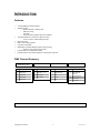
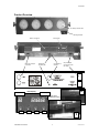
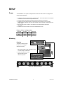
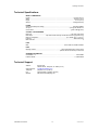
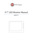
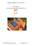
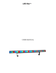
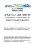
LED-BANK4 COLORbank™ 4 USER MANUAL CHAUVET, 3000 N 29th Ct, Hollywood, FL 33020 U.S.A (800) 762-1084 – (954) 929-1115 FAX (954) 929-5560 www.chauvetlighting.com 2006-04-18/16:44 Table of Content BEFORE YOU BEGIN....................................................................................................................................................... 3 WHAT IS INCLUDED .......................................................................................................................................................................................................... 3 UNPACKING INSTRUCTIONS .............................................................................................................................................................................................. 3 AC POWER ..................................................................................................................................................................................................................... 3 SAFETY INSTRUCTIONS .................................................................................................................................................................................................... 3 INTRODUCTION ............................................................................................................................................................... 4 FEATURES ....................................................................................................................................................................................................................... 4 DMX CHANNEL SUMMARY ............................................................................................................................................................................................... 4 PRODUCT OVERVIEW....................................................................................................................................................................................................... 5 SETUP .............................................................................................................................................................................. 6 POWER ........................................................................................................................................................................................................................... 6 MOUNTING ...................................................................................................................................................................................................................... 6 OPERATING INSTRUCTIONS .......................................................................................................................................... 7 USING THE CONTROL PANEL............................................................................................................................................................................................. 7 Control Panel Modes & Functions ........................................................................................................................................................................... 7 MASTER/SLAVE & STAND ALONE ..................................................................................................................................................................................... 8 Built in programs detailed ........................................................................................................................................................................................ 8 DMX CONTROL MODE ..................................................................................................................................................................................................... 9 Daisy Chain Connection..................................................................................................................................................................................... 9 DMX mode setup................................................................................................................................................................................................ 9 About DMX addressing .................................................................................................................................................................................... 10 CONTROLLING MULTIPLE COLORBANKS™ AS ONE DEVICE ............................................................................................................................................ 10 APPENDIX ...................................................................................................................................................................... 11 DMX PRIMER ................................................................................................................................................................................................................ 11 Fixture Linking .................................................................................................................................................................................................. 11 DMX CHANNEL VALUES ................................................................................................................................................................................................ 12 RETURNS PROCEDURE .................................................................................................................................................................................................. 13 CLAIMS ......................................................................................................................................................................................................................... 13 TECHNICAL SPECIFICATIONS .......................................................................................................................................................................................... 14 TECHNICAL SUPPORT .................................................................................................................................................................................................... 14 LED-BANK4 User Manual 2 2006-04-18/16:44 BEFORE YOU BEGIN What is included 1 x LED-BANK4™ 1 x Coupling Bracket (Striplight attachment) IEC Power cable Warranty Card & User Manual Unpacking Instructions Immediately upon receiving a product, carefully unpack the carton, check the contents to ensure that all parts are present, and have been received in good condition. Notify the shipper immediately and retain packing material for inspection if any parts appear damaged from shipping or the carton itself shows signs of mishandling. Save the carton and all packing materials. In the event that a fixture must be returned to the factory, it is important that the fixture be returned in the original factory box and packing. AC Power To determine the power requirements for a particular product, see the label affixed to the back plate of the product or refer to the product’s specifications chart. A product’s listed current rating is its average current draw under normal conditions. All fixtures must be powered directly off a switched circuit and cannot be run off a rheostat (variable resistor) or dimmer circuit, even if the rheostat or dimmer channel is used solely for a 0% to 100% switch. Before applying power, check that the source voltage matches the product’s requirement. Safety Instructions Please read these instructions carefully, which includes important information about the installation, usage and maintenance? Please keep this User Guide for future consultation. If you sell the unit to another user, be sure that they also receive this instruction booklet. Always make sure that you are connecting to the proper voltage and that the line voltage you are connecting to is not higher than that stated on decal or rear panel of the fixture. This product is intended for indoor use only! To prevent risk of fire or shock, do not expose fixture to rain or moisture. Make sure there are no flammable materials close to the unit while operating. The unit must be installed in a location with adequate ventilation, at least 50cm from adjacent surfaces. Be sure that no ventilation slots are blocked. Always disconnect from power source before servicing or replacing lamp or fuse and be sure to replace with same lamp source. Caution! Secure fixture to fastening device using a safety chain. Never carry the fixture solely by its head. Use its carrying handles. Maximum ambient temperature is Ta: 40°. Do not operate fixture at temperatures higher than this. In the event of serious operating problem, stop using the unit immediately. Never try to repair the unit by yourself. Repairs carried out by unskilled people can lead to damage or malfunction. Please contact the nearest authorized technical assistance center. Always use the same type spare parts. Don’t connect the device to a dimmer pack. Make sure power cord is never crimped or damaged. Never disconnect power cord by pulling or tugging on the cord. Avoid direct eye exposure to lamp while it is on. There are no user serviceable parts inside the unit. Do not open the housing or attempt any repairs yourself. In the unlikely event your unit may require service, please contact CHAUVET. LED-BANK4 User Manual 3 2006-04-18/16:44 INTRODUCTION Features 4 channel DMX-512 LED bank system Operating modes: o Blackout and static / flashing colors o RGB color mixing o Color fade o Automatic built-in programs with sound activation 304 LEDs divided into 4 surfaces, 76 LEDs per surface o 40 red, 18 green, 18 blue diodes (per bank) RGB color mixing Built in color change programs Low power consumption Master/slave mode with additional output for daisy chaining o Allows for color-changing runway effect Programmable via any DMX-512 controller Includes bracket to link 2 fixtures together for hanging as a single unit DMX Channel Summary Blackout and Static/Flashing colors CH DESCRIPTION Chase Programs CH DESCRIPTION RGB Mode CH DESCRIPTION 1 DMX: (000~079) Static Colors 1 DMX: (080~209) Programs 1 ~ 13 1 DMX: (210~219) RGB Color Mix 2 No Function 2 Run Speed 2 Red 3 Flash Speed 3 Flash Speed 3 Green 4 No Function 4 Blue Color Fade Mode CH DESCRIPTION 1 DMX: (220~255) Color Fade and Auto Run 2 Run/Fade Speed 3 No Function 4 No Function For a detailed view of DMX values turn to the DMX Channel Values on page 12 in the Appendix section. LED-BANK4 User Manual 4 2006-04-18/16:44 Introduction Product Overview 76 LEDs per surface area Mounting brackets Built in microphone DMX input & output connectors Mode Indicator Control panel Microphone sensitivity dial LED display COLORbank™ data link IEC power input connector & power link output 2 Number display Striplight, linear attachment accessory Mode Enter LED-BANK4 User Manual Up Down 1 5 2006-04-18/16:44 SETUP Power The LED-BANK4™ can operate in voltages between 100V~240V 50Hz or 60Hz. It is equipped with an auto sensing transformer. To determine the power requirements for a particular fixture, see the label affixed to the back plate of the fixture or refer to the fixture’s specifications chart. A fixture’s listed current rating is its average current draw under normal conditions. All fixtures must be powered directly off a switched circuit and cannot be run off a rheostat (variable resistor) or dimmer circuit, even if the rheostat or dimmer channel is used solely for a 0% to 100% switch. Before applying power to a fixture, check that the source voltage matches the fixture’s requirement. All fixtures must be connected to circuits with a suitable Earth Ground. Po w e r Ca b l e Co nf igu ra t io n CABLE (EU) CABLE (US) PIN BROWN Black Live INTERNATIONAL L BLUE White Neutral N YELLOW/GREEN Green Earth EG (Ground) Mounting Rig g in g The fixture includes 2 hanging brackets and one striplight attachment accessory. 1. Use hanging brackets to affix a standard C clamp or mount directly to a flat surface. 2. Connect the fixtures for as strip lights using the strip light attachment provided. Striplight attachment Shown with striplight attachment LED-BANK4 User Manual 6 2006-04-18/16:44 OPERATING INSTRUCTIONS The COLORbank4™ is a DMX-512 controllable, full RGB color mix led strip light fixture made up of highly efficient and super bright LEDs. There are four flood spot led surfaces whose intensity can be controlled together allowing the creation of an unlimited range of colors. The COLORbank4™ can operate in Stand-Alone, Master/Slave and via DMX-512 control utilizing 4 channels of control. Using the control panel Mode Indicator Function & number display 1. Press the [MODE] button repeatedly until the display reads the mode function you wish to change. 2. Press the [DOWN] or [UP] buttons to toggle or scroll through values that pertain to that function. Mode 3. Press [ENTER] to enter the sub-menus. Enter Up Down Control Panel Modes & Functions MODE ACt FUNC A 000 PROGRAM FUNCTION/PROGRAM 001 Blackout Yes 002 Red Yes 003 Green Yes 004 Blue Yes 005 Yellow Yes 006 Purple/Cyan Yes 007 White 008 Color Change 1 Yes Yes 009 Color Change 2 Yes Yes 010 Color Change 3 Yes Yes 011 Color Change 4 Yes Yes 012 Color Change 5 Yes 013 Color Change 6 Yes 014 Sequential Color Chase 1 Yes 015 Sequential Color Chase 2 Yes 016 Sequential Color Chase 3 Yes 017 Sequential Color Chase 4 Yes 018 Sequential Color Chase 5 Yes 019 Sequential Color Chase 6 Yes 020 Sequential Color Chase 7 021 RGB 022 Color Fade 023 Automatic Program (sound) S dAd SYS S Aad LED-BANK4 User Manual ( P ) RUN SPEED ( F ) FLASH SPEED ( C ) COLOR Yes Yes Red (001-100) Green (001-100) Blue (001-100) Yes DMX channel addressing Re-initialize fixture Re-establishes correct number of down-link fixtures for sequential color chase runs. 7 2006-04-18/16:44 Operating Instructions Master/Slave & Stand Alone The Master/Slave mode will allow you to link units in a daisy chain fashion. In this mode, the first unit in the daisy chain will command all other units following. Stand Alone can simply be achieved by setting all units to Master. They would no longer be required to be linked in series. MASTER UNIT Settings Master/Slave Link output Master 1. Press the Mode button repeatedly until the display reads [Act] then press the Enter button. 2. Select programs 001 ~ 023 by using the Up and Down buttons. 3. Some programs have additional controls such as flash and run speed. Press the Mode button once again to toggle additional functions, then use the Up and Down buttons to change values. 3 Pin XLR DMX cable Slave Refer to the Control Panel Modes & Functions chart on the previous page. Slave DMX signal output does not continue on M/S linked fixtures. SLAVE UNIT Settings 1. Units that follow the Master unit will automatically synchronize to the Master unit. No other settings are required. Slave IMPORTANT INSTRUCTIONS FOR MASTER/SLAVE OPERATION Turn ON the Master unit last! This will assure that the master unit will detect fully all linked units and reconfigure its’ built in sequential chase programs to run on the correct number of linked units. Built in programs detailed PROGRAM FUNCTION 000 Blackout 001-007 Solid flashing colors F = Flash speed 008-013 Color chase programs P = Run speed F = Flash speed 014-020 Sequential color chase patterns Use sound sensitivity rotary knob to adjust sound level for optimum response or decrease sensitivity completely to operate in Run speed only P = Run speed 021 RGB (manual color mix) P = Red F = Green C = Blue 022 Color fade P = Run speed 023 Auto run (sound active only) LED-BANK4 User Manual OPTIONS 8 2006-04-18/16:44 DMX Control Mode Operating in a DMX Control mode environment gives the user the greatest flexibility when it comes to customizing or creating a show. In this mode you will be able to control each individual trait of the fixture and each fixture independently. Da is y Ch ai n Co nn e ct i on 1. Connect the (male) 3 pin connector side of the DMX cable to the output (female) 3 pin connector of the first fixture. 2. Connect the end of the cable coming from the first fixture which will have a (female) 3 pin connector to the input connector of the next fixture consisting of a (male) 3 pin connector. Then, proceed to connect from the output as stated above to the input of the following fixture and so on. Universal DMX Controller You can use the Master/Slave link to control multiple units as one DMX device. Read the instructions on the following page. DMX Input DMX Output 3 Pin XLR DMX cable continue… DM X mo d e s et u p 3. Press the Mode button until the dispplay reads [SyS] then press Enter. 4. Press the Up and Down buttons until the display reads [S dAd] then press Enter. 5. Set the DMX address value by using the Up and Down buttons. 6. Press the Mode button, use the Up/Down until the display reads [S Aad]. Press Enter to make changes permanent. 7. Press the Up/Down buttons to return to the DMX control state, the display will read [S dAd]. 8. Repeat this for every fixture you wish to address. LED-BANK4 User Manual 9 2006-04-18/16:44 Operating Instructions Ab o u t DM X ad d r e ss i ng This DMX mode enables the use of a universal DMX controller device. Each fixture requires a "start address" from 1 to 511. A fixture requiring one or more channels for control begins to read the data on the channel indicated by the start address. For example, a fixture that occupies or uses 6 channels of DMX and was addressed to start on DMX channel 100, would read data from channels: 100, 101, 102, 103, 104, and 105. Choose start addresses so that the channels used do not overlap and notate the start address selected for future reference. If this is your first time addressing a fixture using the DMX-512 control protocol than I suggest jumping to the Appendix Section and read the heading “DMX Primer”. It contains very useful information that will help you understand its use. Controlling multiple COLORbanks™ as one device Universal DMX Controller DMX Input DMX Output If Master/Slave or linked units do not appear to correctly run sequential color chases, simply turn the first fixture OFF then back ON. DMX Fixture 3 Pin XLR DMX cable DMX Fixture DMX signal output does not continue on M/S linked fixtures. To other DMX fixtures To other COLORbanks™ ONLY! 1. Turn on all fixtures. 2. On the first fixture, press the Mode button until the dispplay reads [SyS] then press Enter. 3. Press the Up and Down buttons until the display reads [S dAd] then press Enter. 4. Set the DMX address value by using the Up and Down buttons. 5. Press the Mode button, use the Up/Down until the display reads [S Aad]. Press Enter to make changes permanent and re-initialize the fixture so that all following fixtures in the down-link can be counted and the sequential color chases will run correctly. 6. Press the Up/Down buttons to return to the DMX control state, the display will read [S dAd]. LED-BANK4 User Manual 10 2006-04-18/16:44 APPENDIX DMX Primer There are 512 channels in a DMX-512 connection. Channels may be assigned in any manner. A fixture capable of receiving DMX-512 will require one or a number of sequential channels. The user must assign a starting address on the fixture that indicates the first channel reserved in the controller. There are many different types of DMX controllable fixtures and they all may vary in the total number of channels required. Choosing a start address should be planned in advance. Channels should never overlap. If they do, this will result in erratic operation of the fixtures whose starting address is set incorrectly. You can however, control multiple fixtures of the same type using the same starting address as long as the intended result is that of unison movement or operation. In other words, the fixtures will be slaved together and all respond exactly the same. DMX fixtures are designed to receive data through a serial Daisy Chain. A Daisy Chain connection is where the DATA OUT of one fixture connects to the DATA IN of the next fixture. The order in which the fixtures are connected is not important and has no effect on how a controller communicates to each fixture. Use an order that provides for the easiest and most direct cabling. Connect fixtures using shielded two conductor twisted pair cable with three pin XLR male to female connectors. The shield connection is pin 1, while pin 2 is Data Negative (S-) and pin 3 is Data positive (S+). CHAUVET carries 3-pin XLR DMX compliant cables, DMX-10 (33’), DMX-4.5 (15’) and DMX-1.5 (5’) F ix t u re L i n k in g DMX connector configuration 1 3 2 COMMON INPUT 1 3 1 3 DMX + 2 2 DMX - Note! Resistance 120 ohm 1/4w between pin 2 (DMX -) and pin 3 (DMX +) of the last fixture. OUTPUT Termination reduces signal errors and to avoid signal transmission problems and interference, it is always advisable to connect a DMX signal terminator. If you use a controller with a 5 pin DMX output connector, you will need to use a 5 pin to 3 pin adapter. CHAUVET Model No: DMX5M. The chart below details a proper cable conversion: 3 PIN TO 5 PIN CONVERSION CHART LED-BANK4 User Manual Conductor 3 Pin Female (output) 5 Pin Male (Input) Ground/Shield Pin 1 Pin 1 Data ( - )signal Pin 2 Pin 2 Data ( + ) signal Pin 3 Pin 3 Do not use Do not use Do not use Do not use 11 2006-04-18/16:44 Operating Instructions DMX Channel Values NOTE! Please read all instructions carefully on fixture DMX control mode and addressing. DMX channels 2, 3 and 4 functions are determined by the current settings of channel 1. For example, while Channel 1 is set between 210 and 219 the following conditions will apply; CHANNEL 1 LED-BANK4 User Manual Channel 2 will control the Red leds Channel 3 will control the Green leds Channel 4 will control the Blue leds VALUE FUNCTION CH 2 CH 3 000 009 010 019 020 029 030 039 040 049 050 059 060 069 070 079 Static Colors Blackout Red Green Blue Yellow Purple Cyan White Flash Speed 000 249 Sound Active 250 255 080 089 090 099 100 109 110 119 Color Changes Color change 1 Color change 2 Color change 3 Color change 4 Flash Speed 000 249 Sound Active 250 255 120 129 130 139 Color change 5 Color change 6 140 149 150 159 160 169 170 179 180 189 190 199 200 209 Sequential Color Chases Color chase 1 Color chase 2 Color chase 3 Color chase 4 Color chase 5 Color chase 6 Color chase 7 210 219 RGB Color Mix RGB mode 220 229 Color Fade 230 255 Auto Run (sound active only) CH 4 Run Speed 0-100% Red 0-100% Green 0-100% Blue 0-100% Fade Speed 0-100% 12 2006-04-18/16:44 Returns Procedure Returned merchandise must be sent prepaid and in the original packing, call tags will not be issued. Package must be clearly labeled with a Return Merchandise Authorization Number (RA #). Products returned without an RA # will be refused. Call CHAUVET and request RA # prior to shipping the fixture. Be prepared to provide the model number, serial number and a brief description of the cause for the return. Be sure to properly pack fixture, any shipping damage resulting from inadequate packaging is the customer’s responsibility. CHAUVET reserves the right to use its own discretion to repair or replace product(s). As a suggestion, proper UPS packing or double-boxing is always a safe method to use. Claims Damage incurred in shipping is the responsibility of the shipper; therefore the damage must be reported to the carrier upon receipt of merchandise. It is the customer's responsibility to notify and submit claims with the shipper in the event that a fixture is damaged due to shipping. Any other claim for items such as missing component/part, damage not related to shipping, and concealed damage, must be made within seven (7) days of receiving merchandise. LED-BANK4 User Manual 13 2006-04-18/16:44 Operating Instructions Technical Specifications WEIGHT & DIMENSIONS Length........................................................................................................................ 572 mm (22.5 in) Width.......................................................................................................................... 146 mm (5.75 in) Height ............................................................................................................................97 mm (3.8 in) Weight...................................................................................................................... 2.94Kgs (6.48 lbs) POWER Switch-selectable power setting .............................................................................. 100-240V 50/60Hz AC input .........................................................................................................3 prongs IEC 60320 C14 Current draw .......................................................................................................(peak <36W @ 120V) CONTROL & PROGRAMMING Data input ......................................................................................................... 3-pin XLR male socket Data output ...................................3-pin XLR female socket [2nd female XLR for linking purposes only] Data pin configuration ............................................................................pin 1 shield, pin 2 (-), pin 3 (+) Protocols.....................................................................................................................DMX-512 USITT DMX Channels ....................................................................................................................................4 FUSE Main ................................................................................................. 20mm Glass 2A, 250W Fast Blow LEDS Quantity of LEDs ......................................................................(304) Total divided into 4 surface areas ............................................................................................ (Red 40, Green 36, Blue 36) in each area ORDERING INFORMATION COLORbank™ 4 ............................................................................................................... LED-BANK4 FUSE 2A 250W............................................................................................................. P170FUSE002 Technical Support Address: Support (Email): Telephone: Fax: Website: LED-BANK4 User Manual Service Dept. 3000 N 29th Ct, Hollywood, FL 33020 (U.S.A.) tech@chauvetlighting.com (954) 929-1115 - (Press 4) (954) 929-5560 - (Attention: Service) http://www.chauvetlighting.com 14 2006-04-18/16:44