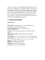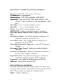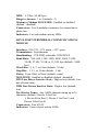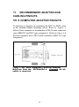
1
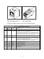
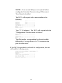
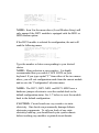
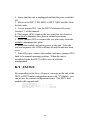
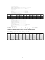
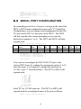
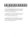
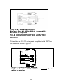
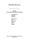
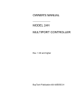
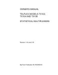
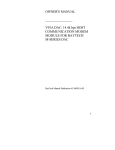
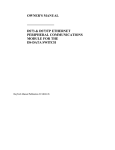
OWNER'S MANUAL
________________
DS SERIES
DATA SWITCH FOR
OUT-OF-BAND
MANAGEMENT
BayTech Manual Publication #U140A121-03
Thank you for selecting a DS Series Data Switch.
The data provided in this Owner's Manual explains the various
ways you can operate your DS unit and configure it to your
own computer system. We suggest that you read this manual
carefully before attempting to install the DS unit and that you
place special emphasis on correct cabling and configuration. If
you have any problems with your installation, please contact a
BayTech applications engineer for assistance.
BayTech manufactures many data acquisition and control
products, statistical multiplexers, printer sharing solutions and
network print servers. If you would like information on any of
these products, please contact BayTech customer service.
We welcome any comments you may have about our products.
And we hope that you will continue to look to BayTech for
your data communications needs.
2
NOTE: The information contained in this document is
subject to change without notice.
Copyright 1997 by Bay Technical Associates, Inc.
BayTech, Telplex, LaserShare, Print Master and TRAN-X
are registered trademarks of Bay Technical
Associates, Inc.
IBM, IBM PC, IBM PC/AT, IBM PC/XT are products and
registered trademarks of International Business
Machines Corporation.
Hewlett-Packard LaserJet is a product and registered
trademark of the Hewlett-Packard Company.
All products or company names are trademarks of their
respective holders.
3
TABLE OF CONTENTS
1.
GENERAL INFORMATION....................................................................6
2.
SPECIFICATIONS...................................................................................7
3.
3.1
3.2
3.3
3.4
4.
5.
CABLING..............................................................................................14
OPERATION.........................................................................................16
5.1
USER-PROGRAMMABLE-FEATURES..............................................16
5.1.1
SERIAL PORT CONFIGURATION..........................................16
5.1.2
PORT DEVICE NAME.............................................................18
5.1.3
PORT SELECT CODE .............................................................18
5.1.4
ATTENTION CHARACTER ...................................................18
5.1.5
DISCONNECT TIME GUARD ................................................20
5.1.6
CONNECT PORT ID ECHO ....................................................20
5.1.7
LOGIN SETUP .........................................................................20
5.1.8
LOCAL MODEM SETUP (FOR THE DS71 MD1 & DS71 MD2)21
5.1.9
DCD LOGON/LOGOFF (FOR THE DS71)................................21
5.2
BASIC OPERATION..........................................................................22
5.2.1
LOGIN PROCEDURE...............................................................24
5.3
PORT SELECTION PROCEDURE .....................................................26
5.3.1
ASCII STRING METHOD ........................................................26
5.3.2
MENU MODE--ATTENTION CHARACTER METHOD ........27
5.4
BINARY MODE.................................................................................29
5.5
BREAK CONDITION.........................................................................29
5.6
LED DESCRIPTION ..........................................................................30
5.7
DATA FLOW CONTROL ..................................................................30
5.8
I/O MODULES RESET .......................................................................34
5.9
UNIT RESET .....................................................................................34
6.
6.1
6.2
6.3
6.4
6.5
6.6
6.7
6.8
6.9
6.10
6.11
7.
INSTALLATION...................................................................................12
UNPACKING.....................................................................................12
SOFTWARE UTILITY DISKETTE...................................................12
POWER..............................................................................................13
GROUND............................................................................................13
CONFIGURATION................................................................................36
STATUS.............................................................................................40
SERIAL PORT CONFIGURATION....................................................42
PORT DEVICE NAME.......................................................................45
PORT SELECT CODE .......................................................................46
ATTENTION CHARACTER .............................................................46
DISCONNECT TIME GUARD ...........................................................47
CONNECT PORT ID ECHO ..............................................................47
LOGIN SETUP ...................................................................................48
DCD LOGON/LOGOFF(DS71)............................................................50
LOCAL MODEM SETUP(DS71 MD1 & DS71-MD2).....................50
EXIT ...............................................................................................52
MAINTENANCE ...................................................................................53
4
7.1
7.2
8.
RETURNS TO THE FACTORY .........................................................53
REPACKAGING FOR SHIPPING.......................................................53
TECHNICAL SUPPORT .......................................................................53
9.
FEDERAL COMMUNICATIONS COMMISSION RADIO FREQUENCY
INTERFACE STATEMENT*.............................................................................54
10.
FCC REQUIREMENTS FOR THE MD1 OR MD2 OPTIONAL MODEMS
55
11.
RECOMMENDED ADAPTER AND CABLING PINOUTS....................58
11.1
COMPUTER ADAPTER PINOUTS...............................................58
11.2
PRINTER/PLOTTER ADAPTER PINOUT ...................................59
11.3
MODEM ADAPTER PINOUT .......................................................60
11.4
RJ-45 CABLING PINOUT ..............................................................60
12.
DS71 EPROM UPGRADE DS71 EPROM UPGRADE............................61
13.
DS71-MD2 MECHANICAL LAYOUT ..................................................64
INDEX ................................................................................................................65
5
1. GENERAL INFORMATION
BayTech's DS Series Data Switch is a cost effective controller
designed for applications that require control of multiple
peripherals from a single host such as remote site management,
out-of-band management, general data switching, etc.. The DS
Series Data Switch can provide a full duplex connection
between the host and up to 32 local or remote peripherals. In a
typical application, the host port is connected to a local or
remote computer and the peripheral ports are connected to
devices such as routers, hubs, bar code readers, terminals, etc..
Port selection is accomplished two different ways. (1) Use a
simple menu-driven selection sequence or (2) send an ASCII
character string to select a port. The DS Series is compatible
with other BayTech products including the RPC Series remote
power strip.
The DS Series consists of a base unit, a DS71 host
communications module, DS74 4-port peripheral
communications modules or other peripheral communications
modules. The DS Series base unit has slide-in module
expansion slots and controls the display, non-volatile storage,
and data flow between connected modules. The data bus is an
internal matrix of high speed serial channels that allows
independent and simultaneous transmission of data between
modules.
The DS71 host communications module is a system data
controller that directs operations between the base unit, system
modules, and externally connected devices. The DS71
provides primary user access for systems communications. The
DS71 has a high speed EIA-232 port and two modem board
6
options for remote or local data acquisition and control. Users
can select a 14.4K bps, or a 2400 bps modem. The DS74 is a
4-port high speed EIA-232 peripheral communications module
that provides bi-directional communications between the host
device and a selected peripheral device connected to a DS74
port. The DS74 has selectable serial configuration for baud
rate, word size, stop bits, parity, DTR, RTS inactive state and
XON/XOFF handshaking for each port.
2. SPECIFICATIONS
BASE UNIT
I/O Modules: A maximum of 3, 6 or 9 modules can be
installed in the DS Series Data Switch.
Power Requirement: 115VAC/60Hz/0.3A or
230VAC/50Hz/0.2A.
Ground: Connect ground terminal on rear panel to earth
ground
Non-volatile Storage: 8KB holds power-up default
information.
Environment: 0° to 70°C temperature, 5% to 95% humidity.
Dimensions: DS 3: 16¾" w x 7_" d x 1 3/4" h, DS 6: 16¾"
w x 7_" d x 2 5/8" h, DS 9: 16¾" w x 7_" d x 3 1/2" h
Weight: DS Series: 4 lbs to 10 lbs
Indicators: 1 green power LED.
Mounting: Rack-mount or desktop.
Warranty: One year parts and labor.
7
8
DS71 HOST COMMUNICATIONS MODULE
Interface: EIA-232, -12V mark, +12V space
Transmission: Asynchronous
Handshaking: CTS/DTR; selectable XON/XOFF.
Baud Rate: 300, 600, 1200, 2400, 4800, 9600, 19.2K,
38.4K, 57.6K, 76.8K or 115.2K bps (default - 9600
bps)
Word Size: 5, 6, 7, or 8 bits (default - 8 bits)
Stop Bits: 1, 1½, or 2 bits (default - 1 bit)
Parity: Even, Odd, or None (default - none)
XON/XOFF: Enabled or disabled (default - disabled)
RTS Line Driver Inactive State: High or low (default high)
Port Device Name : Any ASCII character string up to 16
characters (default - Host EIA-232)
Port Select Code : Any ASCII character string up to 8
characters (default - $BT)
Menu Mode/Attention Character: Any ASCII character
(default ; )
Disconnect Time Guard: Enabled or disabled (default disabled)
Connect Port ID Echo: Disabled, Module/Port Number, or
Device Name (default - disabled)
Login Password: Any character string up to 8 characters,
enabled or disabled (default - BTA, disabled)
Connector: One eight pin modular connector (RJ-45).
Indicator: One red port-activity LED.
DS71 OPTIONAL MODEMS
The MD1 and MD2 modem boards attach to the DS71 host
communications module. The modem port has priority over the
EIA-232 port when contending for communications.
MD1: V.22bis (2400 bps)
9
MD2: V.32bis (14.4K bps)
Rings to Answer: 1 to 4 (default - 2)
Modem to Modem XON/XOFF: Enabled or disabled
(default - disabled)
Connectors: Two 4-modular connectors for connection to
phone line.
Indicators: Five red modem activity LEDs.
DS74 4-PORT PERIPHERAL COMMUNICATIONS
MODULE
Interface: EIA-232, -12V mark, +12V space
Transmission: Asynchronous
Handshaking: CTS/DTR; selectable XON/XOFF.
Baud Rate: 300, 600, 1200, 2400, 4800, 9600, 19.2K,
38.4K, 57.6K, 76.8K or 115.2K bps (default - 9600
bps)
Word Size: 5, 6, 7, or 8 bits (default - 8 bits)
Stop Bits: 1, 1½, or 2 bits (default - 1 bit)
Parity: Even, Odd, or None (default - none)
XON/XOFF: Enabled or disabled (default - disabled)
RTS Line Driver Inactive State: High or low (default - low,
not selected state)
DTR Line Driver Inactive State: High or low (default low)
Port Device Name : Any ASCII character string up to 16
characters (default - Device A for Port
1, Device B for Port 2, Device C for Port 3, and
Device D for Port 4)
Connectors: Four RJ-45.
Indicators: Four red port activity LEDs.
10
11
3. INSTALLATION
3.1 UNPACKING
After opening the box, check the packing list that comes with
the DS Series to ensure that you have received all components.
At a minimum you should have received the unit, this manual
with any applicable addendum, RJ-45 cable, adapters, and a
software utility diskette. The DS Series is provided with an
external AC power adapter. Check the unit to make certain
that it did not incur damage during shipping. If items are missing
or damage occurred, contact BayTech technical support at
800-523-2702.
3.2 SOFTWARE UTILITY DISKETTE
IMPORTANT: Copy the BayTech original diskette onto a
blank diskette and store the original in a safe place.
BayTech provides utility software for DOS compatible PCs to
assist you in configuring your DS Series unit. This diskette
contains the following programs: REMCONFG.COD,
SMODE.EXE, TERM.EXE and README.RDM. The DS
Series does not utilize the REMCONFG.COD file.
TERM.EXE is a terminal emulation program for DOS
compatible PCs used to configure the various features of the
unit. SMODE.EXE is a program used to configure COM ports
of DOS compatible machines to operate at speeds faster than
9600 bps.
Please review the README.RDM file to obtain instructions for
TERM.EXE and SMODE.EXE. To view the README.RDM
file on your screen, first insert the diskette into your PC's disk
12
drive and then enter the command TYPE README.RDM
from your disk drive prompt. To print this file, enter the
command COPY README LPT1: from your disk drive
prompt.
3.3 POWER
The DS Series requires external AC or DC power. Plug the
jack of the external power supply into the receptacle on the
back of the unit. Plug the AC connector into an AC outlet.
IMPORTANT: The AC outlet must be located near the
equipment and must be easily accessible.
The DS Series powers up when you press the power switch to
"1" (located on the rear panel). A green LED on the front panel
illuminates when power is applied.
CAUTION: Do not attempt to make any internal changes.
Any internal changes must be performed by an authorized
service technician or by BayTech. Please contact BayTech at
1-800-523-2702 for more information.
3.4 GROUND
The DS-Series Data Switch must be grounded to prevent
electrical shock hazard and to provide lightning protection. This
is accomplished by connecting the unit’s ground terminal, on the
rear panel, to earth ground. The earth ground connection
should be located as close as possible to the unit.
13
4. CABLING
The DS-Series Host Communications Modules have a RJ-45
connector for connection to a local EIA-232 device. The
DS71-MD1 and MD2 also have two RJ-11 connectors for
connection to a phone line. The DS74 has four RJ-45
connectors for connection to peripheral devices.
The cable required to connect either LINE port of the DS71MD1 or MD2 to the phone line is a standard RJ-11 straightthrough cable.
CAUTION: Use caution when installing or modifying
telephone lines. Never install telephone wiring during a lightning
storm. Never install telephone jacks in wet locations unless the
jack is specifically designed for wet locations. Never touch
uninsulated telephone wires or terminals unless the telephone
line has been disconnected at the network interface.
The DS71 and DS74 provide EIA-232 serial communications
on the RJ-45 port(s). Most serial computers, modems, and
printers do not have modular connectors. Adapters are
required to convert from DB-25 or DE-9 connectors to
modular connectors. BayTech has a complete line of modular
adapters and cables that make your installation quick and
trouble free. See Appendix A for recommended adapter and
cabling pinouts.
Figure 1 and Figure 2 are drawings of an RJ-45 receptacle
and plug. The pin number assignments are given.
14
Fig.1 RJ-45 Receptacle
Fig. 2 RJ-45 Plug
The DS71 and DS-74 RJ-45 ports use the following signals:
EIA-232 RJ-45 PIN/SIGNAL DEFINITION
Pin
EIA-232
Signal
Direction
Description
1
DTR
Output
DTR Line Driver Inactive State = High: +12V when powered
is applied, not used as a handshake line
DTR Line Driver Inactive State = Low : Handshake Out used
to enable/disable the receiving of characters when DS74 port
is selected, -12V when DS74 port is not selected.
2
GND
----
Signal Ground
3
RTS
Output
RTS Line Driver Inactive State = High: +12V when powered
is applied, not used as a handshake line
RTS Line Driver Inactive State = Low: +12V when DS74 port
is selected, -12V when DS74 port is not selected.
4
TX
Output
Transmit Data (data out)
5
RX
Input
Receive Data (data in)
6
DSR
Input
Handshake In, not used
7
GND
----
Signal Ground
8
CTS
Input
Handshake In, enable/disable the transmission of characters
15
5. OPERATION
5.1 USER-PROGRAMMABLE-FEATURES
User-programmable features for the DS71 and DS74 include
the Serial Port Configuration and Port Device Name. Other
programmable features for the DS71 include the Port Select
Code, Attention Character, Disconnect Time Guard, Connect
Port ID Echo, Login Setup, and Local Modem Setup or DCD
Logon/Logoff. These features are programmed by accessing
the menu-driven configuration mode from the DS71 (see
Section 6).
5.1.1 SERIAL PORT CONFIGURATION
You can program the Serial Port Configuration for the EIA-232
port on the DS71 module and all ports on the DS74 module.
The DS71 and DS74 modules translate data for devices using
different serial configurations. You can set the baud rate, word
size, stop bits, parity and XON/XOFF handshaking, RTS Line
Driver, and DTR Line Driver for each port. See Section 2
(Specifications) for a list of available serial parameters.
Factory default Serial Port Configuration is 9600 baud
rate, 8 bit word size, 1 stop bit, no parity, XON/XOFF
disabled, RTS Line Driver low on DS74 ports and high on
the DS71 port, and DTR Line Driver low. See Section 6
to reset a DS71, DS71-MD1 or DS71-MD2 to the default
configuration.
The I/O port’s RTS line will become active high when the port
is selected. It will return to an inactive state (programmable
when the port is de-selected).
16
17
5.1.2
PORT DEVICE NAME
The DS71 and DS74 Port Device Name is used for
identification purposes while in configuration mode. The DS74
Port Device Name can be used in conjunction with DS71
Connect Port ID Echo feature (see Section 5.1.6) to send a
message to the host terminal when a DS74 port is selected for
communications. The Port Device Name can be programmed
to be any ASCII character string up to sixteen characters. The
default Port Device Name is Host EIA-232.
5.1.3 PORT SELECT CODE
The Port Select Code is a programmable ASCII character
string that can range from 1 to 8 characters. The Port Select
Code is sent as part of a select sequence by the host terminal to
the DS71 to access configuration mode or select specific DS74
ports. Section 5.3 describes how the Port Select Code is used
to select specific DS74 ports and Section 6 describes how the
Port Select Code is used to access configuration mode. The
default Port Select Code is $BT.
5.1.4 ATTENTION CHARACTER
The Attention Character is sent in sequence by a user
connected to the DS71 to invoke a port selection menu. The
port selection menu allows the user to select specific DS74
ports for communication or access configuration mode for the
DS71. The default Attention Code is ; (semicolon).
18
19
5.1.5
DISCONNECT TIME GUARD
Disconnect Time Guard is used to prevent unwanted
disconnections to selected port if the attention characters are
sent in the data stream. The Disconnect Time Guard feature
operates with the “Attention Character” method, it is not a
feature of the “Port Select Code” method of operation.
Disconnect Time Guard can be enabled or disabled. The
default Disconnect Time Guard is disabled.
5.1.6 CONNECT PORT ID ECHO
Connect Port ID Echo is used to send a message to the host
terminal when a DS74 port is selected. The Connect Port ID
Echo can be programmed to be the module number and port
number of the selected DS74 port, the Port Device Name of
the selected DS74 port, or disabled.
The default Connect Port ID Echo is disabled.
5.1.7 LOGIN SETUP
The Login Setup offers four(4) user configuration options.
(1) The login Header message can be enabled or disabled on
the DS71-MD1 or DS71-MD2. The initial header message
appears only on DS71 Host modules with built-in modems.
The header message looks similar to the following:
Data Switch Series--Bay Technical Associates
Port Select Code: $BT
Attention Character : ;
The header message is enabled by default.
20
(2) The Password status is used for security purposes. When
enabled, a user connected to the DS71 must send the
programmed password at the login prompt to access any
functions of the DS Series. The Login Password can be
disabled so a login procedure is not required to access the DS
Series. The default login password is BTA and disabled.
(3) The DS-Series login setup selection Menu can be enabled
or disabled. When the “Auto Connect” is enabled, it will
disable the menu selection screen from appearing at the initial
login. The login setup selection menu is disabled by default.
(4) The Auto Connect feature allows users to select the DS74 module and port that will be connected on initial power up.
This feature can be enabled or disabled. When the “Auto
Connect” is enabled, it will disable the menu selection screen
from appearing at the initial login. The Auto Connect selection
is disabled by default.
5.1.8 LOCAL MODEM SETUP (FOR THE
DS71 MD1 & DS71 MD2)
You can program the Number of Rings to Answer from 1 to 4
rings and enable or disable Modem to Modem XON/XOFF
handshaking for units with the MD1 or MD2 modem options
installed. The default Number of Rings to Answer is 2 and
Modem to Modem XON/XOFF handshaking is disabled
by default.
5.1.9 DCD LOGON/LOGOFF (FOR THE
DS71)
The DCD Logon/Logoff feature is enabled by default. It should
remain disabled for applications where a computer will be
connected directly to the DS71. The DCD
21
LOGON/LOGOFF feature should be enabled in applications
where you are using an external modem with the DS71 Host
Module. When enabled and an external modem is used, you
can not continue into the logon procedures and normal
operations until the DCD line is high. If the DS-Series is in
normal operation and the DCD line goes low(the modem lost
connection), the DS71 will return to Logoff state and you can
not continue operation until the modem is back on line and the
DCD line is high.
The Logon/Logoff feature is both a menu selectable item and
also a hardware jumper selectable change made on the DS71's
PC board. See the Mechanical Layout Section 13 of this
manual. To use the DCD Logon feature, the jumper next to the
RJ-45 connector on the DS71, JP6-pin2 must be connected to
JP6-pin1 (move the jumper toward the module cover plate).
JP5 should not be moved.
5.2 BASIC OPERATION
When a local terminal or PC is connected to the DS Series
Data Switch or when a remote PC has established a connection
with an external or internal modem(DS71 MD1 or MD2), you
are ready to perform commands. If you are using a PC, you
can communicate with the unit by using a terminal emulation
program or by using a software communications program that
emulates a terminal.
BayTech supplies an utility diskette which includes TERM.EXE,
a terminal emulation program, to put your PC into terminal
emulation mode(see section 3.2). Popular communication
software packages, such as PROCOMM PLUS by DataStorm
22
Technologies, also provide terminal emulation capabilities and
allow for communications with the DS Series Data Switch.
23
When all the equipment has been connected to the DS Series
and the DS Series has been configured for the desired
parameters, the user connected to the DS71 host module is
ready to perform data communications with the equipment
connected to the DS74 peripheral module(s). DS Series
configuration is menu-driven and is discussed in Section 6.
Data communications involves logging into the DS Series
operations mode (if Login Password is enabled) and selecting
the desired DS74 port. Once a DS74 port is selected, full
duplex communication is established between the host user and
the selected port. Section 5.2.1 describes the login procedure
and Section 5.3 describes port selection methods. To invoke a
port selection menu using the Menu mode or attention character
method send five ;;;;; (default).
IMPORTANT: The MD1 or MD2 modem option has
priority over the EIA-232 port. If a local user connected to the
EIA-232 port is currently logged in, while in configuration
mode, or connected to a DS74 port and a remote user dials
into the DS71 modem, the local user will be "booted" off to
allow the remote user to communicate with the DS unit.
IMPORTANT: If you have the MD1 option (2400 bps
modem), you must configure your modem for a fixed rate of
2400 bps (i.e., send ATF5<cr>).
5.2.1 LOGIN PROCEDURE
The DS Series comes from the factory with the Login Password
disabled. If you enable the Login Password, you will need to
perform the correct login sequence. If you have a terminal
connected to the EIA-232 port and the DS Series is powered
24
on or you dial into DS Series internal modem (if installed), you
will receive the following message:
25
Data Switch Series - F.1.07
Bay Technical Associates
To login, enter password
Login:
Type the programmed password (default is BTA) followed by
<ENTER>. The DS71 will echo back asterisk characters (*)
for each character typed at this prompt. When you type the
correct password and <ENTER>, the DS71 will respond with:
Login successful
Port Select Code: $BT
Attention Character: ;
At this point, you can select a specific DS74 port as described
in Section 5.2.2, access configuration mode as described in
Section 6, or logout.
Logout is accomplished by sending a “T” (in Menu mode or
attention character method). Once you logout, the DS71 will
respond with:
Logout successful
Data Switch Series - F.1.07
Bay Technical Associates
To login, enter password
Login:
5.3 PORT SELECTION PROCEDURE
There are two methods to select a DS74 port. You can either
send a port selection sequence which consists of an ASCII
character string or send the Attention Character five
times(default ;;;;;) to invoke a port selection menu.
IMPORTANT: If the ASCII String Method is used to select
a DS74 port, the ASCII String Method must be used for port
disconnection. If the Menu mode or attention character method
is used to select a DS74 port, the Menu mode or attention
character method must be used for port disconnection.
5.3.1 ASCII STRING METHOD
26
A DS74 port can be selected by sending an ASCII character
string to the DS71 host module that consists of the Port Select
Code (default is $BT), the desired DS74 module number (2 to
3 for DS3), (2 to 6 for DS6), and (2 to 9 for DS9), the desired
DS74 port number (1 to 4), and either Carriage Return (0D
Hex) or Line Feed (0A Hex).
For example, to select Port 1 of a DS74 module installed as
Module 2 using the default Port Select Code, send
$BT2,1<cr> or $BT2,1<lf> where <cr> is Carriage Return,
and <lf> is Line Feed.
To disconnect, either select another DS74 port or send the
disconnect sequence. The disconnect sequence consists of the
Port Select Code followed by Carriage Return or Line Feed
(e.g., $BT<cr>). Once you disconnect, you can logout by
typing LOGOUT<cr>.
5.3.2 MENU MODE--ATTENTION
CHARACTER METHOD
A DS74 port can also be selected by invoking a port selection
menu. The port selection menu is invoked by sending the
Attention Character (default is ;;;;;) to the DS71 host module
five times followed by a one second delay. If Disconnect Time
Guard is enabled, a delay is required before and after the
Attention Characters are sent (delay>;;;;;<delay>). In both
cases the DS71 will respond with a menu similar to the
following, if a single DS74 module is installed as Module 2:
27
Device A
(2,1)............1
Device B
(2,2)............2
Device C
(2,3)............3
Device D
(2,4)............4
Configure.........................C
I/O Modules Reset.................RM
Unit Reset........................RU
Exit..............................X
Logout............................T
Enter Request :
The names in the left column are the same as programmed for
the DS74 Port Device Names and the (m,n) numbers in the
middle correspond to the DS74 module, port. Type the
number corresponding to the desired DS74 port to select that
port followed by <ENTER>. Type "C" to receive the
"Configuration" selection menu (see Section 6), "X" to Exit, or
"T" to logout.
Once a port is selected, you can select another port by sending
the Attention character five times followed by a one second
delay to invoke the port selection menu. If the Disconnect Time
Guard is disabled, you can also select another port on the same
module by sending the Attention Character five times, the
appropriate port number with no delay after the Attention
Characters and then a Carriage Return.
NOTE: The disconnect Time Guard feature is available to
prevent erroneous disconnections to selected ports. The
Disconnect Time Guard, when enabled, required a delay before
and after the Attention Characters to select a different port.
If you type "X" from the port selection menu to exit, the DS71
will return to the mode where it is awaiting an ASCII command
or the Attention Code to be sent five times. If you type "T" to
logout, the DS71 will respond with the following if Login
Password is enabled:
28
Logout successful
Data Switch Series - F.1.07
Bay Technical Associates
To login, enter password
Login:
5.4 BINARY MODE
Binary mode allows you to pass the Port Select Code and/or
Attention Character through to a device connected to a DS74
port. Binary mode is useful when sending binary data that might
contain the Port Select Code. Binary mode is effective only
when using the ASCII String Method to select ports.
Binary mode is accessed using the ASCII String Method by
sending the Port Select Code, capital B, and Carriage Return
after a DS74 port has been selected. For example, if using the
default Port Select Code ($BT), Module 2 Port 1 can be
placed into binary mode by sending $BT2,1<cr>$BTB<cr>.
While operating in binary mode, you will be unable to select
another port or access configuration mode until you terminate
binary mode. Binary mode is terminated by sending a BREAK
condition.
5.5 BREAK CONDITION
The DS-Series host module will pass a “BREAK” condition
through to any selected peripheral port, provided that you are
not operating in binary mode. Binary mode is terminated by
sending a “BREAK” condition. The BREAK condition
commands can be sent using many popular communications
software packages. (Examples: Mirror--Esc SB<cr>,
ProComm--Alt B).
29
5.6 LED DESCRIPTION
A DS71 ordered without a modem option comes with a single
LED on the module. This LED illuminates whenever the DS71
is ready for operation. A DS71 ordered with an MD1 or MD2
modem option comes with five modem activity LEDs. These
LEDs are marked as TD, RD, CD, MR, and CX. These LEDs
are described below.
TD (Transmit Data): Indicates the modem is
transmitting data.
RD (Receive Data): The modem is receiving data.
CD (Carrier Detect): Indicates that a valid carrier
has been detected.
MR (Modem Ready): Indicates the modem is ready
to communicate.
CX (Connection): Indicates the DS71 has a
connection to a DS74 module or port.
The DS74 has four LEDs labeled as CX1, CX2, CX3, and
CX4. When the DS71 host module establishes a connection
with a DS74 port, the CXn LED will illuminate (n = 1 to 4).
5.7 DATA FLOW CONTROL
NOTE: When XON/XOFF is enabled, the DS Series will
continue to support hardware handshaking lines. If this is not
desired, you may disconnect the handshaking lines entirely.
Once a connection is established and the host device transmits
data to the DS71, the data is received and stored in a
250-character transmit buffer which in turn retransmits the data
to the selected peripheral device. When the buffer receives 120
30
characters, the DS Series will make the host port DTR line false
(negative voltage) and send an XOFF character (if
XON/XOFF handshaking is enabled in the DS71 receive
direction), signaling the host device that it cannot accept more
data. When the buffer empties, the DS71 will make the DTR
line true (positive voltage) and send an XON character (if
XON/XOFF is enabled), signaling the host device that it can
accept more data. When the DS71 transmits data to the host
device and the host device cannot receive data, the DS71 will
expect to see a false condition on the CTS line or receive an
XOFF character (if XON/XOFF is enabled in the DS71
transmit direction). When the host device is able to receive
more data, the DS74 will expect to see a true condition on the
CTS line or receive an XON character (if XON/XOFF is
enabled).
When a peripheral device transmits data to a DS74 port that is
selected by the DS71 host module, the data is stored in a
1024-character receive buffer. When the buffer receives 820
characters, the DS74 will make the peripheral port's DTR line
false (negative voltage) and send an XOFF character (if
XON/XOFF is enabled in the DS74 port's receive direction),
signaling the peripheral device that it cannot accept data. When
the buffer empties, the DS74 will make the CTS line true
(positive voltage) and send an XON character (if XON/XOFF
is enabled), signaling the peripheral device that it can accept
more data. When the DS74 transmits data to the selected
peripheral device and the peripheral device cannot receive data,
the DS74 will expect to see a false condition on the CTS line or
receive an XOFF character (if XON/XOFF is enabled in the
31
DS74 transmit direction). When the peripheral device can
receive more data, the DS74 will expect to see a true condition
on the CTS line or receive an XON character (if XON/XOFF
is enabled).
NOTE: The DS74 ports do not have any buffering capability
to receive data when not selected by the DS71. The DS74
ports can be programmed to do hardware flow control on
either the RTS (Ready To Send) line or DTR. In addition, the
DS74 ports can be programmed to do XON/XOFF flow
control.
If the DS74 port's RTS or DTR Line Driver Inactive State is
programmed to be low (default - see Section 6.2), the RTS
and/or DTR line will be false (negative voltage) when the DS74
port is not selected. The DS74 port's RTS and/or DTR line will
be set to true (positive voltage) when selected by the host
device. The DTR line is used as an active handshake line.
If the DS74 port's RTS or DTR Line Driver Inactive State is
programmed to be high, the RTS and/or DTR line will be high
all the time.
If the DS74 port's is programmed for XON/XOFF
handshaking (see Section 6.2), an XOFF character is sent
when the DS74 port is not selected signaling the attached
peripheral device that it cannot accept data. The DS74 port
will send an XON character when selected by the host device
signaling the attached peripheral device that it can now accept
data.
The I/O port’s RTS line will become active high when the port
is selected. It will return to an inactive state (programmable
when the port is de-selected).
32
33
5.8 I/O MODULES RESET
The I/O Modules can be reset if you determine that connected
equipment is “hung-up”. The I/O Modules Reset menu
selection is found in the Port Selection Menu. The Port
Selection Menu is invoked by sending the Attention
Character(default ;;;;;) to the DS71 host module five times. The
DS71 will respond with a menu similar to the following, if a
single DS74 modules is installed as Module 2.
By responding to the Enter Request: message at the end of the
menu with RM , you will reset all of the I/O Modules.
Device A
(2,1)............1
Device B
(2,2)............2
Device C
(2,3)............3
Device D
(2,4)............4
Configure.........................C
I/O Modules Reset.................RM
Unit Reset........................RU
Exit..............................X
Logout............................T
Enter Request :RM
I/O Modules Reset Successfully
Strike any Key to Continue
5.9 UNIT RESET
There are two methods used to instruct the entire DS-Series
system to “reset”. There is (A) the Character String method or
(B) the Unit Reset menu selection method to reset the unit.
Only a user connected to the host module can issue the reset
commands. These commands do not affect any saved
configuration parameters that have been changed from the
default values.
Important: Both of the Unit Reset commands will terminate
communications with either an internal or external modem
connected to the DS71. You must redial to re-establish
communications with the DS-Series system after the unit has
been reset.
34
(A). The Character String method to reset the DS-Series unit
utilizes the following format:
BAYTECHRESET<cr>
(B). The Unit Reset menu selection is found in the Port
Selection Menu. The Port Selection Menu is invoked by
sending the Attention Character(default ;;;;;) to the DS71 host
module five times. The DS71 will respond with a menu similar
to the following, if a single DS74 modules is installed as Module
2.
By responding to the Enter Request: message at the end of the
menu with RU, you will reset the DS-Series unit.
Device A
(2,1)............1
Device B
(2,2)............2
Device C
(2,3)............3
Device D
(2,4)............4
Configure.........................C
I/O Modules Reset.................RM
Unit Reset........................RU
Exit..............................X
Logout............................T
Enter Request :RU
Data Switch Series
Bay Technical Associates
Port Select Code: $BT
Attention Character: ;
The DS-Series unit has been reset.
35
6. CONFIGURATION
Configuration changes for the DS Series are made through the
DS71 host module. Use the following procedure to access
configuration mode for the DS Series:
1.
Connect a terminal to the DS71 EIA-232 port with the
appropriate cable or establish a connection with the
DS71 internal modem (if installed). If configuring from
the EIA-232 port, configure the host terminal's serial
parameters to match those of the DS71. From the
factory, the DS71 is set at 9600 baud, 8 data bits, 1
stop bit, no parity, and XON/XOFF disabled. If you
do not have a dumb terminal or terminal emulation
software, BayTech supplies a utility diskette which
includes software to put an IBM PC or compatible into
terminal mode (TERM.EXE).
IMPORTANT: The MD1 or MD2 modem option
has priority over the EIA-232 port. If a local user
connected to the EIA-232 port is currently logged in, in
configuration mode, or connected to a DS74 port and a
remote user dials into the DS71 modem, the local user
will be "booted" off to allow the remote user to
communicate with the DS unit.
2.
When the DS Series is powered up or when a
connection is established to the DS71 optional internal
modem, the DS Series will send a message similar to
the following if Login Password is enabled:
Data Switch Series - F.1.07
Bay Technical Associates
36
To login, enter password
Login:
Type the appropriate password (default is BTA). The
DS Series will respond with:
Login successful
Port Select Code: $BT
Attention Character: ;
3.
There are two methods to access configuration mode
for either the DS71 host module or a DS74 peripheral
module. You can either send two ASCII strings or
invoke the port selection menu by sending the Attention
Character five times.
ASCII STRING METHOD
If using the ASCII string method, the first string to send
is the Port Select Code (default -$BT), the desired
module number (1 to 6), and Carriage Return or Line
Feed. The second string to send is $CONFIG
followed by Carriage Return or Line Feed. There
should be a one second pause between the first string
and the second string. For example, to access
configure mode for a DS74 peripheral module installed
as Module 2, send
$BT2<cr><delay>$CONFIG<cr> where <cr> is
Carriage Return and <delay> is a one second delay.
No characters should be sent between $BT2<cr> and
$CONFIG<cr>.
MENU MODE/ATTENTION CHARACTER
METHOD
To invoke the port selection menu, send the Attention
Character (default - ;) five times preceded and followed
by a one second delay (e.g., <delay>;;;;;<delay>).
37
NOTE: A one second delay is not required before
sending the Attention Character string if Disconnect
Time Guard is disabled.
The DS71 will respond with a menu similar to the
following:
Device A
(2,1)............1
Device B
(2,2)............2
Device C
(2,3)............3
Device D
(2,4)............4
Configure.........................C
I/O Modules Reset.................RM
Unit Reset........................RU
Exit..............................X
Logout............................T
Enter Request :
Type "C" (Configure). The DS71 will respond with the
"Configuration" selection menu as follows:
Configuration
Module 1..........................1
Module 2..........................2
Select Port.......................S
Exit..............................X
Enter Request :
Type the number corresponding the desired module
followed by Carriage Return or "S" to return to the
port selection menu.
If the DS71 host module is selected for configuration, the unit
will send the following menu:
Copyright(C) Bay Technical Associates 1997
DS-71 Data Switch Series - Host Module
Revision F.1.07
Module 1
Status.............................1
Serial Port Configuration..........2
Port Device Name...................3
Port Select Code...................4
Attention Character................5
38
Disconnect Time Guard..............6
Connect Port ID Echo...............7
Login Setup........................8
DCD Logon/Logoff...................9 (DS71)
or Local Modem Setup...............9 (MD1 & MD2)
Configure Another Module...........C
Exit...............................X,<CR>
Enter Request :
NOTE: Item 9 in the menu above (Local Modem Setup) will
only appear if the DS71 module is equipped with the MD1 or
MD2 modem option.
If the DS74 module is selected for configuration, the unit will
send the following menu:
Copyright(C) Bay Technical Associates 1997
Data Switch Series - EIA-232 I/O Module
Module 2
Status.............................1
Serial Port Configuration..........2
Port Device Name...................3
Configure Another Module...........C
Exit...............................X,<CR>
Enter Request :
Type the number or letter corresponding to your desired
choice.
NOTE: Menu selection is case sensitive. It is highly
recommended that you enable CAPS LOCK on your
keyboard. If you type capital "C" from either of the two menus
above, you will exit configuration mode from the current module
and receive the "Configuration" selection menu.
NOTE: The DS71, DS71-MD1 and DS71-MD2 have a
hardware jumper selection to reset the module back to the
default configuration status. See 1-7 below to reset the module
back to the default configuration:
CAUTION: Circuit boards are very sensitive to static
electricity. One shock can permanently damage delicate
electronic components. To rid your body of any static
electricity build-up, you should touch your system chassis
before touching any modules or printed circuit boards.
39
1. Insure that the unit is unplugged and that the power switch is
off.
2. Remove the DS71, DS-MD1 or DS71-MD2 module from
the base unit.
3. Locate jumper JP4. See the DS71 Mechanical Layout,
Section 13, of this manual.
4. The jumper (JP4) connects the two pins that are closest to
the module’s aluminum face plate in normal operations.
5. Move jumper (JP4) to connect the two pins away from the
module’s aluminum face plate.
6. Install the module and return power to the unit. After the
self test sequence, the LEDs will turn off and the unit has been
reset.
7. Turn off power, remove the module and move jumper (JP4)
back to its normal operating position. When the unit is
assembled again the DS71 will be set to it’s default
configuration.
6.1 STATUS
By responding to the Enter Request: message at the end of the
DS71 or DS74 main configuration menu with "1" (Status), you
can review the current configuration status. The DS71 host
module will respond with:
Installed Modules :1,2
Port Select Code is................$BT
Attention Character is.............;
Disconnect Time Guard is...........Disabled
Port ID Echo is....................Disabled
40
Local Modem Setup :
Rings to Auto-Answer...............2
Modem to Modem Xon/Xoff Flow Control is ..Disabled
Modem Connectivity Time-out is......Disabled
Escape Character is................43(+)
Login Setup:
Header is..........................Enabled
Password is........................Disabled
Menu is............................Disabled
Auto Connect Port is...............Module 2,Port 1
Auto Connect.......................Disabled
Strike any Key to Continue
Port
1
2
Device
Name
Host EIA-232
Host Modem
Baud
Rate
9600
57.6k
Word
Size
8
8
Stop
Bits
1
1
Parity
None
None
Xon/
Xmit
Off
Off
Xoff/
Recv
Off
Off
Line
DTR
High
High
Drive
RTS
High
High
Strike any Key to Continue
Status.............................1
Serial Port Configuration..........2
Port Device Name...................3
Port Select Code...................4
Attention Character................5
Disconnect Timeguard...............6
Connect Port ID Echo...............7
Login Setup........................8
DCD Logon/Logoff...................9 (DS71)
or Local Modem Setup...............9 (MD1 & MD2)
Configure Another Module...........C
Exit...............................X,CR
Enter Request :
NOTE: Port 2 in the menu above will only appear if the DS71
module is equipped with the MD1 or MD2 modem option.
The DS74 peripheral module will respond with:
Port
1
2
1
2
Device
Name
Device A
Device B
Device C
Device B
Baud
Rate
9600
9600
9600
9600
Word
Size
8
8
8
8
Stop
Bits
1
1
1
1
Strike any Key to Continue
41
Parity
None
None
None
None
Xon/
Xmit
Off
Off
Off
Off
Xoff/
Recv
Off
Off
Off
Off
Line
DTR
Low
Low
Low
Low
Drive
RTS
Low
Low
Low
Low
Status.............................1
Serial Port Configuration..........2
Port Device Name...................3
Configure Another Module...........C
Exit...............................X,CR
Enter Request :
6.2 SERIAL PORT CONFIGURATION
By responding to the Enter Request: message at the end of the
DS71 or DS74 main configuration menu with "2" (Serial Port
Configuration), you can change serial configuration for the EIA232 port on the DS71 or any port on the DS74. The DS74
will first respond with a menu prompting you to enter the
desired port number (1 to 4). The DS71 and DS74 will then
respond with:
Module 2 Serial Port Configuration :
Port
1
2
Device
Name
Host EIA-232
Host Modem
Baud
Rate
9600
57.6k
Exit/Save......1
Set Baud Rate..2
Set Word Size..3
Set Stop Bits..4
Set
Set
RTS
DTR
Word
Size
8
8
Stop
Bits
1
1
Parity
None
None
Xon/
Xmit
Off
Off
Xoff/
Recv
Off
Off
Parity........5
Xon/Xoff......6
Line Driver...7
Line Driver...8
Enter Request :
You can now reconfigure the DS71 EIA-232 port or the
selected DS74 port by sending the appropriate option (1 to 8)
from the menu. For example, to change the baud rate to
115.2K, send "2" (Set Baud Rate). The DS71 or DS74 will
respond with:
1
2
3
4
5
6
7
8
9
A
B
Enter
For
300
For
600
For 1200
For 2400
For 4800
For 9600
For 19200
For 38400
For 57.6K
For 76.8K
For 115.2K
Request :
Send "B" for 115.2K baud rate. The DS71 or DS74 will
respond with the reconfigured status of the port as follows:
Module 2 Serial Port Configuration :
42
Line
DTR
High
High
Drive
RTS
High
High
Port
1
Device
Name
Device A
Baud
Rate
9600
Exit/Save......1
Set Baud Rate..2
Set Word Size..3
Set Stop Bits..4
Enter Request :
Word
Size
8
Set
Set
RTS
DTR
Stop
Bits
1
Parity
None
Xon/
Xmit
Off
Xoff/
Recv
Off
Line
DTR
Low
Parity........5
Xon/Xoff......6
Line Driver...7
Line Driver...8
You can now select other options from the menu. For example,
to enable Xon/Xoff handshaking in the receive data direction
only, send "6" (Set Xon/Xoff Xmit) in response to the prompt.
The DS71 or DS74 will respond with:
Output Flow Control (Xmit) - Xon/Xoff is ( OFF )
Stop/Restart Output Upon Receiving of Xoff/Xon ?
(Y/N) :
You should enter "Y" to enable XON/XOFF on transmit or "N"
to disable XON/XOFF on transmit. Following our example,
enter "N" and the module will respond with:
Input Flow Control (Recv) - Xon/Xoff is ( Off )
Xoff/Xon sent based on Buffer - Full/Empty condition ? (Y/N) :
You should enter "Y" to enable XON/XOFF on receive or "N"
to disable XON/XOFF on receive. Following our example,
enter "Y" and the module will respond with the reconfigured
status for the selected port as follows:
43
Drive
RTS
Low
Module 2 Serial Port Configuration :
Port
1
Device
Name
Device A
Baud
Rate
9600
Exit/Save......1
Set Baud Rate..2
Set Word Size..3
Set Stop Bits..4
Word
Size
8
Set
Set
RTS
DTR
Stop
Bits
1
Parity
None
Xon/
Xmit
Off
Xoff/
Recv
Off
Line
DTR
Low
Parity........5
Xon/Xoff......6
Line Driver...7
Line Driver...8
Enter Request :
If there are no other changes, send "1" (Exit/Save) and the
DS71 or DS74 will respond with:
Save Changes Permanently ? (Y/N) :
If you type "Y", the new configuration for the selected port is
stored permanently in non-volatile memory and the module will
subsequently power up at the new configuration. If you type
"N", the new configuration is stored in RAM and lost once
power is removed from the unit. The DS71 or DS74 will return
to the main configuration menu.
NOTE: If you are configuring the DS71 from the EIA-232
port, the DS71 will respond with:
Change Device to NEW Configuration
Before Answering This Request.
CAUTION: This message reminds you to change the serial
port configuration of the host device to match the new
configuration of the host port. If they do not match, the DS71
will be unable to interpret the next command and you will be
unable to access any multiport function. If this happens, cycle
power on the multiport and reconfigure the unit. Make any
necessary changes to the host device before answering the
"Save Changes Permanently?" prompt.
44
Drive
RTS
Low
6.3 PORT DEVICE NAME
By responding to the Enter Request: message at the end of the
DS71 or DS74 main configuration menu with "3" (Port Device
Name), you can change the Port Device Name. The DS74
module will first prompt you to enter the desired number (1 to
4) followed by <ENTER>. The DS71 and DS74 modules will
respond with a menu similar to the following:
Module 1 Device Name :
Port
1
Device
Name
Device D
Baud
Rate
9600
Word
Size
8
Stop
Bits
1
Parity
None
Xon/
Xmit
Off
Xoff/
Recv
Off
Line
DTR
High
Drive
RTS
High
Enter Port Device Name (Max. 16 characters):
or ENTER for no change ...........:
Enter the desired Port Device Name up to 16 characters. For
example, if you type "PORT 4" followed by <ENTER>, the
module will respond with:
Module 1 Device Name :
Port
1
Device
Name
Port 4
Baud
Rate
9600
Word
Size
8
Stop
Bits
1
Parity
None
Xon/
Xmit
Off
Xoff/
Recv
Off
Enter Port Device Name (Max. 16 characters):
or ENTER for no change ...........:
If the Port Device Name is satisfactory, type <ENTER>. The
DS71 or DS74 will return to the main configuration menu.
NOTE: If the DS71 Connect Port ID Echo feature is
programmed for Use Device Name (see Section 6.6), the
message sent to the host device when the host selects a DS74
peripheral port will be the Device Name shown in the menu
above.
45
Line
DTR
High
Drive
RTS
High
6.4 PORT SELECT CODE
By responding to the Enter Request: message at the end of the
DS71 main configuration menu with "4" (Port Select Code),
you can change the Port Select Code to any ASCII character
string from 1 to 8 characters. The DS71 will respond with:
Port Select Code is................$BT
Change It ? (Y/N) :
Type "Y" to change the Port Select Code. The DS71 will
respond with:
Enter Port Select Code (Max. 8 characters):
Type the desired Port Select Code followed by <ENTER>.
For example, if you type #PORT followed by <ENTER>, the
DS71 will respond with:
Port Select Code is................#PORT
Change It ? (Y/N) :
If no additional change is desired, type "N". The DS71 will
store the new Port Select Code permanently into non-volatile
memory and return to the main configuration menu.
6.5 ATTENTION CHARACTER
By responding to the Enter Request: message at the end of the
DS71 main configuration menu with "5" (Attention Character),
you can change the Attention Character to be any ASCII
character. The DS71 will respond with:
Attention Character is............ ;
Change It ? (Y/N) :
Type "Y" to change the Attention Character. The DS71 will
respond with:
Enter Attention Character :
46
Type the desired Attention Character. For example, if you type
"%", the DS71 will respond with:
Attention Character is............ %
Change It ? (Y/N) :
Type "N" if no additional change is desired. The DS71 will
store the new Attention Character into non-volatile memory and
return to the main configuration menu.
6.6 DISCONNECT TIME GUARD
By responding to the Enter Request: message at the end of the
DS71 main configuration menu with "6" (Disconnect Time
Guard), you can determine if you want a one second delay is
required when using the Menu mode or attention character
method to select ports or disconnect as discussed in Section
5.3.2. The DS71 will respond with:
Disconnect Time Guard is..................Enabled
Enable ? (Y/N, CR for no change):N
Type "Y", to toggle the existing state of Disconnect Time Guard
or "N" for no change. The DS71 will store the selected state of
the Disconnect Time Guard into non-volatile memory and return
to the main configuration menu.
Note: The Disconnect Time Guard operates with the
“Attention Character” method, it is not a feature of the “Port
Select Code” method of operation.
6.7 CONNECT PORT ID ECHO
By responding to the Enter Request: message at the end of the
DS71 main configuration menu with "7" (Connect Port ID
Echo), you can change the message sent to the host device
when a DS74 peripheral port is selected. The DS71 will
respond with:
47
Port ID Echo is....................Disabled
Change It ? (Y/N) :
Type "Y" to change the Connect Port ID Echo. The DS71 will
respond with:
Disable Port ID Echo..............1
Use Module,Port number............2
Use Device Name...................3
Exit..............................X,CR
Enter Request :
Enter the number corresponding to your desired choice. The
DS71 will store the selected Connect Port ID Echo into nonvolatile memory and return to the main configuration menu.
NOTE: If you type "3" (Use Device Name), the programmed
Port Device Name for the selected DS74 port will be sent to
the host device (see Section 6.3).
6.8 LOGIN SETUP
By responding to the Enter Request: message of the DS71
main configuration menu with "8" (Login Setup), you can change
the Header, Login Password, Menu and Auto Connect Status.
The DS71 will respond with:
Header............................1
Password..........................2
Menu..............................3
Auto Connect......................4
Exit..............................X,CR
Type "1" to enable or disable the modems(MD1 or MD2) initial
header message. The modem will respond with:
Header is.........................Disabled
Enable ? (Y/N, CR for no change):
Type "2" to change the Password. The DS71 will respond
with:
48
Change Password.....................1
Enabled/Disabled....................2
Exit................................X,CR
Type “1” to enter the new password up to 8 ASCII characters
followed by <ENTER>. Type “2” to disable the Login
Password. For example, if you what to change the Login
Password to LOGIN, type "LOGIN" at the prompt. The
DS71 will respond with:
Enter New Password( 1 - 8 char., CR to end):
If the Login Password is correct, type "N". The DS71 will
store the new Login Password into non-volatile memory and
return to the main configuration menu.
Type "3" to enable or disable the login selection Menu. Login
Password. The DS71 will respond with:
Menu is............................Disabled
Enable ? (Y/N, CR for no change):
Type "4" to change the auto connect port. The auto connect
port feature allows users to selected the DS-74 module and
port that will be automatically connected on power up. The
auto connect port has priority over the login setup menu
enable/disable selection. The DS71 will respond with:
Auto Connect Port is..............Module 3, Port 2
Auto Connect is ..................Enabled
Change Auto Connect Port .........1
Enabled/Disabled..................2
Exit..............................X,CR
Note: When “Auto Connect” is enabled, it will disable the
menu selection screen from appearing at the initial login
sequence.
49
6.9
DCD LOGON/LOGOFF(DS71)
NOTE: This section applies to the DS71 host module without
the modem option installed.
By responding to the Enter Request: message at the end of the
DS71 main configuration menu with "9" (DCD Logon/Logoff),
you can change the DCD Logon/Logoff mode. The DS71 will
respond with:
Enter Request : 9
DCD Logon/Logoff mode is.................Disabled
Enable ? (Y/N, CR for no change) :
The Logon/Logoff feature is both a menu selectable item and a
hardware jumper selectable change made on the DS71's PC
board. See the Mechanical of this manual. To
enable the DCD Logon feature, the jumper next to the RJ-45
connector on the DS71, JP6-pin2 must be connected to JP6pin1 (move the jumper toward the module cover plate). JP5
should not be moved.
6.10
LOCAL MODEM SETUP(DS71
MD1 & DS71-MD2)
NOTE: This section applies to DS71-MD1 and MD2 host
modules that have the modem option installed.
By responding to the Enter Request: message at the end of the
DS71 main configuration menu with “9” (Local Modem
Setup), you can change the Rings to Answer, Modem to
Modem XON/XOFF setting, Connectivity Time-out and
Escape Character. The DS71 will respond with:
50
Local Modem Setup:
Rings to Answer.....................1
Modem to Modem Xon/Xoff.............2
Connectivity Time-out................3
Escape Character....................4
Exit................................X
Enter Request :
Type the number corresponding to your desired choice. For
example, if you type “1” (Rings to Answer), the DS71 will
respond with:
Rings to Auto-Answer...............1
Change It ? (Y/N) :
Type “Y” to change the Number Rings to Auto-Answer setting.
The DS71 will respond:
Enter Number of Rings to Auto-Answer (1 to 4)
:
The DS71 will store the Number of Rings to Auto-Answer in
non-volatile memory and return to the main configuration menu.
Type “Y” to change the current modem XON/XOFF setting.
Modem to Modem Xon/Xoff Flow Control is ..Disabled
Enable ? (Y/N, CR for no change):
The DS71 will store the Modem to Modem XON/XOFF
setting(s) in non-volatile memory and return to the main
configuration menu.
By responding to the message in the Local Modem Setup
menu with "3" Connectivity Time-out: The DS71 will respond
with:
51
Enter Request : 3
Modem Connectivity Time-out is.....5 minutes
Change It ? (Y/N) :
This time-out can be programmed from 5 to 255
minutes, or 0 (=disable). The timer is started when the
modem goes off-hook (DCD goes high), and the
modem will return to “on hook” after the time-out has
expired. The factory default is 0 (disabled).
By responding to the message in the Local Modem Setup
menu with "4" Escape Character, the DS71 will respond with:
Enter Request : 4
Escape Character is.............43(+)
Change It ? (Y/N) :
The modem escape character is programmable from the
decimal value of 0 to 127. The default modem escape
character is 43 or “+”. This modem escape character feature
will prevent the DS71’s modem module from accidentally going
into the command mode of operation. For example if a remote
device echoes the default +++ character string back to the
DS71’s modem to put it into the command mode, this character
string can be changed.
6.11 EXIT
By responding to the Enter Request: message at the end of the
DS71 or DS74 main configuration menu with "X" (Exit), either
module will exit configuration mode. At this point, the DS71 is
awaiting a command from the host device (i.e., Attention
Character sent five times, an ASCII string to be sent, or the
LOGOUT<cr> command).
52
7. MAINTENANCE
Since there are no adjustments and no moving parts in the M
Series, preventative maintenance is unnecessary.
7.1 RETURNS TO THE FACTORY
If you find it necessary to return any component of the DS unit
to the factory for warranty work or factory-set changes, follow
the procedure listed under Section 7.2 for repackaging. Before
you ship your unit, please call BayTech to get a Return
Authorization number. BayTech cannot accept warranty or
no-charge returns without this number. Ship your unit to the
address listed in Section 8, - Technical Support.
7.2 REPACKAGING FOR SHIPPING
If you need to repack your unit for shipping, please choose a
heavy cardboard box for packing. Surround your unit with
sufficient insulation (a minimum of 2-inches) to withstand the
rigors of transport. Be sure to seal the box securely with
strapping or packing tape. Masking tape or cellophane tape is
not recommended. Please put the Return Authorization number
on the outside of the cardboard box.
8. TECHNICAL SUPPORT
In the event that you have problems with the DS unit, BayTech
has a staff of applications engineers on duty to assist you from 7
AM to 6 PM (CST or CDT), Monday through Friday.
Contact our Web Site at the address given below.
53
When you call BayTech Tech Support, please have the
following information available to help the applications engineers
answer your questions more efficiently:
1.
Identify which modules you are using and have the serial
number handy (located on the back of the unit).
2.
Identify what host device and peripheral devices you
have connected to the DS unit.
3.
Provide a general description of the application you are
using.
4.
Identify what cables/adapters you are using, the lengths
of the cable and who sold you the cables/adapters.
5.
Identify any special options you may have ordered.
6.
If possible, have a print-out of the unit's configuration
status ready when you call.
Always call BayTech before dismantling your
equipment or before returning the DS Series unit
to BayTech for repair.
Bay Technical Associates, Inc.
PO Box 387, 200 N. Second Street
Bay St. Louis, MS 39520 USA
Phone: 228-467-8231 or 800-523-2702
Web Site: www.baytechdcd.com
Fax: 228-467-4551
9. FEDERAL COMMUNICATIONS
COMMISSION RADIO FREQUENCY
INTERFACE STATEMENT*
54
NOTE: This equipment generates, uses, and can radiate radio
frequency energy and, if not installed and used in accordance
with this manual may cause interference to radio
communications. The equipment has been type tested and
found to comply within the limits for a Class A digital device
pursuant to Subpart J of Part 15 of FCC rules, which are
designed to provide reasonable protection against such
interference in a commercial environment. Operation of this
equipment in a residential area is likely to cause interference in
which case the user, at his own expense, will be required to
take whatever measures may be required to correct the
interference.
The user may not under any circumstances other than specified
in the manual, under installation and maintenance sections,
attempt any service, adjustments, or repairs on this unit. It must
be returned to the factory or authorized service agency for all
such work.
10. FCC REQUIREMENTS FOR THE MD1
OR MD2 OPTIONAL MODEMS
1.
The Federal Communications Commission (FCC) has
established rules which permit this device to be directly
connected to the telephone network. Standardized
jacks are used for these connections. This equipment
should not be used on party lines or coin lines.
2.
If this device is malfunctioning, it may also be causing
harm to the telephone network; this device should be
disconnected until the source of the problem can be
determined and until repair has been made. If this is not
55
done, the telephone company may temporarily
disconnect service.
3.
The telephone company may make changes in its
technical operations and procedures; if such changes
affect the compatibility or use of this device, the
telephone company is required to give adequate notice
of the changes. You will be advised of your right to file
a complaint with the FCC.
4.
If the telephone company requests information on what
equipment is connected to their lines, inform them of:
a.
The telephone number this unit is connected to
b.
The ringer equivalence number
c.
The USOC jack required: RJ-11
d.
The FCC Registration Number
Items 'b' and 'd' are indicated on the label.
The ringer equivalence number (REN) is used to
determine how many devices can be connected to your
telephone line. In most areas, the sum of the RENs of
all devices on any one line should not exceed five (5.0).
If too many devices are attached, they may not ring
properly.
In the event of equipment malfunction, all repairs should
be performed by our Company or an authorized agent.
It is the responsibility of users requiring service to
report the need for service to our Company or to one
of our authorized agents. Service can be obtained at:
Bay Technical Associates, Inc.
PO Box 387, 200 N. Second Street
Bay Saint Louis, MS 39520 USA
Phone: 228/467-8231 or 800/523-2702
Fax: 228-467-4551
56
Web Site: www.baytechdcd.com
57
11. RECOMMENDED ADAPTER AND
CABLING PINOUTS
11.1 COMPUTER ADAPTER PINOUTS
To interface a computer or terminal to the DS71 or DS74, refer
to the modular adapter drawings below. Refer to Figure 3
below if host computer or terminal has a DB-25 male connector
(most IBM XT and PS/2 type computers). Refer to Figure 4 if
the host computer has a DE-9 male connector (IBM AT type
computers).
Figure 3:
PC, PS/2 Computer/Terminal Adapter
BayTech Part No. 25FRJ45PC-4
Crossed RJ-45
cable is required
58
Figure 4:
AT Computer Adapter
BayTech Part No. 9FRJ45PC-4 Crossed RJ45 cable is required
11.2 PRINTER/PLOTTER ADAPTER
PINOUT
To interface an EIA-232 serial printer or plotter to the DS71 or
DS74 module refer to Figure 5.
1
RJ-45
BLUE
2
ORANGE
3
BLACK
4
RED
5
GREEN
6
YELLOW
7
8
2
TX
3
RX
4
RTS
5
CTS
6
DSR
7
GND
8
DCD
MALE DB-25
BROWN
GRAY
20
DTR
Figure 5:
Printer/Plotter Adapter
BayTech Part No. 25MRJ45PR-1
cable is required
59
Crossed RJ-45
11.3 MODEM ADAPTER PINOUT
Figure 6:
Modem Adapter
BayTech Part No. 25MRJ45MD-6
cable is required
Crossed RJ-45
11.4 RJ-45 CABLING PINOUT
IMPORTANT: When modular connectors are used as shown
in Figures 3 - 6 above or to interface the DS71 or DS74 to
another BayTech product with RJ-45 connectors (e.g., RPC1), crossed RJ-45 cables are required. See the cable diagram
that follows.
60
RJ-45
RJ-45
PIN
PIN
1
1
2
2
3
3
4
4
5
5
6
6
7
7
8
8
COLOR
BLUE
ORANGE
BLACK
RED
GREEN
YELLOW
BROWN
GRAY
Figure 7:
RJ-45 Cable
BayTech Part No. RJ08X010 (10 feet)
12. DS71 EPROM UPGRADE DS71
EPROM UPGRADE
You will receive one EPROM (chip with label) for each module
to be upgraded.
The materials you will need to supply are:
Phillips-head screwdriver
IC DIP extractor or a pair of curved needle-nose pliers
1.
IMPORTANT: Remove power from the unit by
depressing the power switch on the front of the unit to
OFF. Also remove power cord from the AC outlet.
2.
Remove the appropriate module by loosening the 2
straight slot screws that attach the connector board I/O
module to the chassis and then pulling the module out.
61
3.
Refer to Section 13 (DS71 Mechanical Layout) and
locate socket U2.
4.
Remove existing EPROM from socket U2 with IC
extractor or needle-nose pliers. Gradually loosen each
side of the chip, alternating pliers from side to side, so
as not to bend chip pins. Pull loosened EPROM all the
way out.
5.
Install the new EPROM into socket U2. The EPROM
is notched; the notch on the EPROM should line up
with the notch on the socket. Be careful not to bend
any of the pins. Make sure none of the pins miss their
sockets.
6.
The DS71/MD1/MD2 must be set back to the default
configuration status. See the items below to reset the
module back to the default configuration:
a. Locate jumper JP4. See the DS71 Mechanical
Layout, Section 13, of this manual.
b. The jumper (JP4) connects the two pins that are
closest to the module’s aluminum face plate in normal
operations.
c. Move jumper (JP4) to connect the two pins away
from the module’s aluminum face plate.
d. Install the module and return power to the unit.
After the self test sequence, the LEDs will turn off and
the unit has been reset.
e. Turn off power, remove the module and move
jumper (JP4) back to its normal operating position.
When the unit is assembled again the DS71 will be set
to it’s default configuration.
62
7.
Re-install the DS71 and apply power to the unit. The
upgrade is now complete. Before you begin
operations, check the configuration status to make
certain it matches your application. See Section 6 for
complete instructions.
63
13.
DS71-MD2 MECHANICAL LAYOUT
64
Index
Communications software
packages, 23
Configuration, 22, 29, 31, 32, 33
Configuration menu, 37
Configuration mode, 29
Connect Port ID, 14
Connect Port ID Echo, 16, 41
Connection, 24
CTS, 13
CTS line, 25, 26
CTS/DTR, 8, 9
—A—
AC or DC power, 11
AC power, 10
Adapter drawings, 51
Adapters, 12
Addendums, 10
Applications engineers, 47
ASCII character, 6, 9, 40
ASCII character string, 20, 21
ASCII character string up, 15
ASCII string method, 30
Asynchronous, 8, 9
Attention Character, 15, 20, 21,
30, 39, 41
Attention character method, 19
Attention Code, 22
Authorized agent, 50
Authorized service agency, 48
Auto Connect, 17, 43
Auto-Answer, 44
—D—
Data acquisition and control, 6
DB-25, 12
DB-25 male connector, 51
DCD line, 18
DCD Logon/Logoff, 17, 43, 45
DE-9, 12
DE-9 male connector, 51
Default configuration, 33
Disconnect sequence, 21
Disconnect Time Guard, 16, 21,
22, 31, 40
Disconnection, 20
DOS compatible, 10
DS71 Connect Port ID Echo, 15
DSR, 13
DTR, 13, 26
DTR line, 25
DTR Line Driver, 14
—B—
Baud rate, 7
Bi-directional communications, 7
Binary mode, 23
Booted off, 19
BREAK condition, 23
Buffer, 25
—C—
—E—
Cable, 12
Cables, 12
Carrier, 24
Case sensitive, 32
Character transmit buffer, 24
Class A digital device, 48
Echo, 14
Echo back, 20
EIA-232 port, 6, 19
EPROM, 55
Escape character, 46
65
Exit, 46
Expansion slots, 6
Login Password, 16, 17, 19, 29, 42
Login prompt, 17
Login Setup, 41
Logon/Logoff, 18
Logout, 20, 46
—F—
False condition, 25
FCC, 49
FCC rules, 48
Full duplex, 6
—M—
MD1, 17
MD1 option, 19
MD2, 17
Mechanical Layout, 18
Menu mode, 19
Menu selection, 32
Modem, 53
Modem is ready, 24
Modular connectors, 54
M-Series DAC, 6
—G—
GND, 13
Green LED, 11
—H—
Handshaking lines, 24
Hardware flow control, 26
Header, 42
High speed serial channels, 6
Host communications module, 6
Host device, 24, 47
H-Series multiport controllers, 6
—N—
Non-volatile memory, 37, 39
Non-volatile storage, 6
Number of Rings, 17
—I—
—O—
ID Echo, 39
Inactive state, 26
Off-hook, 45
—P—
—J—
Parity, 7
Password, 17
Peripheral devices, 47
peripheral module, 35
Pin number assignments, 12
Plotter, 53
Port Device Name, 15, 38
Port Device Names, 22
Port disconnection, 21
Port Select Code, 15, 21, 39
Port selection, 6, 20, 28
JP6, 18, 44
Jumper selectable, 18
Jumper selection, 33
—L—
LED, 24
LEDs, 9
Line Driver, 26
Local Modem Setup, 32, 44
66
Port selection menu, 21, 30, 31
Preventative maintenance, 46
Printer, 53
Time Guard, 14
Time-out, 45
Transmits data, 25
Transmitting data, 24
TX, 13
—R—
Radio frequency energy , 48
RAM , 37
README.RDM , 10
Receive data, 25
Receiving data, 24
Reconfigured status, 36
REN, 49
Repack your unit, 47
Reset, 27, 33
Return Authorization, 46, 47
Ringer equivalence number, 49
RPC Series, 6
RTS, 13, 26
RTS Line Driver, 14
RX, 13
—U—
Unit Reset, 27
User-programmable, 14
USOC, 49
Utility diskette, 29
—W—
Warranty, 46
Web Site, 47
Word size, 7
—X—
XOFF character, 25
XON character, 25
XON/XOFF, 7, 8, 9, 14, 24, 28
Xon/Xoff handshaking, 36
—S—
Security, 17
Selectable serial configuration, 7
Selection menu, 32
Serial Port Configuration, 14, 35
Set Baud Rate, 36
Simultaneous transmission, 6
Status, 32, 33
Stop bits, 7
Support, 47
—T—
Technical support, 10, 46
TERM.EXE, 10, 18, 29
Terminal, 29
Terminal emulation, 10, 18
Terminal emulation software, 29
67
1