1
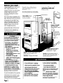
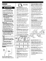
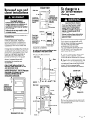
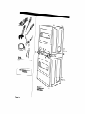
‘ted Drye
lnst ‘IUCbI tiol
stud
c
%s
Part No. 3395339
Before you start...
Check location where dryers will be
used. Proper installation is your
responsibility
The dryer must not be
installed or stored in an area where it
will be exposed to water and/or
weather. Make sure you have
everything
necessary for correct
installation.
Protection from weather: Proper
operation
requires temperatures
above 45°F (7.2”C).
The wiring diagram is located inside
the control panel and access panels.
Each of the dryers is equipped
with a
timer, selector switches and indicator
lights. The timers are set to provide 45
minutes (4 pins) of drying time when
activated
by the coin slide. Timer
cams for 30-minute (6 pins) and 60minute (3 pins) drying timers are
supplied with the unit in the parts
bag. See Pages 7 and 8 for timer
cam changing
instructions.
l/S-inch-NPT plugged
tapping is required.
See “Gas supply
requirements,”
Page 3.
The coin-slide mechanisms,
control
panel lock and key, coin box and
coin box locks and keys are not
included and are available
from
usual industry sources,
Fire Hazard
For your safety, the information in
this manual must be followed to
minimize the risk of fire or explosion
or to prevent property damage,
personal injury or loss of life.
- Do Not store or use gasoline or
other flammable
vapors and
liquids in the vicinity of this or any
other appliance.
- WHAT TO DO IF YOU SMELL GAS:
l
Do Not try to light any
appliance.
l
Do Not touch any electrical
switch; Do Not use any phone
in your building.
l
Clear the room, building or area
of all occupants.
l
Immediately
call your gas
supplier from a neighbor’s
phone. Follow the gas supplier’s
instructions.
- If you cannot reach your gas
supplier, call the fire department.
- Never install dryer up against
draperies or curtains or on carpet.
- Keep any and all items from falling
or collecting
behind the dryer.
Installation and service must be
performed by a qualified installer,
service agency or the gas supplier.
Post this warning in a prominent
location.
It is recommended
that the operator
post, in a prominent location,
instructions for the customer’s use in
the event that the customer smells
gas. This information should be
obtained
from your local gas supplier.
Page 2
Important: Observe all
governing
codes and
ordinances.
-4
Dryers may be
exhausted
from
bottom, rear, left
or right side. See
“Exhaust
requirements,”
Pages 5 - 6.
ded electrical
outlet is
-required.
See “Electrical
requirements,”
Page 4.
Support: The floor must be able to
support the total weight of 3 15
pounds per unit.
Level floor: Maximum floor slope
under dryers - 1 inch.
Fire Hazard
If you install dryers in a garage,
carport, or areas near vehicles
where fumes from gasoline or other
vapors may be present, the vapors
may be heavier than air and
remain near the floor. Place dryers
a minimum of 18 inches above
floor. Check with your building
inspector regarding requirements
for this installation.
Failure to follow these instructions
could result in a fire or explosion.
l
Location must be large enough to
fully open dryer doors. See Page 7 for
recessed area requirements
and
product dimensions.
Electrical Shock Hazard
It is the customer’s responsibility:
l
To contact a licensed electrician.
. To have dryers installed
according
to all national and
local codes and ordinances.
Failure to do so could result in a fire,
electrical
shock or other personal
injury.
Personal Injury Hazard
More than one person is required to
lift, tilt, or move the dryers because
of their weight and size.
Failure to follow these instructions
may result in personal injury.
Tools needed for
installation:
adjustable
wrench
utility knife
Phillips screwdriver
flat-blade
screwdriver
A
n This installation
must conform
with American
National Standard,
National Fuel Gas Code ANSI 2223. llatest edition”, and all local codes
and ordinances.
level
pliers
duct tape
Parts supplied for
hstallation:
2 slide protectors
2 slide extensions
2 bolt and washer
assemblies
8 screws
2,30-minute
cams
2,60-minute
cams
4,3/4” wood screws
Parts owner must
supply:
1 control panel lock and key
2 coin vaults and keys (E.S.D. vault must
have projecting
lock.)
2 coin-slide
mechanisms
(vertical 8)
Parts may be ordered from
Greenwald
Industries, Inc. or
Equipment Systems and Devices,
l
Greenwald
Industries, Inc.
1340 Metropolitan
Avenue
Brooklyn, NY 11237
telephone
(7 18) 82 l-9000 or
toll free (800) 22 l-0982
fax no. (718) 417-7412
l
Equipment Systems and
Devices, Inc.
270 New Jersey Dr.
Fort Washington,
PA 19034
telephone
(2 15) 628-0860 or
toll free (800) 523-1510
fax no. (2 15) 643-4623
Inc.
Gas supply
reauirements
Fire Hazard
These dryers must be connected
to a regulated gas supply.
Failure to do so could result in highpressure gas release, resulting in a
fire or explosion.
l
Have L.P. gas checked
by a
qualified person before installing
the dryer. The L.P. gas supply must
not exceed a pressure of 13”
water column.
l
New flexible tubing should be
used. Reusing old, flexible tubing
might result in possible leaks or
fire hazard.
Failure to follow these instructions
could result in fire or explosion.
l
CODES
G
n The supply line shall be
equipped
with a shutoff valve. This
valve should be located in the same
room as the dryers and should be in a
location that allows ease of opening
and closing. Do Not block access to
shutoff valve.
C
n Check that dryers are
equipped
with the correct burner for
the particular type of gas used.
Burner information will be found on
the rating plate in door well of the
appliance.
If this information
does not
agree with the type of gas available,
see your dealer.
D
a
OBSERVE ALL GOVERNING
AND ORDINANCES.
B
n The desian of this drver has
been certified bv the American
Gas
Association for use at altitudes up to
10,000 feet above sea level at the
B.T.U. rating indicated
on the
model/serial
plate. Burner input
adjustments
are not required when
the dryer is operated
up to this
elevation.
When installed above 10,000 feet, a
four percent (4%) reduction of the
burner B.T.U. rating shown on the
model/serial
plate is required for
each 1,000 foot increase in elevation.
For assistance when converting
to
other gas types and/or installing
above 10,000 feet elevation,
contact
your local service company.
F
H If local codes and ordinances
permit, it is recommended
that new
flexible metal tubing, design-certified
by the American
Gas Association,
be
used for connecting
the dryers to the
gas supply line. (The gas feed pipe,
which extends through the lower rear
of each dryer, is provided with 3/8inch male pipe thread.)
n These dryers are shipped for
use with NATURAL GAS. They are
certified by the American
Gas
Association for manufactured,
mixed
and L.P. (propane
and butane) gases
with appropriate
conversion.
No
attempt shall be made to convert the
appliance
from the gas specified on
the rating plate for use with a
different gas without consulting the
serving gas supplier. Conversion must
be done by a qualified service
technician.
Gas conversion
kit part
numbers are listed on the gas valve
burner base.
E
n Provide a rigid gas supply line
of l/2-inch IPS pipe to the dryer’s
location. If the total length of the
supply line is more than 20 feet, larger
pipe will be needed. For L.P. gas
usage, 3/8-inch, approved
copper
tubing may be used. Pipe-joint
compounds
suitable for use with L.P.
gas should be used.
main gas supply line, a
combination
of fittings must be
used to obtain an in-line connection
to the dryers.
I n Make sure lower edges, back
and sides of the cabinet are free of
obstructions to permit adequate
clearance
of air openings for
combustion
air. See “Recessed area
and closet installation instructions” for
minimum spacing requirements.
J
n For ease of installation,
operating
and servicing (if ever
needed),
adequate
space should be
provided around the dryers.
K
n A l/8-inch,
NPT plugged
tapping, accessible for test gauge
connection,
must be installed
immediately
upstream of the gas
supply connector
to the dryers.
The dryers and their individual shutoff
valves must be disconnected
from
the gas supply piping system during
any pressure testing of that system at
test pressures in excess of l/2 psig
(3.4 kPa).
The dryers must be isolated from the
gas supply piping system by closing
their individual manual shutoff valves
during any pressure testing of the gas
supply piping system at test pressures
equal to or less than l/2 psig
(3.4 kPa).
Page 3
Electrical
requirements
l/0” P
(?.2 mm)
pltre Plug
checking
inlet gas
pressure)
l/2” (12.7 mm)
gas SUPPLY
line (black
iron pipe)
t
/
flexible
connector
(use A.G.A.
desi ncerti 3ied
connector)
\
L
W If the dryers are installed in a
confined area such as a bathroom
or
closet, they must be exhausted to the
outside and provision made for
enough air for combustion
and
ventilation.
(Check governing
codes
and ordinances.
Also refer to the
section of this instruction covering
“Recessed and closet installations.“)
Electrical Shock Hazard
Electrical ground is required on
this appliance.
l
Do Not ground to a gas pipe.
l
Do Not modify the power supply
cord plugs. If plugs will not fit the
outlet, have a proper outlet
installed by a qualified
electrician.
l
Do Not have a fuse in the neutral
or grounding circuit. A fuse in the
neutral or grounding circuit could
result in an electrical
shock.
l
Do Not use an extension cord
with this appliance.
l
Check with a qualified
electrician
if you are in doubt as
to whether the appliance
is
properly grounded.
Failure to follow these instructions
could result in serious injury or
death.
l
If codes permit and a separate
grounding wire is used, it is
recommended
that a qualified
electrician
determine that the
grounding
path is adequate.
OBSERVE ALL GOVERNING
CODES AND ORDINANCES.
A 120-volt, 60-Hz, AC-only, 1.5 or
20-ampere
fused electrical supply is
required. Time-delay fuse or circuit
breaker is recommended.
It is
recommended
that a separate
circuit serving only these appliances
be provided.
Page 4
Kz+;rdmended
grounding
For your personal safety, these dryers
must be grounded.
Each dryer is
equipped
with a power supply cord
having a 3-prong grounding
plug. To
minimize shock hazard, the cords
must be plugged into mating 3-prong
grounding-type
wall receptacles,
grounded
in accordance
with
National Electrical Code ANWNFPA
70 - latest edition”‘,
and all local
codes and ordinances.
If a mating
wall receptacle
is not available,
it is
the personal responsibility and
obligation
of the customer to have a
properly grounded,
3-prong wall
receptacle
installed by a qualified
technician.
See Figure 1.
800
00
8
I
cord
Figure 1
Copies of the standards listed above may be
obtained from:
*American
Gas Association
11515 Wilson Boulevard
Arlington, Virginia 22209
** National Fire Protection
Batterymarch
Park
Quincy, Massachusetts
Association
Exhaust
requirements
Fire/Health Hazard
Do Not use non-metal,
flexible
duct.
l
Do Not use metal duct smaller
than four inches in diameter.
l
Do Not use exhaust hoods with
metal latches.
l
Check that exhaust system is not
longer than specified. Exhaust
system longer than specified will:
- Accumulate
lint.
- Shorten the life of the dryer.
- Reduce the performance,
resulting in longer drying times
and increased energy usage.
Failure to follow specifications
may
result in a fire.
l
Do Not exhaust dryers into a
chimney, furnace cold air duct,
attic or crawl space, or any other
duct used for venting.
9 Clean the exhaust system every
other year.
l
Do Not install flexible duct in
enclosed walls, ceilings or floors.
Accumulated
lint could result in a
fire or cause moisture damage.
. Exhaust dryers outside to prevent
exposure to substances in gas
fuels and combustion
which may
be harmful to your health.
The moisture and lint indoors may
cause:
- FIRE HAZARD from lint collected
in
dryer.
- Moisture damage to woodwork,
furniture, paint, wallpaper,
carpet,
etc.
- Housecleaning
problems and
possible health problems.
Failure to follow these instructions
could result in fire damage or
personal injury.
Metal flexible duct must be fully
extended
and supported
when the
dryers are in final position. DO NOT
KINK OR CRUSH THE DUCT. The metal
flexible duct must be completely
open to allow adequate
exhaust air
to flow.
l
Allow as much room as possible when
using elbows or making turns. Bend
duct gradually to avoid kinking.
Remove excess flexible duct to avoid
sagging and kinking that may cause
reduced airflow.
The external exhaust ducts can be
routed straight out the back of the
dryers. Kits are available
to convert
the external exhaust duct to be
routed right, left or through the
bottom. See Page 6. Product
dimensions and recessed area
requirements
are given on Page 7.
Side or bottom exhaust: The maximum
length of the exhaust system if dryer is
exhausted
out the side or bottom is 16
feet with two external elbows and
hood.
Rear exhaust: The maximum length of
the exhaust system depends on the
type of duct, the number of elbows
and the type of exhaust hood. The
maximum length for both rigid and
flexible duct is shown in the chart.
This chart applies
exhausted
units.
I
MAXIMUM
0
1
2
MAXIMUM
Exhaust materials
supplied.
If dryers are installed in a confined
area such as a bedroom,
bathroom
or closet, they must be exhausted to
the outside and provision must be
made for enough air for combustion
and ventilation.
(Check governing
codes and ordinances.
Also refer to
the “Recessed area and closet
installation instructions,” Page 7.)
An exhaust hood should cap the
exhaust duct to prevent exhausted
air from returning into the dryers. The
outlet hood must be at least 12
inches from the ground or any object
that may be in the path of the
exhaust.
Four-inch outlet hood is preferred.
However, a 2- l/2-inch outlet exhaust
hood may be used. (A 2-l/2-inch
outlet creates greater back pressure
than other hoods.)
A main exhaust duct can be used for
exhausting a group of dryers. Main
exhaust duct should be sized to
remove 200 CFM of air per dryer.
Large-capacity
lint screens of proper
design may be used in the main
exhaust duct if checked
and
cleaned frequently. The room where
the dryers are located should have
make-up air equal to or greater than
the CFM of all the dryers in the room.
Use duct tape
to seal all joints.
are not
0
1
2
only to individually
EXHAUST HOOD TYPE
LENGTH OF 4-INCH
DIAMETER RIGID METAL DUCT
43 FT.
33 FT.
23 FI.
41 FT.
31 FT.
21 FT.
LENGTH OF I-INCH
30 FT.
24 FT.
16 FT.
36 FT.
26 FT.
16 FT.
DIAMETER FLEXIBLE METAL DUCT
29 FT.
23 FT.
15 FT.
24 FT.
18 FT.
10 FT.
For exhaust systems not covered by
the exhaust length chart, see
WhirlDool Service Manual, “Exhausting
Whirlpool Dryers,” Part No. 603197,
available
from your Whirlpool parts
distributor.
Four-inch metal exhaust duct is
required. Plan installation to use the
fewest number of elbows and turns.
,
Service check: The back pressure in
any exhaust system used must not
exceed 0.6 inches of water column
measured with an inclined
manometer
at the point that the
exhaust system connects to the
dryers.
Back-draft damper kits (Part No.
3391910) are available
from your
Whirlpool dealer and should be
installed in each dryer’s exhaust duct
to prevent exhausted
air from
returning into the dryers and to keep
the exhaust balance within the main
exhaust duct. Unobstructed
air
openings are required.
Each exhaust duct should enter the
main duct at an angle pointing in the
direction of the airflow. Ducts
entering from the opposite side
should be staggered
to reduce the
exhausted
air from interfering with the
other ducts.
The maximum angle of each duct
entering the main duct should be no
more than 30”.
Page 5
Product Damage
Keep air openings free of drycleaning fluid fumes. Fumes
create acids which, when drawn
through the dryer heating units,
can damage dryers and loads
being dried.
L
A clean-out
cover should be located
on the main exhaust duct for
periodically
cleaning the exhaust
system.
An exhaust hood should cap the
outside end of the main duct to
prevent exhausted
air from returning
to the dryers. If an exhaust hood
cannot be used, the outside end of
the main duct should have a sweep
elbow directed downward.
If the
main duct travels vertically through
the roof rather than through the wall,
install 180” sweep elbow on the end
of duct at least 2 feet above the
highest part of the building. The
opening wall or roof shall have a
diameter
l/2 inch larger than the
exhaust duct diameter. The exhaust
duct should be centered
in the
opening.
Exhaust duct
connection
Electrical Shock Hazard
Disconnect
both power supply
cords before making these
changes.
Failure to do so may result in
electrical
shock or personal injury.
Determine which direction you need
to attach the exhaust ducts to the
dryers. Both dryers can be exhausted
straight out the back or from the right
or left side. The lower dryer can also
be exhausted
through the bottom.
Next, determine
the length of exhaust
duct you will need to connect the
dryers to exhaust hoods or the main
exhaust.
To connect exhaust duct
straight out the back-
exhaust
hood or
l-l
wall
RI+
2 ft. min.
180
sweep
Attach exhaust duct to each dryer
duct. Then connect exhaust ducts to
exhaust hoods or main exhaust. Use
duct tape to seal all joints.
highest point of
main collector
Do Not install screening
of duct.
Page 6
cap over end
This dryer may be converted
to be
exhausted
out the right or left side or
through the bottom. To convert the
dryer, one of the following kits MUST
be used:
Exhaust Kit No. 279818 (White)
Exhaust Kit No. 279819 (Almond)
Follow the instructions in the Kit to
avoid operational
and personal
hazard.
Recessed area and
closet Installations
Fire/Health Hazard
Exhaust dryers to the outside to
prevent exposure to substances in
the gas fuels and combustion
byproducts
which may be harmful
to your health.
Failire to do so may result in a fire
or health hazard.
Closet view
Side view
Additional
clearances
for
wall, door and
floor moldings
may be
required.
Additional
space may
be needed
for exhaust
elbow.
I- 7”
L
This appliance
may be installed
recessed area.
in a
The installation spacing is the
minimum allowable.
Additional
spacing should be considered
for
ease of installation, servicing and
compliance
with local codes and
ordinances.
If closet door is installed, the minimum
unobstructed
air openings in the top
and bottom are required. Door must
have two centered
openings as
illustrated. Both openings must
provide a minimum of 72 square
inches of unobstructed
airflow as
shown. Louvered doors with
equivalent
air openings are
acceptable.
Opening is
minimum for
closet door.
Louvered
door with
equivalent
air
openings is
acceptable.
Companion
appliance
should be considered.
Product
Electrical Shock Hazard
Disconnect
both power supply
cords from the electric power
supply before making these
changes. Change timing cams
before completing
electrical
connection.
Failure to follow these instructions
may result in electrical
shock or
personal injury.
Each dryer is equipped
with a 45
minute timer cam that provides 45
minutes of drying time when
activated
by the coin slide.
Front view
spacing
No other fuel-burning
appliance
be installed in the same closet.
To change to a
30- or 60-minute
timing cam
You can install the 30-minute or 60minute timing cam (shipped with
each dryer) as follows:
may
1. Unlock control panel. Lift up and
rotate out from cabinet. Control
to cabinet.
panel WIII STIIIDe attached
dimensions
Side view
2. Reach into control panel area. Use
a Phillips screwdriver to loosen (but
not remove) timer mounting bracket
screw. Lift up to remove timer
assembly and bracket from cabinet.
FOR CLOSET INSTALLATIONS, TO
PREVENT LARGE AMOUNTS OF LINT
AND MOISTURE FROM
ACCUMULATING, TO MAINTAIN
DRYING EFFICIENCY, AND TO PREVENT
EXPOSURE TO POSSIBLE HEALTH
HAZARDS, DRYERS MUST BE
EXHAUSTED OUTDOORS.
r
ratchet
tooth
+
4
0”
approx.
Additional
clearances may
be required for
wall. door and
floor moldings if
external exhaust
elbow is used.
Rear view
pJ
llB/
Recessed
3. Turn the timing cam by hand until
the ‘I/“-shaped
notch lines up below
the ratchet tooth.
kttom
exhaust
front view
Page 7
timyg
ratchet
Now start...
cam a
With dryers in laundry
tooth
area.
1
n
Check that each leg is
approximately
1 inch from base.
line up notch
to clear
ratchet tooth.
\
drive lug
2.
Wipe the interior of the drums
thoroughly with a damp cloth
3.
Install coin vaults and locks (not
supplied) into meter case openings.
4. Insert a narrow, flat-blade
screwdriver under the timing cam
near the clock shaft. Gently lift cam
straight up and off shaft making sure
that the “V-shaped
notch clears the
ratchet tooth.
5. Place new cam (hub side down)
over clock shaft Line up flat side of
shaft with flat side of cam hole.
Check that drive lug is in place.
6.
Turn cam until “V-shaped
lines up with ratchet tooth.
notch
4.
Install control
supplied).
panel
Open control panel and rest it on the
bottom edge of the opening. Attach
slide extension (with flange pointing
down) to one of the coin-slide
mechanisms,
Insert the coin-slide
mechanism
through the opening to
the left of the control panel.
lock and key (not
Electrical Shock Hazard
Control panel must be closed and
locked at all times.
Failure to do so could result in
serious injury or death.
7. Press cam down in place on motor
shaft. Make sure that “V”-shaped
notch clears the ratchet tooth,
7.
Secure coin-slide mechanism
from
inside the control panel using the
3/l 6” bolt and washer supplied. Install
coin box.
8.
Reattach the timer bracket
assembly; tighten the screws,
9. Repeat
10.
8
steps for other timer
Close and lock the control
n
Repeat Steps 6 and 7 for the other
coin-slide mechanism.
Close control
panel.
panel.
If you wish to change the 45minute
dryer timing cams to either 30- or 60minute timing cams, see “To change
to a 30- or 60-minute timing cam,”
Pages 7 and 8. Complete
all of the
steps given in that section before
going to Step 6.
9..
Electrical Shock Hazard
Disconnect electrical
power at the
service panel (fuse box or circuit
breaker box).
Failure to do so could result in
serious injury or death.
Page 8
Insert top of wire guard into holes on
each side of the coin-slide
mechanism.
Insert screws through
hooked ends of guard and tighten.
Repeat for other wire guard.
14 w
Remove
pipes.
the red caps from the gas
800
00
8
0
16.
Check levelness of dryers by placing
a carpenter’s
level on top of the
dryers or collar, first side to side, then
front to back. If dryer is not level,
adjust the front legs up or down.
Make the final check with the level.
Plug power supply cords into
grounded
outlets. Turn on electrical
power supply.
11.
Connect gas supply to each dryer.
Use pipe-joint compound
resistant to
the action of Natural and L.P. gas for
gas connections.
Floor Damage
Slide dryers onto cardboard
or
hardboard
before moving across
floor.
Failure to do so may result in
damage to floor covering.
Move unit to its permanent
location.
12.
Open the shutoff valves
supply lines.
in the gas
Fire Hazard
Do Not use an open flame to test
for leaks from gas connections.
Checking for leaks with a flame
may result in a fire or explosion.
13.
Use a brush and liquid detergent
to
test all gas connections
for leaks.
Bubbles around connections
will
indicate a leak. If a leak appears,
shut off gas valve controls and adjust
connections.
Then check
connections
again. NEVER TEST FOR
GAS LEAKS WITH A FLAME. Close the
access panels.
All connections
must be wrenchtightened.
15.
Turn one dryer on to remove air from
the gas supply line. Using a full heat
cycle (not the air cycle), let the dryer
run for at least five minutes, If the
burner does not ignite and you can
feel no heat inside the dryer, shut off
the dryer for five minutes. Check that
all supply valve controls are in ‘ON”
position and that the power supply
cord is plugged in. Repeat the fiveminute test.
17
n TO exhaust the dryers, see
“Exhaust requirements”
and “Exhaust
duct connection,”
pages 5 and 6.
Personal Injury Hazard
To prevent tipping, tether bracket
must be secured to wall studs or
concrete wall.
Failure to do so could result in
personal injury.
Tether bracket, located
rear of the top dryer.
at
w
Attach both ends of tether located at
the rear of the top dryer to a secured
2x4.
Page
9
77.
IO. 7 7.
14.
16.7.9.
Check to ma& Sure you have all Your
tools.
7.
0. 77.
correspond
with steps.
If dryers do not
operate properly...
Check
the following
1. Electrical
Move dryers to a
new location...
to be sure that:
supply is connected.
2. Circuit breakers
fuses blown.
are not tripped
Floor Damage
Slide dryers onto cardboard
or
hardboard
before moving across
floor.
Failure to do so may result in
damage to floor covering.
or
3. Doors are closed.
4. Timer has been
actuated,
5. Controls are set in a running
“ON” position.
or
6. Gas shutoff valves are open
on dryer and supply line.
both
l
l
l
l
l
l
l
Shut off electric supply to dryers.
Disconnect
power supply cords.
Tape securely to dryer.
Shut off the gas supply valves in the
gas supply line.
Disconnect
gas pipe and fittings
from dryer and cap the gas supply
line. Tape end of dryer gas pipes.
Tape the drums to the front panel.
Tape doors.
Adjust leveling legs all the way in.
Before installing dryers in a new
location, check with your gas supplier
or dealer to see that your dryer is
equipped
with the correct burner for
the particular type of gas in your new
building. Burner information
may be
found on the rating plate in the door
well of the dryer.
If you need
assistance...
The Whirlpool Consumer Assistance
Center will answer any questions
about operating
or maintaining
your
dryers not covered in the Installation
Instructions. The Whirlpool Consumer
Assistance Center is open 24 hours a
day, 7 days a week. Just dial l-(800)
253-l 301 - the call is free.
When you call, you will need the
dryer model number and serial
number. Both numbers can be found
on the serial/rating
plate located in
the door well behind the dryer door
and on the front of the opening.
Part No. 3395339
0 1994 Whirlpool Corporation
Prepared
by Whirlpool
Corporation,
Benton
Harbor,
Michigan
49022
Printed in USA