1
Operating and installation instructions
Range hood
DA 186,
DA 188,
DA 189
To avoid the risk of personal injury
or damage to the appliance, it is
essential that you read these
operating instructions before
installation and use.
en - CA
M.-Nr. 07 837 910
Contents
Caring for the environment . . . . . . . . . . . . . . . . . . . . . . . . . . . . . . . . . . . . . . . . . . 3
IMPORTANT SAFETY INSTRUCTIONS. . . . . . . . . . . . . . . . . . . . . . . . . . . . . . . . . 4
Guide to the appliance / Operation . . . . . . . . . . . . . . . . . . . . . . . . . . . . . . . . . . . 8
Operation . . . . . . . . . . . . . . . . . . . . . . . . . . . . . . . . . . . . . . . . . . . . . . . . . . . . . . . . . 9
Operation . . . . . . . . . . . . . . . . . . . . . . . . . . . . . . . . . . . . . . . . . . . . . . . . . . . . . . . 10
Cleaning and care . . . . . . . . . . . . . . . . . . . . . . . . . . . . . . . . . . . . . . . . . . . . . . . . 11
Housing . . . . . . . . . . . . . . . . . . . . . . . . . . . . . . . . . . . . . . . . . . . . . . . . . . . . . . . . . 11
Grease filters . . . . . . . . . . . . . . . . . . . . . . . . . . . . . . . . . . . . . . . . . . . . . . . . . . . . . 11
Odor Filters . . . . . . . . . . . . . . . . . . . . . . . . . . . . . . . . . . . . . . . . . . . . . . . . . . . . . . 13
Changing lamps . . . . . . . . . . . . . . . . . . . . . . . . . . . . . . . . . . . . . . . . . . . . . . . . . . 14
Customer service . . . . . . . . . . . . . . . . . . . . . . . . . . . . . . . . . . . . . . . . . . . . . . . . . 15
Appliance dimensions . . . . . . . . . . . . . . . . . . . . . . . . . . . . . . . . . . . . . . . . . . . . . 16
Distance between cooktop and hood . . . . . . . . . . . . . . . . . . . . . . . . . . . . . . . . . . 17
Installation . . . . . . . . . . . . . . . . . . . . . . . . . . . . . . . . . . . . . . . . . . . . . . . . . . . . . . 18
Electrical connection . . . . . . . . . . . . . . . . . . . . . . . . . . . . . . . . . . . . . . . . . . . . . . 24
Air extraction . . . . . . . . . . . . . . . . . . . . . . . . . . . . . . . . . . . . . . . . . . . . . . . . . . . . 25
Technical data . . . . . . . . . . . . . . . . . . . . . . . . . . . . . . . . . . . . . . . . . . . . . . . . . . . 27
2
Caring for the environment
Disposal of packing material
Disposal of an old appliance
The cardboard box and packing
materials protect the appliance during
shipping. They have been designed to
be biodegradable and recyclable.
Please recycle.
Old appliances may contain materials
that can be recycled. Please contact
your local recycling center about the
possibility of recycling these materials.
To prevent suffocation of children,
ensure that any plastic wrappings,
bags, etc. are disposed of safely
and kept out of their reach.
Before discarding an old hood,
unplug it from the outlet and cut off
its power cord to prevent hazards.
3
IMPORTANT SAFETY INSTRUCTIONS
READ AND SAVE THESE
INSTRUCTIONS
Keep these operating instructions in
a safe place and pass them on to any
future user.
Read these Instructions carefully
before installing or using the
Ventilation System.
~ This appliance is intended for
residential use only. Use the appliance
only for its intended purpose.
~ This appliance complies with current
safety requirements. Improper use of
the appliance can lead to personal
injury and material damage.
,CAUTION
For General Ventilating Use
Only. Do Not Use To Exhaust
Hazardous Or Explosive
Materials And Vapors.
~ This appliance is designed to vent
cooking smoke and odors only.
~ This appliance is suitable for
installation above gas or electric
cooking surfaces.
~ This appliance is not designed for
maritime use or for use in mobile
installations such as recreational
vehicles or aircraft.
4
,WARNING
TO REDUCE THE RISK OF
FIRE, ELECTRIC SHOCK, OR
INJURY TO PERSONS,
OBSERVE THE FOLLOWING:
~ a) Use this appliance only in the
manner intended by the manufacturer.
If you have questions, contact Miele.
~ b) Before servicing or cleaning the
appliance, switch power off at the service panel and lock the service
disconnecting means to prevent power
from being switched on accidentally.
When the service disconnecting means
cannot be locked, securely fasten a
prominent warning device, such as a
tag, to the service panel.
~ c) Be certain your appliance is
properly installed and grounded by a
qualified technician.
To guarantee the electrical safety of this
appliance, continuity must exist
between the appliance and an effective
grounding system. It is imperative that
this basic safety requirement be met. If
there is any doubt, have the electrical
system of the house checked by a
qualified electrician.
IMPORTANT SAFETY INSTRUCTIONS
~ d) Before connecting the appliance
to the power supply make sure that the
voltage and frequency listed on the
data plate correspond with the
household electrical supply.
This data must correspond to prevent
appliance damage. If in doubt consult a
qualified electrician.
~ e) Installation work and repairs
should only be performed by a qualified
technician in accordance with all
applicable codes and standards.
Repairs and other work by unqualified
persons could be dangerous.
~ f) Only open the housing as
described in the enclosed "Installation
diagram" and in the "Cleaning and care"
section of this manual. Under no
circumstances should any other parts
of the housing be opened. Tampering
with electrical connections or
components and mechanical parts is
highly dangerous to the user and can
cause operation faults.
~ g) Before discarding an old
appliance, disconnect it from the power
supply and remove the power cord to
prevent hazards.
Use
,WARNING
TO REDUCE THE RISK OF A
COOKTOP GREASE FIRE:
~ a) Never leave surface units
unattended at high settings. Boilovers
cause smoking and greasy spillovers
may ignite. Heat oils slowly on low or
medium settings.
~ b) Always turn the hood on when
cooking at a high heat.
~ c) Clean the ventilation hood
frequently. Grease should not be
allowed to accumulate on the fan or
filter.
~ d) Use the proper pan size. Always
use cookware appropriate for the size
of the cooking area.
~ e) Do not flambé or grill with an
open flame beneath the hood.
Flames could be drawn up into the
hood by the suction and the grease
filters may catch fire.
5
IMPORTANT SAFETY INSTRUCTIONS
,WARNING
TO REDUCE THE RISK OF
INJURY TO PERSONS IN THE
EVENT OF A COOKTOP
GREASE FIRE, OBSERVE THE
FOLLOWING*
~ Do not allow children to play with or
~ a) SMOTHER FLAMES with a close
fitting lid, cookie sheet, or metal tray
then turn off the burner.
BE CAREFUL TO PREVENT BURNS.
If the flames do not go out immediately,
EVACUATE AND CALL THE FIRE
DEPARTMENT.
~ Never operate gas burners without
operate the appliance or its controls.
Supervise its use by the elderly or
infirm.
~ Always turn on the hood when using
the cooktop to prevent damage from
condensation.
~ b) NEVER PICK UP A FLAMING
PAN - You may be burned.
cookware. Turn the burner off when not
in use. Adjust the burner so that the
flames do not extend beneath the
cookware. Do not overheat the
cookware, e.g. when using a wok. The
hood can be damaged due to
excessive heat from the burners and
the cookware.
~ c) DO NOT USE WATER, including
~ Do not use the hood without the
wet dishcloths or towels - a violent
steam explosion will result.
~ d) Use a fire extinguisher ONLY if:
1) You have a class ABC
extinguisher, and you know how to
operate it.
2) The fire is small and contained in
the area where it started.
3) The fire department is being
called.
4)You can fight the fire with your
back to an exit.
* Based on "Kitchen Firesafety Tips"
published by NAFTA
6
grease filters in place.
~ Do not use a steam cleaner to clean
the hood. Steam could penetrate
electrical components and cause a
short circuit.
IMPORTANT SAFETY INSTRUCTIONS
Installation
~ g) Do not install this hood over
cooktops that burn solid fuel.
,WARNING
TO REDUCE THE RISK OF
FIRE, ELECTRIC SHOCK, OR
INJURY TO PERSONS,
OBSERVE THE FOLLOWING:
~ a) Installation work and electrical
wiring must be done by qualified
person(s) in accordance with all
applicable codes and standards,
including fire-rated construction.
~ b) Sufficient air is needed for
combustion and exhausting of gases
through the flue (chimney) of fuel
burning equipment to prevent back
drafting. Follow the heating equipment
manufacturer’s guideline and safety
standards such as those published by
the National Fire Protection Association
(NFPA) and the American Society for
Heating, Refrigeration and Air
Conditioning Engineers (ASHRAE), and
the local code authorities.
~ h) Provided a larger distance is not
given by the manufacturer of the
cooktop, follow the minimum safety
distances between a cooktop and the
bottom of the hood given in the
"Appliance dimensions" section of this
manual.
If local building codes require a greater
safety distance, follow their
requirement.
If there is more than one appliance
beneath the hood and they have
different minimum safety distances
always select the greater distance.
When installing a wood or laminate
decor panel onto the cooker hood,
regard the cooktop manufacturer’s
advice on the use of easily flammable
material above the cooktop.
~ i) Never connect an exhaust hood to
an active chimney, dryer vent, vent flue,
or room ventilating ductwork.
~ c) When cutting or drilling into the
wall or ceiling, do not damage electrical
wiring and other hidden utilities.
~ j) Seek professional advice before
~ d) Ducted hoods must always be
vented to the outdoors.
~ k) Any fittings, sealant, or materials
connecting an exhaust hood vent to an
existing, inactive chimney or vent flue.
~ e) Do not use this hood with any
solid-state speed control device.
used to install the ductwork must be
made of approved non-flammable
materials.
~ f) Do not use an extension cord to
connect the appliance to electricity.
Extension cords do not guarantee the
required safety of the appliance,
(e.g. danger of overheating).
,WARNING
TO REDUCE THE RISK OF
FIRE USE ONLY METAL
DUCTWORK.
7
Guide to the appliance / Operation
8
Guide to the appliance / Operation
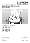
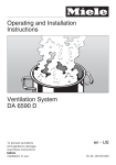
a Recirculation grille
(for recirculation mode only)
Operation
b Exhaust connection
Switching the fan on
c Installation bracket
d Folding vapour canopy
for installation of a cabinet door
e Deodorizing filter
(accessory available to order for
recirculation mode operation)
f Cooktop lighting
g Grease filter
h Control panel
^ Open the vapour canopy.
The fan comes on at power level "2".
^ Use the buttons to select the desired
power level.
For air exhaust and circulation, it is
recommended that you let the fan
continue to run for several minutes after
cooking is completed.
This helps clear the kitchen air of any
remaining vapours and odours.
^ To switch off the fan
– close the vapour canopy, or
– press the "OFF" button longer.
^ To switch the fan back on, press one
of the buttons "1" to "3".
Switching on the lighting
The cooktop lighting can be switched
on and off independently of the fan.
^ Open the vapour canopy.
The lighting switches on.
^ To switch off the lighting
– close the vapour canopy, or
– press the "n" button.
9
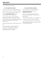
Operation
The range hood operates
. . . in air extraction mode:
. . . in air recirculation mode:
The air is drawn in and cleaned by the
grease filters and then directed outside.
The air drawn in is cleaned by the
grease filters and then by two
deodorizing filters.
If your air extraction system does not
have a non-return flap, one is
provided with the range hood.
A non-return flap in the ventilation
system ensures that when the range
hood is shut off no unwanted exchange
can occur between room air and
outdoor air.
It is closed when the range hood is shut
off.
When the hood is switched on, the
non-return flap opens so that the
exhaust air can be transported
unimpeded to the outside.
10
The air is returned to the kitchen
through an opening in the top of the
range hood.
The deodorizing filters are available as
accessories (see "Technical data").
In recirculation operation, ensure that
the deodorizing filters are in place; see
"Care and Cleaning".
Cleaning and care
,WARNING. TO REDUCE THE
RISK OF ELECTRIC SHOCK
OBSERVE THE FOLLOWING:
Before servicing and repairing the
range hood, disconnect it from the
household electrical supply,
– by switching off the house panel
circuit breaker
or
– by completely unscrewing
screw-type fuses from the
house fuse panel
Grease filters
The re-usable metal grease filters in the
appliance trap the solid components
present in cooking vapour (grease,
dust, etc.), and this helps keep the
exhaust hood clean.
We recommend cleaning the grease
filters every 3-4 weeks, before the
residue solidifies.
A filter with excessive grease carries
the risk of fire.
Housing
The surfaces and control panel are
sensitive to scratching and cutting.
To keep from damaging them, it is
important to read the following
instructions.
Use only a soft cloth with some dish
liquid and warm water to clean all
surfaces and the control panel.
Dry all surfaces with a soft cloth.
In the control panel area, do not use
excess moisture in cleaning, to
prevent dampness from getting into
the electronics.
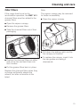
^ Open the grease filter locking clips
and remove the filter downwards.
To prevent damage to the filter and
the cooking surface, hold the filter
securely when handling it.
Avoid:
– cleaning products that contain
washing soda, acids, bleach or
solvents,
– abrasive cleansers, such as scouring
powder or scouring liquid, scrubbing
sponges, such as pot scrubbers, or
used sponges that still contain
abrasive cleanser residue.
11
Cleaning and care
Washing the grease filter by hand
^ Clean the grease filters with a dish
brush dipped in a mixture of warm
water and a mild dish liquid.
Do not use undiluted or concentrated
dish liquid.
Do not use the following:
– lime removers,
– scouring powder, scouring liquid, or
any corrosive all-purpose cleaner.
– oven spray,
Washing grease filters in the
dishwasher
^ Place the filter vertically in the lower
basket, making sure that the spray
arm is not blocked.
Use a wash program with a max.
temperature of 150°F (65°C). In a
Miele dishwasher use the "Normal"
program.
Use the recommended amount of
dishwasher detergent. Overuse could
destroy the filter.
If you use the dishwasher to clean
the grease filters, some discoloration
may occur on their inside surfaces,
depending on the detergent used.
This has no effect on their efficiency.
^ After cleaning, lay the grease filters
on an absorbent surface to dry.
^ With the filters removed, clean
accumulated grease from accessible
areas of the housing. This reduces
the fire hazard.
12
Cleaning and care
Odor Filters
Note:
If the range hood is set up for
recalculation operation, two DKF 14-1
charcoal filters must be added to the
grease filters.
The vapour canopy may be removed
for better accessibility.
^ Open the vapour canopy.
^ Open the vapour canopy.
^ Remove the grease filters.
^ Take the charcoal filters out of their
packaging.
^ Pull down the sliding catch and tip
the canopy out forward.
^ Position the charcoal filters on either
side of the fan and twist them into
their holders.
^ To replace the canopy, insert it into
the top guides and swing it
downwards.
^ Put the grease filters back in place.
Replace the charcoal filters when they
no longer sufficiently absorb the
odours, but after six months at the
latest.
13
Cleaning and care
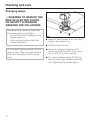
Changing lamps
,WARNING TO REDUCE THE
RISK OF ELECTRIC SHOCK
OR INJURY TO PERSONS
OBSERVE THE FOLLOWING:
Disconnect the exhaust hood from
the power supply as follows:
– shut off the circuit breaker at the
house panel, or
– fully unscrew the fuse from the
house fuse panel.
^ Remove both screws from the lamp
holder decorative ring.
^ Pull the lamp unit out.
The halogen lights become very hot
when in use. They can cause burns
even after being shut off for some
time.
14
^ Push the halogen lamp out of its
mounting from the back. Take care
not to let it fall on the cooktop.
^ Fir a new halogen lamp (20 W) into
the mounting, and replace the lamp
unit, tightening its screws again.
Customer service
For faults you cannot correct yourself,
please contact the Miele Factory Repair
Service.
The telephone number for the
Factory Repair Service is listed on
the back cover of these operating
instructions.
Customer service will require the model
designation and serial number of your
range hood. These can be found on the
data plate, visible when the grease
filters are removed.
15
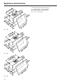
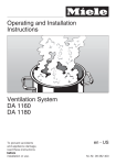
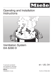
Appliance dimensions
* Cabinet panel dimensions
Air extraction connection
C 4 3/4" (120 mm).
DA 186
DA 188
DA 189
16
Appliance dimensions
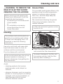
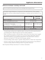
Distance between cooktop and hood
Do not install this exhaust hood over cooktops burning solid fuel.
Provided a larger distance is not given by the manufacturer of the cooktop,
follow the minimum safety distances between a cooktop and the bottom of the
hood:
Miele Cooktops
Non-Miele
Cooktops
Electric Cooktops
24" (610 mm)
Electric Barbeques and Fryers
26" (660 mm)
Multiburner Gas cooktops
< 43,000 BTU (12.6 KW)
and no burner > 15,000 BTU (4.5 KW)
26" (660 mm)
30" (760 mm)
Single burner (Wok) < 20,500 BTU (6 KW)
26" (660 mm)
30" (760 mm)
All other gas cooktops
30" (760 mm)
– If several gas surfaces are installed under the hood, the total output must be
considered when determining the minimum safety distance.
– When installing a wood or laminate decor panel onto the cooker hood, regard
the cooktop manufacturer’s advice on the use of easily flammable material
above the cooktop. If not otherwise specified in the instructions, ensure a
distance of at least 30” (760 mm) from the gas cooktop.
– If local building codes require a greater safety distance, follow their requirement.
– If there is more than one appliance beneath the hood and they have different
minimum safety distances always select the greater distance.
See "Important Safety Instructions" for further information.
17
Installation
Before installation, read the
information on "IMPORTANT SAFETY
INSTRUCTIONS".
Under certain conditions there is a
risk of carbon monoxide poisoning,
especially if you operate the range
hood simultaneously with an open
fireplace.
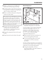
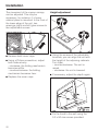
^ Take out the grease filter and remove
the protective foil from the filter
frame.
Installing the cabinet door
^ Open the vapour canopy.
^ Pull the sliding catch forward to
release the canopy and swing it
forward and upwards.
18
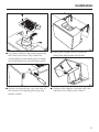
^ Cut the drilling template for the front
door to size, lay it on the inside of the
door and pre-drill the holes as
marked.
^ Using suitable screws, attach the
cabinet door to the vapour canopy.
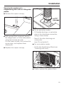
Installation
Adjusting depth
To install a plywood backing
The whole weight of the installed
ventilation system has to be
supported by the mounting plates.
They must be firmly attached to stud
framing behind the drywall. If studs
are not available directly behind
both mounting plates, a plywood
backing (min. 2" (51 mm) thick)
spanning at least two studs must be
installed. Failure to adequately
support the weight as stated may
result in the ventilation system falling
off the wall, causing personal injury
and property damage.
(If plywood backing is not needed,
proceed to "Wall attachment".)
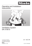
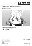
^ The depth of the unit ("T" in the
diagram) can be adjusted from
10 13/16" to 14 3/16" (275 to 360 mm) by
means of the adjustable brackets..
^ Slightly loosen the screws holding the
brackets.
^ Pull the brackets out to the desired
depth "T".
^ Tighten the screws again.
^ To align the depth on the underside
of the hood, loosen the screws on the
angle plate and move it to the
position required.
^ If the range of adjustment is
insufficient, unscrew the bracket
completely, rotate it, and use the
longer side.
^ Determine and mark the top edge of
the appliance. It must be at least
S + 17 3/4" (S + 450 mm) in order to
comply with the safety height (see
"Appliance Dimensions").
^ Tighten the screws again.
19
Installation
^ Make a cutting line 13" (330 mm)
below the the top edge marking.
Wall attachment
^ Find the studs to the left and right of
the appliance location by tapping the
wall or using a stud finder.
^ Mark a vertical cutting line along the
center of each stud.
Be careful not to damage any wiring
or plumbing that may be located
behind the wall. Make sure that the
power supply to the area where this
installation is being performed has
been turned off at the breaker panel
before cutting into the wall.
^ Remove the drywall between the
cutting lines and replace it with
plywood of a matching thickness
(min. 2" (51 mm) thick).
^ Screw the plywood firmly to the wall
studs.
^ Tape the joints and refinish the wall.
^ Cut the wall attachment drilling
template and place it on the wall.
The top edge of the trimmed template
marks the top edge of the unit. To
maintain a safe height above the
cooktop, it must not be lower than
S + 17 3/4" (S + 450 mm) (see
"Appliance Dimensions").
^ Mark and drill the four locations for
the mounting plate (C 3 mm).
^ Fix the mounting plate to the wall
using the 5.2 x 50 mm screws
provided.
Another drilling template is provided for
connecting the range hood to adjoining
cabinets or for fitting side panels.
^ Using the template, drill two
mounting holes in the side cabinet or
side panel (C 2 mm).
20
Installation
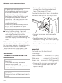
^ For Recirculation the reducing collar
with the non-return flap must be
removed by unscrewing the screws
and installing the recirculation grille.
^ Hang the range hood in position
using the adjustable brackets.
^ Using a screw driver, pry out one of
the covers for feeding through the
power cable.
^ Position the vapour canopy with the
cabinet front fitted and close it.
21
Installation
The movement of the vapour canopy
can be adjusted. This may be
necessary, for instance, if a heavy
cabinet panel is mounted. In the front of
the lower edge of the unit, two
openings (right and left) give access to
two adjustment screws.
^ Remove both cover caps.
^ Using a Philips screwdriver, adjust
both sides evenly:
- clockwise: the folding mechanism
becomes stiffer.
- counterclockwise: the folding
mechanism becomes freer.
Height adjustment
^ Using the screws of the adjustable
brackets, you can align the unit with
the height of the adjoining cabinets.
Turn them
– counterclockwise: The unit is
raised.
– clockwise: the unit is lowered.
^ If necessary, adjust the depth again.
^ Replace the cover caps.
^ Fix the hood to the wall using the
5.2 x 50 mm screws provided.
22
Installation
Securing the appliance to
neighbouring wall units or fitting side
panels
^ Remove the vapour canopy.
^ For air extraction mode:
^ With grease filters removed, secure
the range hood, or fit the side panels,
using two screws per side.
For the lower screws, first remove the
screw caps, and replace them
afterwards.
^ Replace the vapour canopy.
– Fit flexible ducting or a extraction
pipe to the discharge connection,
using a hose clamp.
– Now fit the other discharge air
connection.
(see "Air extraction")
^ For recirculation mode:
– Fit the two deodorizing filters (see
"Cleaning and care").
^ Finally, replace the grease filters.
23
Electrical connection
All electrical work should be
performed by a qualified electrician
in strict accordance with national
and local safety regulations.
Installation, repairs and other work
by unqualified persons could be
dangerous. The manufacturer can
not be held responsible for
unauthorized work.
Ensure that power to the appliance
is OFF while installation or repair
work is performed.
^ Verify that the voltage, load and
circuit rating information found on the
data plate (located behind the
grease filter), match the household
electrical supply before installing the
hood.
If there is any question concerning the
electrical connection of this appliance
to your power supply, please consult a
licensed electrician or call Miele’s
Technical Service Department. See
back cover for contact information.
WARNING:
THIS APPLIANCE MUST BE
GROUNDED
Important
To increase security before the
machine is installed, it is
recommended to install a protective
switch (30 mA).
CAUTION
Connect only to a 15-ampere branch
circuit.
24
^ Remove the vapour canopy and the
grease filters from the range hood
(see “Cleaning and Care”).
The electrical junction box is located on
the inside rear right of the range hood.
^ Loosen the screws and remove the
cover.
^ Feed the power line from your house
installation through the cable opening
in the casing.
^ Connect the cables to the terminal
clamps.
Important
The hood must be hard wired
accordingly:
Black/Red wire:. . . . connect to L1 (live)
White wire: . . . . . connect to N (neutral)
Green wire: . . connect to GND (ground)
^ Close up the junction box again and
re-install the grease filters and the
vapour canopy.
Air extraction
,WARNING
Danger of toxic fumes.
Gas cooking appliances release
carbon monoxide that can be
harmful or fatal if inhaled.
To reduce the risk of fire and to
properly exhaust air, the exhaust
gases extracted by the hood
should be vented outside of the
building only.
Do not vent exhaust air into
spaces within walls or ceilings or
in attics, crawl spaces or garages.
To reduce the risk of fire, only use
metal ductwork.
Please read and follow the
"IMPORTANT SAFETY
INSTRUCTIONS" to reduce the risk of
personal injury. Follow all local building
codes when installing the hood.
25
Exhaust ducting and connections
Use smooth or flexible pipework made
from approved non-flammable
materials for exhaust ducting.
To achieve the most efficient air
extraction and quietest noise levels,
consider the following:
– The diameter of the ductwork should
not be less than 4 3/4" (120 mm).
– If flat ducting is used, the cross
section must not be smaller than the
cross section of the ventilation
exhaust.
– The ducting should be as short and
straight as possible.
– Use ductwork with a wide radius.
– The exhaust duct must not be bent
or compressed.
– Make sure all connections are
secure.
– Where the ductwork is horizontal, it
must slope away from the hood at
least 1/8" per foot (1 cm per meter) to
prevent condensation dripping into
the appliance.
Air extraction
– If the exhaust is ducted through an
outside wall, a Miele Telescopic Wall
Vent can be used.
– If the exhaust is ducted into an
inactive flue, the air must be expelled
parallel to the flow direction of the
flue.
Never connect an exhaust hood to
an active chimney, dryer vent, flue,
or room venting ductwork. Seek
professional advice before
connecting an exhaust hood vent to
an existing, inactive chimney or vent
flue.
Important
If the ductwork runs through rooms,
ceilings, garages, etc. where
temperature variations exist, it may
need to be insulated to reduce
condensation.
26
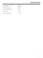
Technical data
Total connected load. . . . . . . . . . 260 W
Fan motor . . . . . . . . . . . . . . . . . 220 W
Cooktop lighting . . . . . . . . . . 2 x 20 W
Power supply voltage . . . . . . . . . 120 V
Cycles (Hz) . . . . . . . . . . . . . . . . ~ 60 Hz
Fuse rating (amps) . . . . . . . . . . . . . 15 A
27
Alteration rights reserved / 2810
M.-Nr. 07 837 910 / 00