1
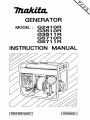
GENERATOR
MODEL : G341 O R
G351O R
G3511 R
G571 O R
G5711 R
INSTRUCTION MANUAL
I ISSUE EMD-GU0937 ]
1 3229020055 I
The engine exhaust from this product
contains chemicals known to the State of
California to cause cancer, birth defects or
other reproductive harm.
I
I
California Emission Control Warranty Statement
[This warranty does not apply in any other state.)
YOUR WARRANTYRIGHTS AND OBLIGATIONS
The California Air Resources Board and Makita U.S.A., Inc. are pleased to explain the
emission control warranty on your 1995 utility and /or lawn and garden equipment
engine. In California, new utility and lawn and garden equipment engines must be
designed, built and equipped to meet the State’s stringent anti-smog standards. Makita
U.S.A., Inc. must warrant the emission control system on your utility and/or lawn and
garden equipment engine for the periods of time listed below provided there has been no
abuse, neglect or improper maintenance of your utility and/or lawn and garden equipment
engine.
Your emission control system includes parts such as the carburetor or fuel injection
systems, the ignition system and the catalytic converter. Also included are the hoses, and
connectors and other emission-related assemblies.
Where a warrantable condition exists, Makita U.S.A.,Inc. will repair your utility and/or
lawn and garden equipment at no cost to you including diagnosis, parts and labor.
MANUFACTURER’S WARRANTY COVERAGE :
The 1995 and later utility and/or lawn and garden equipment engines are warranted for
two years. If any emission-related part on your engine is defective, the part will be
repaired or replaced by Makita U.S.A.,inc.
0WNER’S WARRANTY RESPONSIBILITIES :
As the utility and lawn and garden equipment engine owner, you are responsible for the
performance of the required maintenance listed in your owner’s manual. Makita U.S.A.,
Inc. recommends that you retain all receipts covering maintenance on your utility and /or
lawn and garden equipment engine, but Makita U.S.A., Inc. cannot deny warranty solely
for the lack of receipts or for your failure to ensure the performance of all scheduled
maintenance.
As the utility and/or lawn and garden equipment engine owner, you should be aware,
however, that Makita U.S.A., Inc. may deny you warranty coverage if your utility and/or
lawn and garden equipment engine or a part has failed due to abuse, neglect, improper
maintenance or unapproved modifications.
You are responsible for presenting your utility and/or lawn and garden equipment engine
to a Makita U.S.A., inc. service center as a problem exists. The warranty repairs should
be completed in a reasonable time, not to exceed 30 days.
If you have any questions regarding your warranty rights and responsibilities, you should
contact a Makita Factory Service Center Manager nearest you. A list of the Factory
Service Center locations and phone numbers is provided below for your convenience.
LIMITED WARRANTY
-California OnlyMakita U.S.A., Inc., a distributor of utility and lawn and garden equipment in the U.S.,
warrants to the owner of 1995 and later utility andlor lawn and garden equipment engines
that the engine( 1) has been designed, built, and equipped at the time of manufacture so as
to conform with the applicable regulations of the California Air Resources Board and, (2)
is free from defects in materials and workmanship which may cause it to fail to conform
with those regulations as applicable according to the terms and conditions stated below.
WARRANTY PERIOD
The warranty period begins on the date which the utility andlor lawn and garden
equipment engine is delivered to the original retail purchaser and ends two years after that
date. During this two year period Makita U.S.A.., inc. warrants to the original retail
purchaser and each subsequent purchaser that the engine is free from defect in material
and workmanship that can cause the failure of a warranted emission-related part.
WHAT IS COVERED UNDER THIS WARRANTY
Repair and/or replacement of any warranted emission-related part will be performed at no
charge provided the work is performed at an authorized warranty station. There will also
be no charge for any diagnostic labor performed at an authorized warranty station which
leads to the determination that a warranted emission-related part is defective.
Any warranted part which is not scheduled for replacement as required maintenance, or
which is scheduled only for regular inspection to the effect of"repair or replace as
necessary'khall be warranted for the warranty period. Any warranted part which is
scheduled for replacement as required maintenance shall be warranted for the period of
time up to the first scheduled replacement of that part. This warranty shall apply only
towards the repair, replacement, andlor adjustment of the component parts listed below.
EMISSION-RELATED PARTS COVERED UNDER THIS WARRANTY
1. Fuel Metering Systems
(a) Carburetor and its internal parts
2. Ignition Systems
(a) Spark plug
(b) Flywheel Magneto
(c) Ignition Coil
3. Other Miscellaneous Items Used in Above Systems
(a) Fuel Hoses
(b) Sealing Gaskets
If it is determined by an authorized warranty station that other engine components have
been damaged due to the failure of a warranted emission-related part during the warranty
period, Makita U.S.A., Inc. will repair and/or replace the necessary components.
WHAT IS NOT COVERED UNDER THIS WARRANTY
This warranty does not cover any emission-related part which malfunctions, fails, or is
damaged due to alterations and/or modifications such as changing, adding, or removing
parts.
When an engine is being serviced under warranty, Makita U.S.A., Inc. and any of its
authorized dealers, distributors, or warranty stations shall not be liable for any loss of use
of the engine, for any damage to goods, or loss of time or inconvenience.
This limited warranty also does not apply to any emission-related part which malfunctions, fails, or is damaged due to failure to follow the maintenance and operating
instructions specified in the 1995 and later Owner’s Manual including.
(a) Improper or inadequate maintenance of any warranted emission-related part.
(b) Improper installation, adjustment, or repair of the engine or any warranted
emission-related part unless performed by a factory authorized warranty station.
(c) Failure to use recommended fuel as specified in the 1995 and later Owner’s
Manual.
(d) Repairs and diagnosis performed outside of an authorized warranty station.
(e) Use of parts which are not authorized by Makita U.S.A., Inc.
MAINTENANCE SCHEDULE
The engine owner is responsible for having all scheduled inspection and maintenance
services performed at the intervals specified in the 1995 and later Owner’s Manual and to
retain records of these services as having been performed. These records should be
transferred to each subsequent owner of the engine. Makita U.S.A., Inc. cannot deny a
claim solely because there are no records of scheduled maintenance, however, a warranty
claim may be denied if the failure to perform the scheduled maintenance and inspection
resulted in the failure of a warranted emission-related part. As a minimum, the engine
owner is responsible for the scheduled inspection and maintenance described below
which are based on the procedures described in the Owner’s Manual.
PROCEDURE
(a) Check all nuts and bolts and tighten as
necessary.
(b) Check air passages and engine cylinder fins
for clogging.
Remove all obstructions as necessary.
(c) Check air cleaner.
(d) Check spark plug.
Clean and adjust if necessary.
(e) Check muffler exhaust port.
Clean if necessary.
(f) Replace fuel lines.
(g) Overhaul engine.
(h) Replace packings and gaskets.
INTERVAL
Every 8 hours of use or daily.
Every 8 hours of use or daily.
Every 8 hours of use or daily.
Every 8 hours of use or daily.
Every 50 hours of use or monthly.
Every 200 hours of use or annually.
Every 200 hours of use or annually.
Every time engine is reassembled.
REPAIR AND REPLACEMENT OF EMISSION-RELATED PARTS
It is recommended that only engine replacement parts which have been authorized and
approved by Makita U.S.A., Inc. should be used in the performance of any warranty
maintenance or repairs of emission- related parts. These replacement parts will be
provided at no charge if the part is still under warranty.
HOW TO FILE A WARRANTY CLAIM
AND WHERE TO GET WARRANTY SERVICES
Contact the nearest Makita Factory Service Center Manager to determine the appropriate
location where the required warranty services are to be performed. A list of the Factory
Service Center locations and phone numbers are provided below for your convenience.
14930-B Northam Street
La Mirade, CA 90638
(714) 522-8088
41850 Christy Street
Fremont, CA 94538
(510) 657-9881
1401 N.Clovis Ave., Ste. 110
Fresno, CA 93727
(209) 252-5 166
4554 Roseville Rd., Ste. E
North Highlands, CA 95660
(916) 331-6211
392 S. Arrowhead, #A-1
San Bemardino, CA 92408
(714) 885-1289
7674 Clairemont Mesa Blvd.
San Diego, CA 921 11
(615) 278-4471
180 S Spruce Ave., Unit D
South San Francisco, CA 94080
(415) 875-1002
15722-B Tustin Village Way
Tustin, CA 92680
(7 14) 667-5066
16735 Saticoy St., Ste. 105
Van Nuys, CA 91406
(8 18) 782-2440
Thank you for purchasing a Robin generator.
This manual covers operation and maintenance of the Robin generators.
All information in this publication is based on the latest production information
available at the time of approval for printing.
Pay special attention to statements preceded by the following words:
Indicates a strong possibility of severe personal injury, loss of life and equipment
damage if instructions are not followed.
[CAUTION]
Indicates a possibility of personal injury or equipment damage if instructions are
not followed.
NOTE:
Gives helpful information.
If a problem should arise, or if you have any questions about the generator,
consult an authorized dealer or factory service center.
The generator is designed to give safe and dependable service if
operated according to instructions.
Do not operate the generator before you have read and understood the
instructions. Failure to do so could result in death, personal injury or
equipment damage.
CONTENTS
1. SAFETY PRECAUTlONS ........................................
1
...............................................
3
2. SPECIFICATIONS
3. COMPONENTS . . . . . . . . . . . . . . . . . . . . . . . . . . . . . . . . . . . . . . . . . . . . . . . . .
4. PR E - 0PERAT10 N CHECKS .....................................
5. OPERATING PROCEDURES ....................................
.....................................
MAINTENANCE SCHEDULE ...................................
"HOW-TO" MAINTENANCE .....................................
PREPARATION FOR STORAGE ...............................
TROUBLESHOOTlNG ..........................................
4
5
9
6. W A n A G E I NFORMATlON
19
7.
21
8,
9,
10.
11. WIRING DIAGRAM
.............................................
12. ELECTRIC STARTER (G3511RI G5711R)
......................
23
25
26
27
33
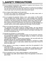
1 SAFETY PRECAUTIONS
A D O not operate the generator near gasoline or gaseous fuel because of the
potential danger of explosion or fire.
Do not fill the fuel tank with fuel while the engine is running. Do not smoke or
use open flame near the fuel tank. Be careful not to spill fuel during refueling.
If fuel is spilt, wipe it off and let dry before starting the engine.
A Do not place inflammables near the generator.
Be careful not to place fuel, matches, gunpowder, oily cloths, straw, trash, or
any other inflammables near the generator.
A D O not operate the generator inside a room, cave, tunnel, or other insufficiently ventilated area. Always operate it in a well-ventilated area, otherwise
the engine may become overheated, and the poisonous carbon monoxide gas
contained in the exhaust gases will endanger human lives. Keep the generator at least 1 meter (3 feet) away from any structure or building during use.
If the generator must be used indoors, the area must be well-ventilated and
extreme caution must be taken regarding the discharge of exhaust gases.
A Do not enclose the generator nor cover it with a box.
The generator has a built-in forced air cooling system, and may become
overheated if it is enclosed. If generator has been covered to protect it from
the weather during non use, be sure to remove it and keep it well away from
the area during generator use.
A Operate the generator on a level surface.
It is not necessary to prepare a special foundation for the generator. However,
the generator will vibrate on an irregular surface, so choose a level place
without surface irregularities.
If the generator is tilted or moved during operation, fuel may spill and/or the
generator may tip over, causing a hazardous situation.
Proper lubrication cannot be expected if the generator is operated on a steep
incline or slope. In such a case, piston seizure may occur even if the oil is
above the upper level.
A P a y attention to the wiring or extension cords from the generator to the
connected device.
If the wire is under the generator or in contact with a vibrating part, it may
break and possibly cause a fire, generator burnout, or electric shock hazard.
Replace damaged or worn cords immediately.
A Do not operate in rain, in wet or damp conditions, or with wet hands.
The operator may suffer severe electric shock if the generator is wet due to
rain or snow.
-1-
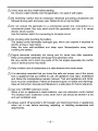
A If wet, wipe and dry it well before starting.
Do not pour water directly over the generator, nor wash it with water.
A Be extremely careful that all necessary electrical grounding procedures are
followed during each and every use. Failure to do so can be fatal.
A D O not contact the generator to a commercial power line. Connection to a
commercial power line may short circuit the generator and ruin it or cause
electric shock hazard.
Use the transfer switch for connecting to domestic circuit.
A No smoking while handling the battery.
The battery emits flammable hydrogen gas, which can explode if exposed to
electric arcing or open flame.
Keep the area well-ventilated and keep open flames/sparks away when
handling the battery.
A E n g i n e becomes extremely hot during and for some time after operation.
Keep combustible materials well away from generator area.
Be very careful not to touch any parts of the hot engine especially the muffler
area or serious burns may result.
/i\Keep children and all bystanders at a safe distance from work areas.
A I t is absolutely essential that you know the safe and proper use of the power
tool or appliance that you intend to use. All opetators must read, understand
and follow the tool/appliance owners manual. Tool and appliance and limitations must be understood. Follow all directions given on labels and warnings.
Keep all instruction manuals and literature in a safe place for future reference.
A Use only “LISTED” extension cords.
When a tool or appliance is used outdoors, use only extension cords marked
“For Outdoor Use”. Extension cords, when not in use should be stored in a dry
and well ventilated area.
A Always switch off generator’s AC breaker and disconnect tools or appliances
when not in use, before servicing, adjusting, or installing accessories and
attachments.
-2-
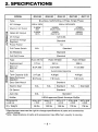
2. SPECIFICATIONS
MODEL
G2410R
1
G3510R
I
G3511R
I
G5710R
I
G5711R
Brushless, Self-Exciting, e-Poles, Single Phase
I
I
AC Voltage
Maximum AC Output
60HZ-120V
I
60HZ-l2OV/240V
2,400W
20A
3.500W
29.2A114.6A
5,700W
47.5A123.8A
12V-8.3A
Condenser Voltage
Standard
J
1.o
N.A.
Standard
AC Breakers
Standard
Full Roll Frame
Standard
Displacement
Maximum
I Electric Start
Auto Idle
N.A.
N.A.
Standard
N.A.
Standaed
Standard
N.A.
Muffler
3imensions
-xWxH
22.4x16.1
x 19.3
24.4x17.7
x21.3
33.7x17.7
X21.3
27.2x18.9
x 23.2
33.7x18.9
x23.2
I r y Weight
99 Ibs
132 Ibs
139 Ibs
172 Ibs
178 Ibs
* Manufacturer reserves the right to change specifications of parts and accessories
without notice.
* Note : Specifications of parts and accessories may differ from country to country.
-3-
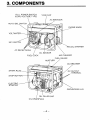
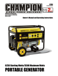
3. COMPONENTS
1
\
ACYEAKER
KE KNOB
ECOIL STARTER
/
FUEL COCK
OILSENSOR
\
AIR CLEANER
FUEL GAUGE
MUFFLER
I
SPARK PLUG
STOP BUTTON
ELECTRIC
STARTER
/
OIL FILLER CAP
OIL DRAINPULG
-4-
/
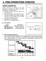
4. PRE-OPERATION CHECKS
CHECK ENGINE OIL.
Before checking or refilling oil, be sure
generator is located on stable and level
surface with engine stopped.
w Remove oil filler cap and check the
engine oil level.
w If oil level is below the lower level line,
refill with suitable oil (see table) to upper
level line. Do not screw in the oil filler
cap when checking oil level.
m Change oil if contaminated.
(See ”How- To” Maintenance.)
Oil capacity
Model
Upper level
.............
0.65 liter(l.38 pints)
~ 2 4 1 0
~
G3510R,G3511R ... 1 .O liter(2.13pints)
G5710R,G5711R
1.2 liter(2.54pints)
m
UPPER LEVEL
Recommended engine oil :
Use class SC (API classification) oil or a higher grade oil according to the table
below. SAE 1OW-30 or 1OW-40 is recommended for general, all-temperature
use. If single viscosity oil is used, select the appropriate viscosity for the
average temperature in your area.
~
Single gradc
Multigrade
Ambient
temperature
I
I
I
-20
-10
0
10
20
I
30
I
40’C
-4
14
32
50
68
86
104‘F
-5-
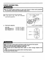
CHECK ENGINE FUEL.
I
Do not refuel while smoking or near open flame or other such potential
fire hazards. Otherwise fire accident may occur.
Check fuel level at fuel level gauge.
If fuel level is low, refill with unleaded
automotive gasoline.
I
/ ,FUEL LEVEL GAUGE’
.
Fuel tank capacity:
-.
,FUEL FILTER SCREEN
G2410R ....*. ....... 2.0 liter (3.17gal.)
G3510R,G351 R
16.6 liter (4.38gal.)
G5710R,G571 R ... 19.0 liter (5.02gal.)
e..
EMPTY
I
Make sure you review each warning in order to prevent fire hazard.
Do not refill tank while engine is running or hot.
Close fuel cock before refueling with fuel.
Be careful not to admit dust, dirt, water or other foreign objects into
fuel.
m Wipe off spilt fuel thoroughly before starting engine.
m Keep open flames away.
-6-
I
l
-
/
w
1
CHECKING COMPONENT PARTS
Check following items before starting engine :
Fuel leakage from fuel hose, etc.
w Bolts and nuts for looseness.
Components for damage or breakage.
Generator not resting on or against any adjacent wiring.
CHECK GENERATOR SURROUNDINGS.
Make sure you review each warning in order to prevent fire hazaed.
m Keep area clear of inflammables or other hazardous materials.
m Keep generator at least 3 feet (lmeter) away from buildings or other
structures.
m Only operate generator in a dry, well ventilated area.
Keep exhaust pipe clear of foreign objects.
Keep generator away from open flame. No smoking!
Keep generator on a stable and level surface.
Do not block generator air vents with paper or other material.
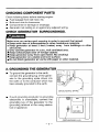
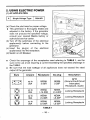
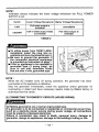
2. GROUNDING THE GENERATOR
To ground the generator to the earth,
connect the grounding lug of the generator to the grounding spike driven into
the earth or to the conductor which has
been already grounded to the earth.
4
GROUNDING SPIKE
If such grounding conductor or grounding
electorode is unavailable, connect the
grounding lug of the generator to the
grounding terminal of the using electric
tool or appliance.
GROUNDING LUG
- 7 -
NOTE :
The National Electrical Code (NEC) requires that all separately derived AC
systems be grounded per Article 250-26. Manufacturer has added a grounding
lug type terminal per Article 250-26 (a) from the noncurrent-carrying metal parts
to the conductor to be grounded. Manufacturer does not supply the required
grounding conductor or grounding electrode because it would be impossible to
cover every exception and all local code requirements. See your local dodes
and the NEC manual for the proper grounding for your application.
- 8 -
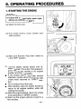
5. OPERATING PROCEDURES
1. STARTING THE ENGINE
ations as outlined on page 5.
(a) Open the fuel cock.
(b) Pull choke knob to close (choke cold
start) position.
(c) Make sure that the “Auto Idle” switch is
in the “OFF” position.
(d) Pull the starter handle slowly until resistance is felt. This is the ”Compression”
point. Return the handle to its original
position and then pull swiftly.
If the engine fails to start after several
attempts, repeat above procedures with
choke knob returned to ”OPEN” position.
Do not fully pull out the rope.
After starting, allow the starter handle to
return to its original position while still
holding the handle.
(e) After the engine started, return the choke
knob gradually to “OPEN” position.
(f) Warm up the engine without a load for a
few minutes.
-9-
Single Voltage Type
A
Style
.
@
G2410R
Ampere
Receptacle
AC plug
Description
up to
20A
NEMA
5-20R
NEMA
5-20P
GFCl
(Ground Fault Circuit
Interrupter)
Receptacle, duplex
up to
20A
NEMA
L14-20R
NEMA
L14-20P
Locking Receptacle
up to
30A
NEMA
L5-30R
NEMA
L5-30P
Locking Receptacle
up to
20A
NEMA
L5-20R
NEMA
L5-20P
Locking Receptacle
.o
- 10
-
Be sure to ground the generator
if the connected electrical
equipment is grounded as instructed on page 7.
If tool or appliance to be operated is grounded type (3 prong
plug), be sure to use only extension cords that are also 3 wire,
grounded type.
NOTE :
When the AC breaker turns off during operation, the generator has been overloaded or the appliance is defective.
Stop the generator immediately, check the appliance and/or generator for
overloading or detect and have repaired as necessary by Makita factory or
authorized service center.
{CAUTION]
The duplex 120V receptacle is protected by a GFCI (Ground Fault Circuit
Interrupter).
GFCI shuts of the output current from the duplex 120V receptacle when a
ground fault occurs in the generator or the appliance.
I
I
m Please note that other receptacles are NOT protected by GFCI..
I
PRECAUTIONS FOR USING THE GFCl RECEPTACLES
After starting the engine, check the GFCl for proper functioning by the following
test procedure.
Push TEST button. The RESET button will pop out exposing the word TRIP.
Power is now off at the outlets protected by the GFCI, indicating that the
device is functioning properly.
H
If TRIP does not appear when testing, do not use the generator. Call a
qualified electrician or have generator repaired at Makita factory or authorized
service center.
To restore power, push RESET button.
- 11 -
If the RESET button pops out during operation, stop the generator immediately and call a qualified electrician to check generator and the
appliances. Failure to do so may result in electric shock hazard or loss of
life.
(d) Checkthe AC breaker is “ON”.
If the breaker is “OFF, set the breaker “ON”.
I 1
I
G3510R,G3511 R
B Dual Voltage Type G5710R,G5711R
I
(a) Select the voltage using the FULL POWER SWITCH in accordance with the
electrical appliance. Refer to TABLE 2.
(b) Operate in the same way as step(a)
through step(d) of single voltage type.
- 12 -
(START
SV I TCH)
NOTE :
Voltmeter always indicates the lower voltage whichever the FULL POWER
SWITCH is set.
I
Switch
120v
120/240v
1 Lower Voltage Receptacle 1 Higher Voltage Receptacle I
Full rated output Is
available
half of rated output watts
is available
unavailable
Full rated output is
available
TABLE 2
8
To utilize power from TWIST LOCKreceptacle, insert the plug into receptacle and turn clockwise to lock it.
Be sure to ground the generator if
the connected electrical equipment
is grounded as instructed on page 7.
If tool or appliance to be operated is
grounded type (3 prong plug), be
sure to use only extension cords
that are also 3 wire, grounded type.
NOTE :
When the AC breaker turns off during operation, the generator has been
overloaded or the appliance is defective.
Stop the generator immediately, check the appliance and/or generator for
overloading or detect and have necessary repairs made by Makita factory or
authorized service center.
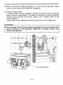
(2) CONNECTING TO DOMESTIC CIRCUITS (HOUSE WIRING)
All Makita generators are a neutral ungrounded type.
If a generator is to be connected to residential or commercial power lines,
such as a stand-by power source during power outage, all connections
must be made by a licensed electrician.
Failure in connection may result in death, personal injury, damage to
generator, damge to appliances, damage to the building’s wiring or fire.
- 13 -
(a) When contnecting a Makita generator to a house wiring, generator output
power must be taken from the 24OV-4P receptacle.
(b) Install a transfer switch.
A transfer switch must be installed to transfer the load from the commercial
power source to the generator. This switch is necessary to prevent accidents
caused by the recovery from power outage. Use a transfer switch of the
correct capacity.
Install transfer switch between the meter and the fusee or AC breaker box.
IF the neutral wire of house wiring is grounded, be sure to ground the
ground terminal of the generator. Otherwise an electric shock may
occur to the operator.
1
- 14 -
I
I
L
switch
__- - -_- - - - - - - - - -- - - - - - - - - -- - - -- -
Generator
*-
4P-Receptacle
(c ) Operating the Generator.
Set the full power switch to 120V/240V side.
Turn the house AC breaker off before starting the generator.
Start the generator and warm it up.
H Turn the house AC breaker on.
H
H
Do not start the generator with electrical appIiance(s)connected and
with their switches on.
Otherwise the appliance(s) may be damaged by the surge voltage at
starting.
- 15
-
(3) DC APPLICATION
DC output capacity of generator is 12V-8.3A (1OOW).
Connect positive (red) terminal on generator to position (+) terminal on battery.
Connect negative (black) terminal on
generator to negative (-) terminal on
battery.
Both AC and DC output can be used at
the same time if the total output is within
rated output of the generator.
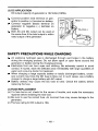
SAFETY PRECAUTIONS WHILE CHARGING
An explosive hydrogen gas is discharged through vent holes in the battery
during the charging process. Do not allow spark or open flame around the
generator or battery during the charging process.
Electrolyte fluid can burn eyes and clothing. Be extremely careful to avoid
contact. If injured, wash the affected area immediately with large quantities of
water and consult a doctor for treatment.
When charging a large capacity battery or totally discharged battery, excessive current may force the DC fuse to blow out. In such cases, use a battery
charger to charge a large battery with AC output.
Battery defects may cause the DC fuse to blow. Check the battery before
replacing the fuse.
(4) FUSE REPLACEMENT
(a) If a fuse burns out, check for the cause of trouble, and make the necessary
repaires before installing the new fuse.
(b) Be sure to use the correct fuse. An incorrect fuse may cause damage to the
generator.
(c) The fuse rating for DC output is 10A.
- 16 -
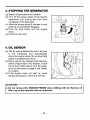
3. STOPPING THE GENERATOR
(a) Switch off generator’s AC breaker.
(b) Turn off the power switch of the electric
equipment and unplug the cord from
receptacle of the generator.
(c) Allow the engine about 3 minutes to cool
down at no-load before stopping.
(d) Push the stop button until the engine
stops.
(e) Close the fuel cock.
4. OIL SENSOR
(a) The oil sensor detects the fall in oil level
in the crankcase and automatically
stops the engine when the oil level falls
below a predetermined level.
(b) When engine has stopped automatically,
switch off generator’s AC breaker, check
the oil level. Refill engine oil to the upper
level as instructed on page 5 and restart
the engine.
(c) If the engine does not start by usual
starting procedures, check the oil level.
CAUTION]
Do not remove OIL SENSOR PROBE when refilling with oil. Remove oil
filler cap on the opposite side of carburetor.
- 17 -
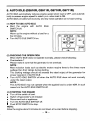
5. AUTO IDLE (GSlOR, G3511R, G571OR, 65711R)
AUTO IDLE automatically reduces engine speed when load is OFF, and automatically increases engine speed to rated r.p.m. when load is ON.
AUTO IDLE provides fuel economy and low noise operation at no-load running.
(1) HOW TO USE AUTO IDLE
I
m
Start the engine with AUTO IDLE
SWITCH off.
NOTE :
Warm up the engine without a load for a
few minutes.
Turn AUTO IDLE SWITCH on.
f
FULL POV
(2) CHECKING THE OPERATION
When AUTO IDLE does not operate normally, please check following :
I Overloadede ?
Please make it sure that the generator is not overload.
NOTE :
Most induction loads such as electric motors require three to five times more
wattage than their ratings during starting.
This starting wattage should not exceed the rated output of the generator for
proper operation of AUTO IDLE.
I Turn AUTO IDLE SWITCH off when the AUTO IDLE does not work normally
under the rated output.
NOTE :
The AUTO IDLE may not operate when the applied load is under 40W. In such
cases turn the AUTO IDLE SWITCH off.
(3) STOPPING THE ENGINE
I Turn off the switch of load.
I Switch off generator’s AC breaker.
I Disconnect tool or appliance.
I Turn the AUTO IDLE SWITCH off.
Push STOP SWITCH to stop.
NOTE :
Allow the engine about 3 minutes to cool down at no-load before stopping.
- 18 -
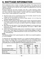
6. WAlTAGE INFORMATION
Some appliances need a "surge" of energy when starting. This means that the
amount of electrical power needed to start the appliance may exceed the amount
needed to maintain its use. See the chart on page 15 for appliances you may use
with this generator.
Electrical appliances and tools normally come with a label indicating voltage,
cycles/Hz, amperage (amps) and electrical power needed to run the appliance or
tool. Check with your nearest dealer or service center with questions regarding
power surge of certain appliances or power tools.
Electrical loads such as incandescent lamps and hot plates require the same
wattage to start as is needed to maintain use.
Loads such as fluorescent and mercury lamps require 1.2 to 2 times the
indicated wattage during start-up.
Electrical motors require a large starting current. Power requirements depend
on the type of motor and its use. Once enough "surge" is attained to start the
motor, the appliance will require only 50% to 30% of the wattage to continue
running.
Most electrical tools require 1.2 to 3 times their wattage for running under load
during use. For example, a 5,000 watt generator can power a 1800 to 4000
watt electrical tool.
Loads such as submersible pumps and air compressors require a very large
force to start. They need 3 to 5 times the normal running wattage in order to
start. For example, a 5,000 watt generator would only be able to drive a 1,000
to 1,700 watt pump.
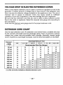
NOTE :
The following wattage chart is general guide only. Refer to your specific appliance
for correct wattagle.
To determine the total wattage required to run a particular electrical appliance or
tool, mutiply the voltage figure of the appliance/tool by the amperage (amps)
figure of same. The voltage and amperage (amps) information can be found on a
name plate which is normally attached to electrical appliances and tools.
Applicable Wattage (W)
Applications
Incandescent lamp, heater
I Fluorescent lamp, mercury lamp I
Electric tool
Pump, compressor
G2410R
G3510R
G3511 R
G5710R
G5711R
60HZ
60HZ
60Hz
3,000
2,000
1,200
I
1,800
4.800
I
2,900
1,200
1,800
2,900
500
700
1,100
I
VOLTAGE DROP IN ELECTRIC EXTENSION CORDS
When a long electric extension cord is used to connect an appliance or tool to the
generator, a certain amount of voltage drop or loss occurs in the extension cord
which recuces the effective voltage available for the appliance or tool. The use of
improper size or gauge of extension cords may cause unsafe or inefficient
operation of your tool or appliance. it may also damage the tool or appliance.
Be sure that any extension cord that you use is rated to allow sufficient current
flow to the motor or appliance. Select the required wire gauge size according to
the chart below.
Chart lists the minimum wire gauge size for the proper extension cord.
EXTENSION CORD CHART
Use the right extension cord. An extension cord should have a suitable wire size
for the overrall cord length and tool amperage rating. This is to prevent a serious
voltage drop, power loss and possible motor damage. Generally, heavier gauge
wire is required as coad lenght increases. Use the recommendations in this table.
Extension
Cord
Length
0.2
2.1 - 3.4
3.5- 5
5.1 - 7
7.1-12
12.1-16
25 feet
18
18
18
18
16
14
50 feet
18
18
18
16
14
12
16
14
12
10
75 feet
18
18
100 feet
18
16
150 feet
16
14
12
200 feet
16
14
12
12
10
300 feet
14
400 feet
12
500 feet
12
600 feet
10
800 feet
-10
I
14
I
12
aNot normally available as flexible extenslon cord
- 20 -
I
10
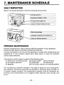
7. MAINTENANCE SCHEDULE
DAILY INSPECTION
Before running the generator, check the following service items:
PERIODIC MAINTENANCE
Periodic maintenance is vital to safe and efficient operation of your generator.
Check the table below for periodic maintenance intervals.
It is also necessary for the user of this generator to conduct the maintenance and
adjustments on the emission-related parts listed below to keep the emission
control system effective.
The emission control system consists of the following parts :
(1) Carburetor and internal parts (2) Choke system (3) Fuel strainer
(4) Air cleaner elements
(5) Intake pipe
(6) Spark plug
(8)
Fuel
hoses,
clamps,
and sealing gaskets
(7) Magneto
The maintenance schedule indicated in the table is based on the normal generator operation. Should the generator be operated in extremely dusty condition or
in heavier loading condition, the maintenance intervals must be shortened depending on the contamination of oil, clogging of filter elements, wear of parts, and
so on.
- 21 -
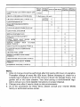
I
CLEAN ENGINE AND CHECK BOLTS AND
NUTS
CHECK AND REFILL ENGINE OIL
8 hours 120 hours
(daily) (weekly)
I
0(Initial
20 hours)
0
0
CLEAN SPARK PLUG
WASH AIR CLEANER ELEMENTS
(* NOTE 2 )
0
CLEAN AND ADJUST SPARK PLUG CAP
REPLACE SPARK PLUG
REPLACE CLEANER ELEMENT
(* NOTE3)
CLEAN VALVE SEAT ALONG WITH
CYLINDER HEAD (* NOTE 3)
REMOVE CARBON FROM CYLINDER
HEAD (* NOTE 3)
I
500hours 1OOOhours
0(daily)
0 (Refill daily to full mark)
CHANGE ENGINE OIL (* NOTE 1 , 2 )
CLEAN FUEL STRAINER
4
1
hours 2oo hou a2monlhs) Q4months'
I
I
I
I
I
I
I
I
l o 1
0
0
0
ADJUST VALVE CLEARANCE (* NOTE 3)
0
CLEAN AND ADJUST CARBURETOR
(* NOTE 3)
0
CHANGE FUEL LINES
0
INSPECT CONTROL PANEL PARTS
(* NOTE 3)
CHECK ROTOR AND STATOR (* NOTE 3)
0
0
REPLACE ENGINE MOUNT RUBBER
(*NOTE 3)
0
OVERHAUL ENGINE (* NOTE 3)
0
NOTE :
1. Initial oil change should be performed after first twenty (20) hours of operation.
Thereafter change oil every fifty (50) hours. Before changing oil, check for a
suitable way to dispose of old oil. Do not pour it down into sewage drains, onto
garden soil or into open streams. Your local zoning or environmental regulations will give you more detailed instructions on proper disposal.
2. Change more often if used in dusty or dirty environments.
3. As to the procedures for these items, please consult your nearest Makita
factory or authorized service center.
- 22 -
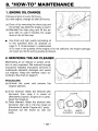
8. "HOW-TO" MAINTENANCE
1. ENGINE OIL CHANGE
Change engine oil every 50 hours.
(for new engine, change oil after 20 hours.)
(a) Drain oil by removing the drain plug and
the oil filler cap while the engine is warm.
(b) Reinstall the drain plug and fill the engine with oil until it reaches the upper
level on the oil filler cap.
Use fresh and high quality lubricating oil
to the specified level as directed on
page 5. If contaminated or deteriorated
oil is used or the quantity of the engine oil is not sufficient, the engine damage
will result and its life will be greatly shortened.
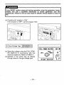
2. SERVICING THE AIR CLEANER
t
Maintaining an air cleaner in proper condition is very important. Dirt induced through
improperly installed, improperly serviced or
inadequate elements damages and wears
out engines. Keep the element clean according to the chart on page 21.
PROCEDURE:
(a) Unhook the cover and remove the
cleaner element.
(b) Inner element: Wash the element with
kemsene, then soak it in mixed oil
(Kerosene (3 parts) : Engine oil (1 part)).
Drain the mixed oil.
(c) Outer element: Wash the element with
kerosene, then dip it into the mixed oil
(Kerosene (3 parts): Engine oil (1 part)).
Squeeze out the mixed oil. (Do not
twist.)
- 23 -
I
1
COVER
OUTER
ELEMENT
INNER
ELEMENT
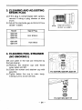
3. CLEANING AND ADJUSTING
SPARK PLUG
(a) If the plug is contaminated with carbon,
remove it using a plug cleaner or wire
brush.
(b) Adjust the electrode gap to 0.6 to 0.7mm
(0.024”- 0.028”)
G241OR
G351OR
G571OR
G5711R
Gap 0.6-0.7”
(0.024“o 0.028”)
NGK BR6HS
NGK B6ES
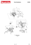
4. CLEANING FUEL STRAINER
(NO SMOKING I)
Dirt and water in the fuel are removed by
the fuel strainer.
(a) Remove the strainer cup and throw
away water and dirt.
(b) Clean the screen and strainer cup with
gasoline.
(c) Tightly fasten the cup to main body,
making sure to avoid fuel leak.
For G241OR, G351OR ,G3511R
For G571OR, G5711R
- 24 -
I
9. PREPARATION FOR STORAGE
The following procedures should be followed prior to storage of your generator for
periods of 6 months or longer.
Drain fuel from fuel tank carefully by disconnecting the fuel line. Gasoline left
in the fuel tank will eventually deteriorate making engine-starting difficult.
Remove the carburetor float chamber and also drain the carburetor.
Change engine oil.
Check for loose bolts and screws, tighten them if necessary.
Clean generator thoroughly with oiled cloth. Spray with preservative if available.
NEVER USE WATER TO CLEAN GENERATOR !
Pull starter handle until resistance is felt, leaving handle in that position.
Store generator in a well ventilated, low humidity area.
- 25 -
10. TROUBLESHOOTING
When generator engine fails to start after several attempts, or if no electricity is
available at the output socket, check the following chart.
If your generator still fails to start or generate electricity, contact your nearest
Makita factory or authorized service center for further information or corrective
procedures.
When Engine Fails to Start :
Check if choke lever is in its proper
position.
Set the choke lever knob to "CLOSE
position.
Check if fuel cock is open.
If closed, open fuel cock.
Check fuel level.
If empty, refill fuel tank making sure
not to overfill.
Check to make sure generator is not
connected to an appliance.
If connected, turn off the power
switch on the connected appliance
and unplug.
Check spark plug for loose spark plug
cap.
If loose, push spark plug cap back
into place.
Check spark plug for contamination.
Remove spark plug and clean electrodes.
When No Electricity Is Generated at Receptacle :
Check to make sure circuit breaker or
no-fuse breaker is in the ON position.
After making sure that the total wattage of the electrical appliance is
within permissible limits and there are
no defects in the appliance, turn the
AC breaker to the "ON"position. If
breakers continue to actuate, consult
your nearest servicing deale: .
Check AC plug for loose connection
Secure connection if necessary.
Check to see if engine starting was
attempted with appliances already
connected to generator and AC
breaker was in the ON position.
Turn off switch on the appliance, turn
AC breaker OFF, and disconnect
cable from receptacle.
Reconnect after generator has been
started properly.
- 26 -
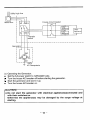
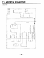
11. WIRING DIAGRAM
1. G2410R
- A
W
I
m
m
LL
z
IA
'0
ICK
IC
z
- 27
-
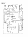
2. G3510R
- - - - 7-N O _ -
__
I1
II
I
I
4) w
I
<
3
0
3
L
3
>
I
I1
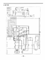
3. G3511R
' 0
I C
I Q
a
~z
w
4. G57'1OR
X
0
m
L
0
LL
t
z
0
U
5. G5711R
I
L
4%
t u
X
0
I
m
0
IU
1
I -
_-
- 31 -
_
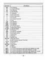
Symbols
SD
I
C.B.
-
rimI
FPSW
MG
IG
MG, SW
E
E
KEY SW
IRECl
I
REC2
Part Name
AC Windina
Auxiliary Winding
DC Winding
Field Winding
Condenser
Idle Control Unit
Diode Stack Assv
Pilot Lamp
DC Output Terminal
Fuse
AC Breaker
AC Breaker
AC Breaker
Full Power Switch
Engine Stop Switch
Auto Idle Switch
Oil Sensor
Oil Sensor Controller
Solid State Ignition
Spark Plug
Magneto
Ignition Coil
Magnetic Switch
Earth Terminal fGround Terminal)
Starting Motor
Solenoid
Kev Switch
Batterv
Voltmeter
AC Output Receptacle (120V-20A) GFCl NEMA No.5-20R
AC Outwt RecePtaclefl20V-30AI NEMA No.L5-30R
AC Output Receptacle (120V/240V-20A) NEMA No.Ll4-20R
AC Output Receptacle (120V-20A) NEMA No.5-20R
- 32 -
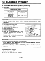
12. ELECTRIC STARTER
1. ELECTRIC STARTER (G3511R, G5711R)
(1) BATTERY
UIR-160 or UIR-200
Capacity
Dimensions
(Maximum)
LxWxH
12V-24AH
1 - -1
7.8“
X
5.2“
X
7.4“
CAUTION]
Do not use a smaller battery which would be overcharged in usual
operation.
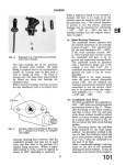
STARTING PROCEDURES
Switch AC breaker OFF.
Turn the “Auto Idle Switch” off.
Open t h e fuel cock.
Choke if engine is cold.
Insert key into key slot and turn it fully
clockwise. Starting motor will turn to
start the engine.
Release key, and it will automatically
returns to “RUN” position.
4CAUTIONI
w Do riot run the starting motor over 5 seconds.
If you failed to start, return key to “STOP” position and wait about 30
seconds, then repeat starting.
H Do not turn the key switch to “START” position while the engine is
running.
(3) STOPPING THE ENGINE
H Switch AC breaker OFF.
H Turn the key switch to “STOP” position.
- 33 -
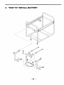
2. “HOW TO” INSTALL BATTERY
-34-
I
MAKITA LIMITED ONE YEAR WARRANTY
Warranty Policy
Every Makita tool is thoroughly inspected and tested before leaving the factory. It is
warranted to be free of defects from workmanship and materials for the period of
ONE YEAR from the date of original purchase. Should any trouble develop during
this one-year period, return the COMPLETE tool, freight prepaid, to one of Makita’s
Factory or Authrorized Service Centers. If inspection shows the trouble is caused by
defective workmanship or material, Makita will repair (or at our option, replace)
without charge.
This Warranty does not apply where:
0 repairs have been made or attempted by others;
there is evidence of normal wear and tear;
The tool has been abused, misused or improperly maintained;
alterations have been made to the tool.
Defects are due to the use of parts, accessories or attachments which are not Makita
genuine products, specifically recommended for use with this tool.
Damage may be caused in transit. (This must be the responsibility of the carrier.)
Claims arise from regulations such as for noise levels, exhaust gas emissions, etc. This
product has been operated for racing purposes or other competitve activities. This
product has been employed for powering equipment that is operated on, in or near
water or explosive atmospheres.
The following parts are expendable (not durable), so warranty does not apply:
Expendable parts including, but not limited to:
Spark plugs, packings, gaskets, rubber materials, washers, nuts, V-belt, engine oil,
grease, paper elements , brushes, mechanical seal, pump impeller and vclute casing.
IN NO EVENT SHALL MAKITA BE LIABLE FOR ANY INDIRECT,
INCIDENTAL OR CONSEQUENTIAL DAMAGES FROM THE SALE OR USE
O F THE PRODUCT. THIS DISCLAIMER APPLIES BOTH DURING AND
AFTER THE TERM O F THIS WARRANTY.
MAKITA DISCLAIMS LIABILITY FOR ANY IMPLIED WARRANTIES,
INCLUDING IMPLIED WARRANTIES O F “MERCHANTABILITY” AND
“FITNESS FOR A SPECIFIC PURPOSE,” AFTER THE ONE-YEAR TERM OF
THIS WARRANTY.
This Warranty gives you specific legal rights. and you may also have other rights
which very from state to state. Some states do not allow the exclusion of limitation of
incidental or consequential damages, so the above limitation or exclusion may not
apply to you. Some states do not allow limitation on how long an implied warranty
lasts. so the above limitation may not apply to you.
Makita Corporation
3-18-8, Sumiyoshi-cho
Anjo, Aichi 446 Japan
PRINTED IN JAPAN