1
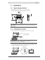
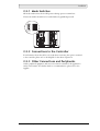
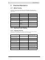
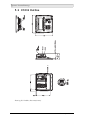
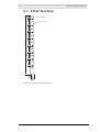
MITSUBISHI ELECTRIC
E1032
Installation manual
MA00816 2006-04
English
Foreword
Installation manual for the E1000 series operator terminals
Foreword
The E1000 operator terminal is developed to satisfy the demands of humanmachine communication. Built-in functions such as displaying and controlling text,
dynamic indication, time channels, alarm and recipe handling are included.
The operator terminal work, for the most part, in an object-oriented way, making it
easy to understand and use. The configuration operation of the terminal is made in
a personal computer, using the configuration tool E-Designer. The project is then
transferred and stored in the operator terminal.
The operator terminal can be connected to many types of automation equipment,
such as PLCs, servos or drives. In this manual the expression “the controller“ is used
as a general term for the connected equipment.
This manual explains how to install the operator terminal. Please refer to the reference manual for further information.
© Mitsubishi Electric, MA00816, 2006-04
The information in this document is subject to change without notice and is provided as available at the time
of printing. The manufacturer reserves the right to change any information without updating this publication.
assumes no responsibility for any errors that may appear in this document.
Read the entire installation manual prior to installing and using this equipment.
Only qualified personnel may install, operate or repair this equipment. The manufacturer is not responsible
for modified, altered or renovated equipment.
Because the equipment has a wide range of applications, users must acquire the appropriate knowledge to use
the equipment properly in their specific applications.
Persons responsible for the application and the equipment must themselves ensure that each application is in
compliance with all relevant requirements, standards and legislation in respect to configuration and safety.
Only parts and accessories manufactured according to specifications set by The manufacturer may be used.
THE MANUFACTURER SHALL NOT BE LIABLE TO ANYONE FOR ANY DIRECT, INDIRECT,
SPECIAL, INCIDENTAL OR CONSEQUENTIAL DAMAGES RESULTING FROM THE
INSTALLATION, USE OR REPAIR OF THIS EQUIPMENT, WHETHER ARISING IN TORT,
CONTRACT, OR OTHERWISE. BUYER'S SOLE REMEDY SHALL BE THE REPAIR,
REPLACEMENT, OR REFUND OF PURCHASE PRICE, AND THE CHOICE OF THE APPLICABLE
REMEDY SHALL BE AT THE SOLE DISCRETION OF THE MANUFACTURER.
Mitsubishi Electric, MA00816
Table of Contents
Table of Contents
1 Safety Precautions.................................................................................
1.1 UL Installation..................................................................................
1.2 General .............................................................................................
1.3 During Use .......................................................................................
1.4 Service and Maintenance...................................................................
1.5 Dismantling and Scrapping...............................................................
2 Installation ...........................................................................................
2.1 Space Requirements ..........................................................................
2.2 Installation Process............................................................................
5
5
5
5
6
6
7
7
7
2.2.1 Mode Switches .................................................................................................. 9
2.2.2 Connections to the Controller ........................................................................... 9
2.2.3 Other Connections and Peripherals ................................................................... 9
3 Technical Data ...................................................................................
4 Chemical Resistance ...........................................................................
4.1 Metal Casing...................................................................................
4.2 Keyboard and Display.....................................................................
11
13
13
13
4.2.1 Display Surface................................................................................................ 13
4.2.2 Autotex F157................................................................................................... 14
5 Operator Terminal Drawings .............................................................
5.1 Communication Ports.....................................................................
5.2 E1032 Outline ................................................................................
5.3 E1032 Text Strip ............................................................................
Mitsubishi Electric, MA00816
17
17
18
19
Table of Contents
Mitsubishi Electric, MA00816
Safety Precautions
1
Safety Precautions
Both the installer and the owner and/or operator of the operator terminal must read
and understand this installation manual.
1.1 UL Installation
Power, input and output (I/O) wiring must be in accordance with Class 1, Division
2 wiring methods (Article 501-4 (b) of the National Electric Code, NFPA 70) and
in accordance with the authority having jurisdiction.
1.2 General
– Only qualified personnel may install or operate the operator terminal.
– The operator terminal must be installed according to the installation instructions.
– The operator terminal is designed for stationary installation on a plane surface,
where the following conditions are fulfilled:
• no high explosive risks
• no strong magnetic fields
• no direct sunlight
• no large, sudden temperature changes
– Never allow fluids, metal filings or wiring debris to enter any openings in the
operator terminal. This may cause fire or electrical shock.
– The operator terminal fulfills the requirements of article 4 of EMC directive
89/336/EEC.
– Storing the operator terminal where the temperature is lower/higher than
recommended in this manual can cause the LCD display liquid to congeal/become
isotopic.
– The LCD display liquid contains a powerful irritant. In case of skin contact, wash
immediately with plenty of water. In case of eye contact, hold the eye open, flush
with plenty of water and get medical attention.
– The supplier is not responsible for modified, altered or reconstructed equipment.
– Use only parts and accessories manufactured according to specifications of the
supplier.
– Peripheral equipment must be appropriate for the application and location.
– The figures in this manual serves an illustrative purpose. Because of the many
variables associated with any particular installation, the supplier cannot assume
responsibility for actual use based on the figures.
– The supplier neither guarantees that the operator terminal is suitable for your
particular application, nor assumes responsibility for your product design,
installation or operation.
1.3 During Use
– Keep the operator terminal clean.
– Emergency stop and other safety functions may not be controlled from the
operator terminal.
– Do not use too much force or sharp objects when touching the keys, display etc.
Mitsubishi Electric, MA00816
5
Safety Precautions
1.4 Service and Maintenance
– Only qualified personnel should carry out repairs.
– The agreed warranty applies.
– Before carrying out any cleaning or maintenance operations, disconnect the
equipment from the electrical supply.
– Clean the display and surrounding front cover with a soft cloth and mild
detergent.
– Replacing the battery incorrectly may result in explosion. Only use batteries
recommended by the supplier.
1.5 Dismantling and Scrapping
– The operator terminal or parts thereof shall be recycled according to local
regulations.
– The following components contain substances that might be hazardous to health
and the environment: lithium battery, electrolytic capacitor and display.
6
Mitsubishi Electric, MA00816
Installation
2
Installation
2.1 Space Requirements
– Installation plate thickness: 1.5 - 7.5 mm (0.06 - 0.3 inch)
– Space requirements when installing the operator terminal:
100 mm
(4.0 inch)
187 mm
(7.36 inch)
100 mm
(4.0 inch)
50 mm
(2.0 inch)
50 mm
(2.0 inch)
100 mm
(4.0 inch)
56.9 mm
(2.24 inch)
202 mm
(7.95 inch)
Caution
The openings on the enclosure are for air convection. Do not cover these
openings.
2.2 Installation Process
1. Unpack and check the delivery. If damage is found, notify the supplier.
Panel cut out 166 x 149 mm
(6.54 x 5.87 inch)
x4
Note:
Place the operator terminal on a stable surface during installation.
Dropping it or letting it fall may cause damage.
2. Place the panel cut out where the operator terminal is to be situated, draw along
the outer sides of the holes and cut according to the markings. If access to the
text strips is needed, add extra space at the left side.
For text strip
14.0 mm
(0.55 inch)
7.0 mm
(0.28 inch)
Mitsubishi Electric, MA00816
7
Installation
3. Secure the operator terminal in position, using all the fastening holes and the
provided brackets and screws:
x4
0.5 - 1.0 Nm
4. Connect the cables in the specified order.
A
B
Caution
Ensure that the operator terminal and the controller system have the
same electrical grounding (reference voltage level), otherwise errors
in communication may occur.
Use an M5 screw and a grounding conductor (as short as possible)
with a cross-section of minimum 2.5 mm2.
C
D
Caution
- Use only shielded communication cables.
- Separate high voltage cables from signal and supply cables.
Caution
- The operator terminal must be brought to ambient temperature
before it is started up. If condensation forms, ensure that the
operator terminal is dry before connecting it to the power outlet.
- Ensure that the voltage and polarity of the power source is correct.
B
Power
Controller
RS422/
RS485
RS232
24V DC
24V DC
C
D
A
Ethernet
5. Carefully remove the laminated film over the operator terminal display, to avoid
static electricity that could damage the terminal.
8
Mitsubishi Electric, MA00816
Installation
2.2.1 Mode Switches
All mode switches must be in OFF position during operator terminal use.
The mode switches should not be touched unless by qualified personell.
ON DIP
1 2 3 4
ON DIP
1 2 3 4
2.2.2 Connections to the Controller
For information about the cables to be used when connecting the operator terminal
to the controller, please refer to the help file for the driver in question.
2.2.3 Other Connections and Peripherals
Cables, peripheral equipment and accessories must be suitable for the application
and its environment. For further details or recommendations, please refer to the
supplier.
Mitsubishi Electric, MA00816
9
Installation
10
Mitsubishi Electric, MA00816
Technical Data
3
Technical Data
Parameter
E1032
Front panel, W x H x D 202 x 187 x 6 mm
Mounting depth
56.9 mm (156.9 mm including clearance)
Front panel seal
IP 66
Rear panel seal
IP 20
Keyboard material
Membrane switch keyboard with metal domes. Overlay film
of Autotex F157 * with print on reverse side. 1 million
operations.
Reverse side material
Powder-coated aluminum
Weight
0.875 kg
Serial port RS422/
RS485
25-pin D-sub contact, chassis-mounted female with
standard locking screws 4-40 UNC.
Serial port RS232C
9-pin D-sub contact, male with standard locking screws 4-40
UNC.
Ethernet
Shielded RJ 45
USB
Host type A (USB 1.1), max output current 500 mA
Flash memory for
application
12 MB (incl. fonts)
Real time clock
±20 PPM + error because of ambient temperature and supply
voltage.
Total max error: 1 min/month at 25 °C
Minimum life of the real time clock battery: 3 years
Temperature coefficient: 0.004 ppm/°C2
Power consumption at
rated voltage
Normal: 0.15 A
Maximum: 0.35 A
Display
FSTN-LCD. 240 x 64 pixels, monocrome transflective.
LED backlight lifetime at the ambient temperature of
+25 °C: >50,000 h.
Active area of display,
WxH
127.0 x 33.8 mm
Fuse
Internal DC fuse, 2.0 AT, 5 x 20 mm
Power supply
+24V DC (20 - 30V DC). 3-pin jack connection block.
CE: The power supply must conform with the requirements
for SELV or PELV according to IEC 950 or IEC 742.
UL: The power supply must conform with the requirements
for class II power supplies.
Ambient temperature
Vertical installation: 0 ° to +50 °C
Horizontal installation: 0 ° to +40 °C
Storage temperature
-20 ° to +70 °C
Relative humidity
5 - 85 % non-condensed
EMC tests on the
operator terminal
The operator terminal conforms with the essential protection
requirements in article 4 of the directive 89/336/EEC. Noise
tested according to EN61000-6-3 emission and EN61000-6-2
immunity.
UL, cUL approvals
(when product or
packing is marked)
UL 1604 Class I, Div 2 / UL 508 / UL 50 4x indoor use only
DNV
Ceritfication in progress
NEMA
4x indoor use only
* See section Chemical Resistance for more information.
Mitsubishi Electric, MA00816
11
Technical Data
12
Mitsubishi Electric, MA00816
Chemical Resistance
4
Chemical Resistance
4.1 Metal Casing
The frame and casing material is powder-coated aluminum. This powder paint
withstands exposure of up to 24 hours duration to the following chemicals without
visible change:
Ammonia 25%
Isopropyl alcohol
Nitric acid 3%
De-ionized water
Tap water
Chlorhydric acid 10%
Butanol
Cooling liquid 50%
Washer fluid 33%
Citric acid 10%
Ligroin
Sulphuric acid 20%
Diesel
Cooking oil
Turpentine
Ethanol 99.5% denaturated
Lactic acid 10%
Urea saturated
FAM-Normal petrol
Sodium di-chromate
saturated
Hydroperoxide 3%
Alcohol 95%
Caustic soda 5%
Acetic acid 10%
Phosphoric acid 43%
Sodium hypochlorite
solution
Alu-cleaner
Glycol
Sodium carbonate 10%
-
Industrial petrol
Sodium chloride 20%
-
4.2 Keyboard and Display
4.2.1 Display Surface
The display surface on the operator terminal withstands exposure of more than 24
hours duration to the following chemicals without visible change:
Acetic acid <5%
Dichloromethane
Nitric acid
(specific gravity 1.42)
Glacial acetic acid
(specific gravity 1.05)
Di-ethylether
Nitric acid <40%
Ethyl acetate
Di-isobutylene
Oleic acid
Acetone
Di-methyl hormamide
Olive oil
Aqueous ammonia
(specific gravity 0.9)
Ethyl alcohol <95%
Pure water
Aqueous ammonia <10%
2-ethyl hexoic acid
Seawater
Benzene
Hydrochloric acid <35%
Sodium carbonate <20%
Carbon tetrachloride
Hydrogen peroxide <28%
Sodium hypochlorite <10%
Caustic soda <48%
Isopropyl alcohol
Sulfuric acid
(specific gravity 1.84)
Citric acid
Kerosene
Sulfuric acid <30%
Cotton seed oil
Methy alcohol
Toluene
Mitsubishi Electric, MA00816
13
Chemical Resistance
4.2.2 Autotex F157
Autotex F157 covers the membrane keyboard.
Solvent Resistance
Autotex F157 withstands exposure of more than 24 hours duration under DIN 42
115 Part 2 to the following chemicals without visible change:
Potassium ferrocyanide/
ferricyanide
Sodium hypchlorite <20%
(bleach)
1.1.1. Trichloroethane
(Genklene)
Cyclohexanol
Acetaldehyde
Ethylacetate
Diacetone alcohol
Aliphatic hydrocarbons
Diethyl ether
Glycol
Toluene
N-Butyl acetate
Isopropanol
Xylene
Amylacetate
Glycerine
White spirit
Butycellosolve
Methanol
Fromic acid <50%
Ether
Triacetin
Acetic acid <50%
MIBK
Dowanol DRM/PM
Phosphoric acid <30%
Cutting oil
Acetone
Hydrochloric acid <36%
Potassium carbonate
Metyl ethyl ketone
Nitric acid <10%
Washing powders
Dioxan
Trichloracetic acid <50%
Fabric conditioner
Cyclohexanone
Sulphuric acid <10%
Ferric chloride
Ethanol
Formaldehyde 37% - 42%
Ferrous chlorid
Isophorone
Potassium hydroxide <30%
Dibutyl Phthalate
Ammonia <40%
Linseed oil
Dioctyl Phthalate
Caustic soda <40%
Paraffin oil
Sodium carbonate
Hydrogen peroxide <25%
Blown castor oil
Petrol
Alkalicarbonate
Silicone oil
Teepol
Bichromate
Turpentine substitute
Water
Diesel oil
Univeral brake fluid
Sea water
Acetonitrile
Decon
-
Sodium bisulphate
Aviation fuel
-
Autotex withstands DIN 42 115 Part 2 exposure of up to 1 hour duration to glacial
acetic acid without visible change.
Autotex is not resistant to high pressure steam at over 100 °C or the following
chemicals:
Concentrated mineral acids
Benzyl alcohol
Concentrated caustic solution
Mehylene chloride
Autotex withstands 24 hours exposure to the following reagents at 50 °C without
visible staining:
14
Top Job
Grape Juice
Ariel
Ajax
Jet Dry
Milk
Persil
Vim
Gumption
Coffee
Wisk
Domestos
Fantastic
-
Lenor
Vortex
Formula 409
-
Downey
Windex
Mitsubishi Electric, MA00816
Chemical Resistance
Very slight discoloration was noted under critical viewing conditions with the
following materials:
Tomato juice
Tomato ketchup
Lemon juice
Mustard
Outdoor Use
In common with all polyester based films, Autotex F157 is not suitable for use in
conditions of long term exposure to direct sunlight.
Mitsubishi Electric, MA00816
15
Chemical Resistance
16
Mitsubishi Electric, MA00816
Operator Terminal Drawings
5
Operator Terminal Drawings
5.1 Communication Ports
RS-232
RS-422
RS-485
RS-422/485
USB
Ethernet
Drawing No. S-05005, Date 2004-10-27
Mitsubishi Electric, MA00816
17
Operator Terminal Drawings
5.2 E1032 Outline
Drawing No. P-06629, Date 2005-10-05
18
Mitsubishi Electric, MA00816
Operator Terminal Drawings
10,75
5.3 E1032 Text Strip
19,75
Text max 17,0x8,0
19,75
20,5
20,5
179
20,5
20,5
20,5
Text max 18,5x8,0
4,5
9
Drawing No. S-06627, Date 2005-07-19
Mitsubishi Electric, MA00816
19
MITSUBISHI ELECTRIC
Mitsubishi Electric Automation, Inc.
500 Corporate Woods Parkway
Vernon Hills, IL 60061, USA
Mitsubishi Electric Europe B.V.
Gothaer Strasse 8
D-40880 Ratingen, Germany