1
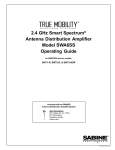
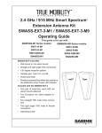
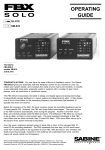
Operating Guide
SWM4000 Series
Quick Start Guide ........................................................................................................... 2
Components .................................................................................................................. 3
Receiver ......................................................................................................................... 4-5
Handheld Transmitter .................................................................................................... 6
Beltpack Transmitter ....................................................................................................... 7
Operating Instructions ................................................................................................... 8
Setting up your System .................................................................................................. 9
Appendix A Manual Programming ................................................................................. 10
Appendix B Frequencies and Groups ............................................................................ 11
Appendix C Rack-Mounting Receivers ........................................................................... 11
Appendix D Tips for Improving System Performance .................................................... 12
Appendix D Troubleshooting .......................................................................................... 12
© 2011 Sabine, Inc.
Appendix E Specifications .............................................................................................. 13
1
Sabine SWM4000 Smart Spectrum® Wireless
LIT-SWM4000-OG-EN-101215.indd
Quick Start Guide for SWM4000 WIRELESS SYSTEMS
Setting up the SWM4000 Receivers.
1. Plug the PSU power supply into the wall socket and receiver and power on the unit.
2. Push the MENU button until the words “Auto Select” appear in the LCD (SW40-RH). Or, the word “SCAN” for the SW40-RF
3. Push the SET button. The SW40-RH or SW40-RF will set itself to a clear channel and display the channel on the receiver LCD.
4. Turn on a transmitter (leave the other transmitters turned off). Aim the transmitter’s IR sensor about 8 inches from the receiver’s IR
scanner and press the receiver’s S.O. (SYNC) button for several seconds while the receiver programs the transmitter. When the group
and channel numbers on the transmitter matches the receiver, the system is ready to operate. The RF LED should be fully lit when you
are standing close.
Expose the IR port to the receiver, press S.O. (SYNC)
SW40-RF
SW40-RH
© 2011 Sabine, Inc.
5. Speak, sing or play into the transmitter to adjust the volume control so that the A.F. LEDs generally light under normal performance
conditions. The volume should be adjusted so that the top A.F. LED only lights momentarily with the loudest inputs. You will hear a
harsh clipping sound if the top LED stays lit under normal levels.
6. Adjusting the squelch. The squelch controls the maximum distance between the transmitter and receiver. It is set to maximum range
at the factory and should be kept there in most cases.
For Multiple Systems
• Repeat steps 1 – 6 if you wish to add more systems. IMPORTANT: Make sure to keep the transmitters that have been set up
turned on so that new receivers will know those channels are busy.
• See Appendix A for manually selecting the frequencies of your system.
• Be sure that only one transmitter’s IR port is exposed when setting up a system.
Sabine SWM4000 Smart Spectrum® Wireless
2
Components
SW40-RH Half-Rack receivers include:
• Power Supply
• Dipole antennas (1 pair)
• Rack Mount kit:
Short rack ear
Long rack ear
Link bar to mount a second SW40-RH receiver
8 rack screws
• Extension cables and connectors for front-mounting antennas
• 1/4 inch patch cable (not shown)
• Rubber feet
• Operating guide
SW40-R modular receivers include:
• Module Frame with 2 or 4 modules
• Dipole antennas (1 pair)
• Power Supply
• Rack Ears and hardware
• Rubber feet
• Operating guide
SW40-H Handheld transmitters include:
• Microphone and transmitter
• Mic holder
• AA batteries (1 pair)
SCALE
6.000
SW45-T Beltpack transmitters include:
• Beltpack transmitter
• AA batteries (1 pair)
© 2011 Sabine, Inc.
SW45-T
SWASS-EXT 3
SWT10L-CB-TA4
or
SWT41L-CB-TA4
SWT74W-OSB-TA4
SWT74W-ODB-TA4
3
Optional:
• Extention antennas.
• lavalier microphone
• single-ear microphone
• double-ear microphone
See www.Sabine.com for details.
Sabine SWM4000 Smart Spectrum® Wireless
LIT-SWM4000-OG-EN-101215.indd
SW40-RF-Module Receiver Details
Front Panel
R1
Power on/off
POWER
SW40-RF
SCALE
Module B
Module A
R1
1.000
Module D
Module C
R2
R5
R6
R9
R10
R12
Module Front
R2
R3
R4
R5
R6
R7
Volume (Gain)
Squelch
RF signal
Active antenna
I.R. sensor
Group selection
R8
R9
R10
R11
R12
R13
VOL
Channel number
Lock all controls
Set
Menu
Sync
Audio signal
TRUE DIVERSITY
RECEIVER
A
UHF
SET
ANT
I.R.
B
GROUP
CHANNEL
02 04
SW40-RM
S.Q.
R3
SYNC
MENU
RF
R4
AF
R7
R8
R11
Back Panel
R14
R15
R16
R15
R16
© 2011 Sabine, Inc.
R15
Antenna B
XLR output jack for module D (balanced)
1/4” jack output for module D (unbalanced)
XLR output jack for module C (balanced)
1/4” jack output for module C (unbalanced)
XLR output jack for module B (balanced)
R14
R15
R16
R15
Sabine SWM4000 Smart Spectrum® Wireless
R16
R15
R16
R15
R16
R15
R16
R17
R18
R19
R16
4
1/4” jack output for module B (unbalanced)
XLR output jack for module A (balanced)
1/4” jack output for module A (unbalanced)
Mixed output for all modules (unbalanced)
PSU power jack
Antenna A
R17
R18
R19
R13
SW40-RH 1/2-Rack Receiver Details
R1
R2
R4
R6
R10
R11
R12
R13
R20
Power On/Off switch - Push up to turn on, push down to turn off.
Volume control. The volume control dial should generally be left in the clockwise position.
Turning the dial counter-clockwise decreases receiver output level.
RF LED - Indicates strength of incoming RF signal.
Smart option - Press to initiate IR connection between receiver and transmitter.
Set switch - Press to select the currently displayed menu option.
Menu switch - Press to scroll through menu options.
Infrared (IR) port - Broadcasts IR signal to transmitter to synchronize frequencies..
Audio LED - Indicates strength of incoming audio signal.
LCD display
SW40-RH
SET
MENU
R4
R10
R20
R13
R11
R2
R6
R12
R1
LCD display
R5
R7
R8
R9
R21
R22
R23
R24
Antenna status
Group selection
Manual channel selection
Lock/unlock receiver settings
Transmitter Battery status
Automatic frequency selection
Display frequency
Incompatable frequency
R5
INCOMPATIBLE
R21
R3
R14
R15
R16
R18
© 2011 Sabine, Inc.
R19
R27
Squelch
Antenna jack B
XLR output jack
1/4 jack output jack
AC adapter jack
Antenna jack A
Adapter cord tie-off
R24
R22
R7
R8
R9
R23
SW40-RH
R14
R16
R15
5
R3
R27
R18
R19
Sabine SWM4000 Smart Spectrum® Wireless
LIT-SWM4000-OG-EN-101215.indd
SW40-H Handheld Transmitter Controls
To Open: Unscrew lower portion of microphone.
Pull down as you continue to turn the housing.
To Close: Turn the housing and push up until it
meets the threads, then screw on.
H1
H2
H3
H5
H6
H4
H5
H6
H7
H8
Select Button
Up Button
Down Button
Programmable Control of External Switch
Infrared Port
Transmitter LCD Screen
External Switch
Transmitter controls and battery compartments
H7
B
A
E
Transmitter LCD screen
H4
A Group Number
B Channel Number
H2
C Antenna Indicator - Low output
D Antenna Indicator - High output
E Battery life Indicator
H8
D
C
H1
H3
Transmitter Controls
DTM2
Programming the Handheld Transmitter
A Group/Channel: Press the Select button to enter Edit Mode, and repeat until the
SCALE
1.000
GROUP indicator flashes. In this mode, the Up/Down buttons will adjust Group selection. Choose your group, then press the select button until the CHANNEL indicator
flashes. In this mode, the Up/Down buttons will adjust Transmission Channel.
C D RF Output: Press the Select button to enter Edit Mode, and repeat until the antenna
indicators flashes. The small antenna symbol indicates low output (useful if there are
many transmitters clustered together) and the large antenna symbol indicates high
output (good for larger spaces). Press the up or down buttons to add or subtract the
high-level output symbol.
H4 Internal Control of External Switch: The recessed transmitter controls include a
© 2011 Sabine, Inc.
3-position switch, which in turn determines how the transmitter’s external two-position
switch behaves. From left-to-right, the 3 positions of the internal switch correspond
to the following external switch operations. NOTE: The antenna symbol blinks when
the transmitter is not muted.
- ON-OFF: In the off position the transmitter is turned off. When you turn it on
there is a short boot-up period before the mic turns on.
- ON-MUTE: In the off position the audio is muted, but the transmitter is still
on. Use this when you need the audio to come on instantly when turning on the
microphone.
- ON-ON: In both switch positions the mic is on. In essence you are disabling
the external switch, and leaving the mic on at all times. This is useful if you are
working with talent that might accidentally turn off the mic.
E Battery Life Indicator: The battery symbol shows the battery level. Typical battery
life is 8 hours.
Sabine SWM4000 Smart Spectrum® Wireless
6
SW45-T Beltpack Transmitter
Antenna (replaceable)
Audio gain adjustment switch
B3 IR port - Receives infrared beam to synchronize frequencies.
When using multiple systems, only one transmitter IR port should be exposed at a time.
B4 LCD screen
B5 Battery cover (slide both clips down to open)
B6 TA4-F microphone input jack
B7 On-off switch
B8 On-off / on-mute / on-on switch (located under the case, above the battery compartment).
Use a pencil to select option. Switch is hidden to protect from accidental nudge.
B9 Up
B10 Down
B11 Select
B1
B1
B2
B2
B3
B4
SW45-T
B5
Wearing the Beltpack Transmitter
B6
Clip the transmitter to a belt until the belt is pressed
against the base of the clip.
B7
B9
B8
Controls
Changing Batteries
Expected life for an Alkaline battery is approximately 8 hours.
Change batteries when the battery bar in LCD display is empty, as shown below:
B10
B11
B1
B7
Top view
B2
B6
Programming the Beltpack Transmitter
© 2011 Sabine, Inc.
1. With the power on, press and hold the select button until the GROUP and CHANNEL
displays begin to alternate.
2. To change the group setting, release the select button while GROUP is flashing.
(While GROUP is flashing, pressing up or down increases/decreases the group setting by one.)
3. Press select button to switch between GROUP and CHANNEL settings.
Indicates charge remaining in transmitter batteries.
7
Sabine SWM4000 Smart Spectrum® Wireless
LIT-SWM4000-OG-EN-101215.indd
Operating Instructions
Congratulations on purchasing your Sabine SWM4000 Series Wireless Microphone System. This system
is specially designed to provide you with excellent audio quality, ease of use, and reliability.
Frequency Bands The SW4000 series is available in several frequency bands to accommodate various
local governmental regulations throughout the world. The frequency band of your system is represented
by the numbers appended to the part number. For example, the SW40-RM3-U-915 operates in the 915
MHz band while the SW40-RM3-E-860 operates in the 860 MHz band.
The band recommended for the US and Canada, along with Central and South American is the 915 Mhz
band. This band is immune to interference from analog and digital TV, mobile or smart phones, and most
WIFI devices. It operates with up to 8 concurrent users in the same location.
Contact your local distributor to determine the best band for your location outside of the Americas. Or, visit
www.sabine.com for the most current information.
Installing the SW4000 system in your sound system.
Antennas. Antennas pick up the signal from the transmitters and transfers it to the receiver where it converted to an audio signal. A pair of SWAANT dipole antennas are included with your system. Antennas are
like the “eyes” of the system. You will hear dropouts if the antennas cannot “see” the transmitter. Antennas
cannot “see” through steel or concrete. If your antennas are mounted on the back of the receiver, rotate
the receiver body around so that the antennas are in the line of sight of the transmitter.
A receiver mounted in a rack must use the back-to-front cables and have the antennas mounted in the line
of sight of the transmitter on the front of the rack. Also, dipole antennas should be orientated to the 11:00
and 2:00 positions for the best reception.
If the antennas are blocked or shadowed, you should replace the SWAANT antennas with Sabine’s
SWASS-EXT-3 external antennas. Make sure you specify the frequency band of your system when
you order.
Audio Connections Your receiver has both a balanced XLR and unbalanced ¼-inch audio jacks on the
back panel to connect the receiver to your mixer or powered speaker. Use the balanced jack whenever
possible.
Channel Selection Follow the steps on the next page to quickly find interference-free channels.
© 2011 Sabine, Inc.
Note: transmitting devices such as cellular phones and two-way radios may interfere with
wireless audio transmissions. Keep your transmitters and receivers away from these and
other potential sources of interference.
Sabine SWM4000 Smart Spectrum® Wireless
8
Setting up your Wireless Systems
1. Plug the PSU power supply into the wall socket and receiver.
2. (SW40-RH) Push the MENU button until the words Auto Select appear in the LCD. (SW40-RF) Push the MENU button until the words
scan appear in the LCD.
3. Push the SET button. The SW40-RH or SW-40-RF will set itself to a clear channel and display the channel on the receiver LCD.
4. Turn on a transmitter (leave the other transmitters turned off). Aim the transmitter’s IR sensor about 8 inches from the receiver’s IR
scanner and press the receiver’s S.O. (SYNC) button for several seconds while the receiver programs the transmitter. When the group
and channel numbers on the transmitter matches the receiver, the system is ready to operate. When you are standing close, the RF
LED ladder on the SW40-RH should be fully lit or, on the SW40-RF, the RF LED bar will be lit.
Expose the transmitter IR port to the receiver (within 8 inches), press S.O. (SYNC)
SW40-R
SW40-RH
© 2011 Sabine, Inc.
5. Speak, sing or play into the transmitter to adjust the volume control so that the A.F. LEDs generally light under normal performance
conditions. The volume should be adjusted so that the top A.F. LED only lights momentarily with the loudest inputs. You will hear a
harsh clipping sound if the top LED stays lit under normal levels.
6. Adjusting the squelch. The squelch controls the maximum distance between the transmitter and receiver. It is set to maximum range
at the factory and should be kept there in most cases.
For Multiple Systems
• Repeat steps 1 – 6 if you wish to add more systems. IMPORTANT: Make sure to keep the transmitters that have been set up
turned on so that new receivers will know those channel are busy.
• See Appendix A (pg.10) for manually selecting the frequencies of your system.
• Be sure that only one transmitter’s IR port is exposed when setting up a system.
9
Sabine SWM4000 Smart Spectrum® Wireless
LIT-SWM4000-OG-EN-101215.indd
Appendix A
Manual Programming
R7
Allows manual selection of a frequency group. Pressing SET increases the group number by one. When the correct
frequency is displayed press S.O. (SYNC). For best results when operating multiple systems, set all systems to a single
group; then set each system to a unique channel within that group.
R8
Allows manual selection of a frequency channel. Pressing SET increases the channel number by one. When the
correct frequency is displayed press S.O. (SYNC).
*
R23
Display the current frequency in MHz. Press again to display group and channel.
R9
Hold down the SET key and press MENU to lock or unlock the receiver. Locking prevent the current receiver settings
from changing.
R5
Indicates RF activity. Only one antenna is active at any one time.
R21
Indicates a low transmitter battery charge.
R26
The INCOMPATIBLE warning indicates that the receiver and transmitter are set to incompatible frequency bands.
Contact your retailer for assistance.
Any option displayed on screen will generally time out after five seconds
R2
R5
R6
R9
R10
R12
SW40-RF Module Front
R2
R3
R4
R5
R6
R7
Volume (Gain)
Squelch
RF signal
Active antenna
I.R. sensor
Group selection
R8
R9
R10
R11
R12
R13
VOL
Channel number
Lock all controls
Set
Menu
Sync
Audio signal
R7
R8
R9
R21
R22
R23
© 2011 Sabine, Inc.
R24
Antenna status
Group selection
Manual channel selection
Lock/unlock receiver settings
Transmitter Battery status
Automatic frequency selection
Display frequency
Incompatable frequency
*
I.R.
B
GROUP
SET
CHANNEL
02 04
SYNC
MENU
SW40-RM
S.Q.
R3
RF
R4
AF
R7
R8
R11
R5
R13
R24
INCOMPATIBLE
R21
Available only on the SW40-RH
Sabine SWM4000 Smart Spectrum® Wireless
UHF
ANT
SW40-RH LCD display
R5
TRUE DIVERSITY
RECEIVER
A
10
R22
R7
R8
R23
R9
Appendix B
Frequencies and Groups
FREQUENCY BAND SELECTION
Most countries closely regulate radio frequency devices to limit RF (radio frequency) interference. Many countries are in
the process of changing their regulations in order to accomodate requirements for DTV braodcasts and smart phones.
SWM4000 systems are available in several frequency ranges. Contact your local retailer to determine the bands that
are suitable in your area. Sabine is making new frequency bands available as the regulations evolve. The most current
information can be found at www.Sabine.com.
The following bands are available at the time this manual was printed:
902-928 MHz - For the Americas and the Pacific Rim (These frequencies are expected to remain license free and relatively free of interference for the foreseable future.)
710-740 MHz - For use in Europe.
606-630 MHz - For use in the UK.
SWM4000 systems typically provide predefined frequency groups and channels. All microphones in a system should be
set to individual channels within a sinlge group to reduce the chance of interference. DO NOT SET TWO TRANSMITTERS TO THE SAME GROUP AND CHANNEL.
Up to 8 individual transmitter/receiver systems may be used simultaniously in the same venue. It is possible to operate
up to 20 systems simultaneously.
© 2011 Sabine, Inc.
Appendix C
Rack-Mounting SW40-RH Receivers
11
Sabine SWM4000 Smart Spectrum® Wireless
LIT-SWM4000-OG-EN-101215.indd
© 2011 Sabine, Inc.
Appendix D
Sabine SWM4000 Smart Spectrum® Wireless
12
© 2011 Sabine, Inc.
Appendix E
Specifications
SW40 Receiver
SW40-H Handheld Transmitter
Operating Range Under Typical Conditions
100m (300 ft)
Note: actual range depends on RF signal absorption,
reflection, and interference
Audio Frequency Response (+/- 2 dB)
Maximum: 20 kHz
Minimum: 50 Hz
(Overall system frequency depends on microphone element.)
Total Harmonic Distortion (ref. +/- 30 kHz deviation, 400Hz tone)
0.5%, typical
Dynamic Range
>100 dB A-weighted
Operating Temperature Range
-18ºC (0~F) to +57ºC (+135ºF)
Note: battery characteristics may limit this range
Dimensions
SW40-R4: 44 mm H x 420 mm W x 207 mm D
SW40-RH: 41 mm H x 205 mm W x 158 mm D
Weight
960 g
Housing
Galvanized steel
Audio Output Level(ref.+/- 30kHz deviation
with 400Hz tone)
XLR connector (into 600 Q load): -30dBV
1/4 inch connector (into 3000 Q Ioad):-9dBV
Output Impedance
XLR connector: 200
1/4 inch connector: 1k
XLR output
Impedance balanced
Pin 1: Ground (cable shield)
Pin 2: Audio
Pin 3: No Audio
Sensitivity
-105 dBm for 12 dB SINAD, typical
Image Rejection
>70 dB, typical
Power Requirements
22V dc at 400mA, supplied by external
power supply
RF Transmitter Output
30 mW maximum (dependent on applicable
country regulations)
Dimensions (including EM-l1S cartridge)
270 mm x 52 mm dia.
Weight
250 g without batteries
Housing
Metal case with handeling-noise suppression and soft
touch, non slip finish
Power Requirements
2 “AA” size alkaline or rechargeable batteries
Battery Life
>8 hours (alkaline)
SW45-T Beltpack Transmitter
Gain Adjustment Range
30 dB
Input Impedance
500 K
RF Transmitter Output
30 mW maximum (dependent on applicable country
regulations)
Dimensions
97 mm H x 66 mm W x 20 min D
Weight
105 g without batteries
Housing
Molded ABS case
Power Requirements
2”AA’ size alkaline or rechargeable batteries
Battery Life
>8 hours (alkaline)
13
Sabine SWM4000 Smart Spectrum® Wireless
LIT-SWM4000-OG-EN-101215.indd
Cautions & Warranty
CAUTION!
EXPOSURE TO EXTREMELY HIGH NOISE LEVELS MAY CAUSE A PERMANENT
HEARING LOSS. INDIVIDUALS VARY CONSIDERABLY IN SUSCEPTIBILITY TO NOISE
INDUCED HEARING LOSS, BUT NEARLY EVERYONE WILL LOSE SOME HEARING IF
EXPOSED TO SUFFICIENTLY INTENSE NOISE FOR A SUFFICIENT TIME. THE U.S.
GOVERNMENT’S OCCUPATIONAL SAFETY AND HEALTH ADMINISTRATION (OSHA)
HAS SPECIFIED THE FOLLOWING PERMISSIBLE NOISE LEVEL EXPOSURES:
DURATION/DAY
IN HOURS SLOW
RESPONSE
8
6
4
3
SOUND
LEVEL
IN dBA
DURATION/DAY
IN HOURS SLOW
RESPONSE
90
92
95
97
2
1-1½
1
½
SOUND
LEVEL
IN dBA
100
102
105
110
ACCORDING TO OSHA, ANY EXPOSURE IN EXCESS OF THE ABOVE PERMISSIBLE
LIMITS COULD RESULT IN HEARING LOSS. EAR PLUGS OR PROTECTORS IN
THE EAR CANALS OR OVER THE EARS MUST BE WORN WHEN OPERATING THIS
DEVICE IN ORDER TO PREVENT A PERMANENT HEARING LOSS, IF EXPOSURE
IS IN EXCESS OF THE LIMITS AS SET FORTH ABOVE. TO ENSURE AGAINST
POTENTIALLY DANGEROUS EXPOSURE TO HIGH SOUND PRESSURE LEVELS, IT
IS RECOMMENDED THAT ALL PERSONS EXPOSED TO EQUIPMENT CAPABLE OF
PRODUCING HIGH SOUND PRESSURE LEVELS SUCH AS THIS DEVICE BE PROTECTED BY HEARING PROTECTORS WHILE THIS UNIT IS IN OPERATION.
FBX and FBX Feedback Exterminator® are registered trademarks
of Sabine, Inc., and are the brand names of its line of automatic
feedback controllers. Covered by U.S. Patent No. 5,245,665,
Australian Patent No. 653,736, Canadian Patent No. 2,066,624-2,
German Patent No. 69118486.0, and U.K. Patent No. 0486679.
Other patents pending. True Mobility® is a trademark of Sabine,
Inc. Copyright 2004 Sabine, Inc. All rights reserved.
THIS LIMITED WARRANTY VALID ONLY WHEN PURCHASED AND
REGISTERED IN THE UNITED STATES OR CANADA. ALL EXPORTED
PRODUCTS ARE SUBJECT TO WARRANTY AND SERVICES TO BE
SPECIFIED AND PROVIDED BY THE AUTHORIZED DISTRIBUTOR
FOR EACH COUNTRY.
Ces clauses de garantie ne sont vaiables qu’aux Etats-Unis et au Canada.
Dans tous les autres pays, les clauses de garantie et de maintenance
sont fixees par le distributeur national et assuree par lui selon la legislation en vigueur.
Diese Garantie ist nur in den USA and Kanada gultig. Alle Export-Produkte
sind der Garantie und dem Service des Importeurs des jewelligen Landes
untervorfen.
Esta garantia es valida solamente cuando el producto es comprado en E.U.
continentales o en Canada. Todos los productos que sean comprados en
el extranjero, estan sujetos a las garantias y servicio que cada distribuidor
autorizado determine y otrezca en los diferentes paises.
ONE-YEAR LIMITED WARRANTY/REMEDY
SABINE, INC. (“SABINE”) warrants this product to be free from defects
in material and workmanship for a period of one (1) year from date of
purchase PROVIDED, however, that this limited warranty is extended only
to the original retail purchaser and is subject to the conditions, exclusions
and limitations hereinafter set forth:
CONDITIONS, EXCLUSIONS AND LIMITATIONS OF
LIMITED WARRANTIES
© 2011 Sabine, Inc.
1. These limited warranties shall be void and of no effect if:
a. The first purchase of the product is for the purpose of resale; or
b. The original retail purchase is not made from an AUTHORIZED
SABINE DEALER; or
c. The product has been damaged by accident or unreasonable use,
neglect, improper service or maintenance, or other causes not arising
out of defects in material or workmanship; or
d. The serial number affixed to the product is altered, defaced or removed; or
e. The power supply grounding pin is removed or otherwise defeated. In
the event of a defect in material and/or workmanship covered by this
limited warranty, Sabine will repair the defect in material or workmanship or replace the product, at Sabine’s option; and provided, however,
that, in any case, all costs of shipping, if necessary, are paid by you,
the purchaser.
2. NiMH batteries included with the original purchase are warranted for
ninety (90) days from date of purchase.
THE WARRANTY IS NOT VALID UNLESS REGISTERED ONLINE (www.
sabine.com) AND RECIEVED BY SABINE WITHIN FOURTEEN (14) DAYS
FROM THE DATE OF YOUR PURCHASE.
In order to obtain service under these warranties, you must:
a. Bring the defective item to any Authorized SABINE DEALER and present the ORIGINAL PROOF OF PURCHASE supplied to you by the
AUTHORIZED SABINE DEALER in connection with your purchase from
Sabine SWM4000 Smart Spectrum® Wireless
them of this product. If the DEALER is unable to provide the necessary warranty service, you will be directed to the nearest other SABINE
AUTHORIZED DEALER which can provide such service.
OR:
b. Ship the defective item, prepaid, to:
SABINE, INC.
13301 NW US HIGHWAY 441
ALACHUA, FL 32615-8544
Include therewith a complete, detailed description of the problem, together
with a legible copy of the original PROOF OF PURCHASE and a complete
return address. Upon Sabine’s receipt of these items:
If the defect is remedial under the limited warranties and the other terms
and conditions expressed have been complied with, Sabine will provide
the necessary warranty service to repair or replace the product and will
return it, FREIGHT COLLECT, to you, the purchaser.
Sabine’s liability to the purchaser for damages from any cause whatsoever
and regardless of the form of action, including negligence, is limited to the
actual damages up to the greater of $500.00 or an amount equal to the
purchase price of the product that caused the damage or that is the subject
of or is directly related to the cause of action. Such purchase price will be
that in effect for the specific product when the cause of action arose. This
limitation of liability will not apply to claims for personal injury or damage
to real property or tangible personal property allegedly caused by Sabine’s
negligence. Sabine does not assume liability for personal injury or property
damage arising out of or caused by a non-Sabine alteration or attachment,
nor does Sabine assume any responsibility for damage to interconnected
non-Sabine equipment that may result from the normal functioning and
maintenance of the Sabine equipment.
UNDER NO CIRCUMSTANCES WILL SABINE BE LIABLE FOR ANY LOST PROFITS, LOST
SAVINGS, ANY INCIDENTAL DAMAGES OR ANY CONSEQUENTIAL DAMAGES ARISING
OUT OF THE USE OR INABILITY TO USE THE PRODUCT, EVEN IF SABINE HAS BEEN
ADVISED OF THE POSSIBILITY OF SUCH DAMAGES.
THESE LIMITED WARRANTIES ARE IN LIEU OF ANY AND ALL WARRANTIES, EXPRESS
OR IMPLIED, INCLUDING BUT NOT LIMITED TO, THE IMPLIED WARRANTIES OF MERCHANTABILITY AND FITNESS FOR A PARTICULAR USE; PROVIDED, HOWEVER, THAT
IF THE OTHER TERMS AND CONDITIONS NECESSARY TO THE EXISTENCE OF THE
EXPRESS LIMITED WARRANTIES, AS HEREINABOVE STATED, HAVE BEEN COMPLIED
WITH, IMPLIED WARRANTIES ARE NOT DISCLAIMED DURING THE APPLICABLE ONEYEAR PERIOD FROM DATE OF PURCHASE OF THIS PRODUCT.
SOME STATES DO NOT ALLOW LIMITATION ON HOW LONG AN IMPLIED WARRANTY
LASTS, OR THE EXCLUSION OR LIMITATION OF INCIDENTAL OR CONSEQUENTIAL
DAMAGES, SO THE ABOVE LIMITATIONS OR EXCLUSIONS MAY NOT APPLY TO YOU.
THESE LIMITED WARRANTIES GIVE YOU SPECIFIC LEGAL RIGHTS, AND YOU MAY
ALSO HAVE OTHER RIGHTS WHICH MAY VARY FROM STATE TO STATE.
THESE LIMITED WARRANTIES ARE THE ONLY EXPRESS WARRANTIES ON THIS PRODUCT, AND NO OTHER STATEMENT, REPRESENTATION, WARRANTY OR AGREEMENT
BY ANY PERSON SHALL BE VALID OR BINDING UPON SABINE.
In the event of any modification or disclaimer of express or implied warranties, or any limitation of remedies, contained herein conflicts with
applicable law, then such modification, disclaimer or limitation, as the
case may be, shall be deemed to be modified to the extent necessary to
comply with such law.
Your remedies for breach of these warranties are limited to those remedies
provided herein, and Sabine gives this limited warranty only with respect
to equipment purchased in the United States of America.
INSTRUCTIONS-WARRANTY REGISTRATION:
1. Register online at www.Sabine.com
a.Keep the PROOF OF PURCHASE. In the event warranty service
is required during the warranty period, you will need this document.
There will be no identification card issued by Sabine, Inc.
2. IMPORTANCE OF WARRANTY REGISTRATION AND NOTIFICATION
OF CHANGES OF EMAIL ADDRESS:
a.Completion of WARRANTY REGISTRATION - Should notification
become necessary for any condition that may require correction, the
ONLINE REGISTRATION will help ensure that you are contacted and
properly notified.
b.Notice of email address changes - If you change email address shown
on the WARRANTY REGISTRATION, you should notify Sabine of the
change so as to facilitate your receipt of any bulletins or other forms
of notification which may become necessary in connection with any
condition that may require dissemination of information or correction.
3. You may contact Sabine directly by telephoning (386) 418-2000.
4. Please have the Sabine product name and serial number available when
communicating with Sabine Customer Service.
Manufactured by:
14
Sabine, Inc.
13301 NW US Highway 441
Alachua, Florida 32615-8544 USA
Phone: +USA (386) 418-2000
Fax: +USA (386) 418-2001
© 2011 Sabine, Inc.
NOTES:
15
Sabine SWM4000 Smart Spectrum® Wireless
LIT-SWM4000-OG-EN-101215.indd
03/01/2010
W I R E L E S S SYS T E M S
Sabine, Inc.
13301 NW US Highway 441
Alachua, Florida 32615-8544 USA
Phone: (386) 418-2000
Fax: (386) 418-2001
www.Sabine.com