1
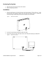
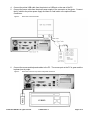
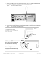
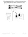
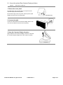
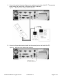
1800 Series POS Bundle
1800 POS Bundle Installation Guide
Thank you for selecting UTC RETAIL’s innovative 1800 Series Point of Sale bundle solution!
This guide is designed to help you efficiently assemble the 1800 Series POS Bundle System.
© 2008 UTC RETAIL. All rights reserved.
11692014 Rev C
Page 1 of 12
1800 Series POS Bundle System Installation Guide
This guide was prepared by UTC RETAIL to assist personnel with the installation of the bundle
components. All attempts have been made to ensure that the information presented in this manual is
correct. No liability, expressed or implied, will be assumed by UTC RETAIL or affiliates for damage
resulting from the use of this information.
All rights reserved. No part of this document may be reproduced, stored in a retrieval system, or
transmitted in any form or by any means, electronic or mechanical, including photocopying, recording, or
otherwise, without the prior written permission of UTC RETAIL.
If a unit needs to be shipped to UTC RETAIL for repairs, please return it in the original packaging material
and shipping container. If you have questions, please call UTC RETAIL’s Technical Support at
1.800.349.0546.
The 1800 Series Touch Screen POS Workstation complies with UL60950 requirements. This equipment
has been tested and found to comply with the limits for a Class “A” digital device, pursuant to Part 15 of the
FCC Rules. These limits are designed to provide reasonable protection against harmful interference when
the equipment is operated in a commercial environment. This equipment generates, uses, and can radiate
radio frequency energy and, if not installed and used in accordance with the instruction manual, may cause
harmful interference to radio communications. Operation of this equipment in a residential area is likely to
cause harmful interference, in which case the user will be required to correct the interference at his/her own
expense.
Safety Precautions
DANGER: High Voltage
This unit contains high voltage. There is a risk of electrical shock if the case is opened. If service is required, contact
an authorized service agent or UTC RETAIL (UTC).
WARNING: CMOS Battery Damage
Replace your system's battery only with CR-2032 (or equivalent) 3V Lithium-Ion coin cell battery to avoid risk of
personal injury or physical damage to your equipment. Always dispose of used batteries according to local ordinance,
where applicable. Any damage due to not following this warning will void your motherboard's manufacturer warranty.
WARNING: Access to Internal Components
All access to internal components of the Series 1800 unit is restricted to Authorized Service Personnel only. Opening
the case or service by anyone else will automatically void the warranty on this product.
WARNING: Connect AC Power Cable last
To avoid accidental power-up during installation, connect the AC Power Cable last.
WARNING: Electrical Shock
Use caution when connecting cables. To avoid electric shock, do not connect safety extra-low voltage (SELV) circuits
to telephone-network voltage (TNV) circuits. Local Area Network (LAN) ports contain SELV circuits, and telephone
ports contain TNV circuits. Some LAN ports and some telephone ports use RJ-45 connectors.
CAUTION:
Damage to the unit components may occur if AC power is not removed from the product prior to attaching any
accessories.
© 2008 UTC RETAIL. All rights reserved.
11692014 Rev C
Page 2 of 12
Table of Contents
1800 Series POS Bundle System Installation Guide ................................................................2
Product Information ..................................................................................................................4
Un-boxing the System...............................................................................................................5
Installation.................................................................................................................................5
Powering On Your 1800 Series POS Bundle System .............................................................11
Troubleshooting Procedures...................................................................................................12
© 2008 UTC RETAIL. All rights reserved.
11692014 Rev C
Page 3 of 12
Product Information
You will find the following components inside the 1800 Series POS Bundle System Box:
•
Safety Sheet
•
1800 Series POS All-in-One unit (Touch Screen PC / logic device)
•
A/C power cord for logic device
•
Cash drawer
•
Barcode scanner
•
POS receipt printer
•
Keyboard
•
Mouse
Note: The following optional items may or may not be present depending on the configuration
purchased and may be shipped in a separate box.
•
Magnetic Stripe Reader (MSR)
•
Payment Terminal - Pin Pad device, power supply & cables
•
Payment Terminal - Signature Capture device, power supply & cables
•
Rear Customer Display
•
Inventory Scanner
•
AC Power Conditioner
•
Traffic Counter and Door Sensor
•
Label / Ticket Printer
© 2008 UTC RETAIL. All rights reserved.
11692014 Rev C
Page 4 of 12
Un-boxing the System
1.
Open the point of sale box and remove the contents.
2.
Remove all packing materials.
Installation
1.
Orient the cash drawer on its back side on your cash wrap (counter). Remove the keys. Locate
the cash drawer cable package, labeled ‘APG cash drawer 320 Multipro cable kit’. Connect the
end with the larger modular plug into the jack on the base of the cash drawer.
Figure 1:
Bottom View of Drawer
2.
Lay down the cash drawer and place the cable to the side.
3.
Connect the other end of the cash drawer cable to the POS printer drawer port, labeled ‘DK’.
Figure 2:
Bottom View of Drawer
© 2008 UTC RETAIL. All rights reserved.
11692014 Rev C
Page 5 of 12
4.
Connect the printer USB cable from the printer to a USB port on the rear of the PC.
5.
Connect the power cable from the printer power supply to the connector on the printer. Connect
the AC cable to the printer power supply and then to a wall outlet or the optional Power
Conditioner.
Figure 3:
6.
Rear View of PC and Printer
Connect the mouse and keyboard cables to the PC. The mouse port on the PC is green and the
keyboard port is purple.
Figure 4:
Rear View of PC and Top views of keyboard and mouse
© 2008 UTC RETAIL. All rights reserved.
11692014 Rev C
Page 6 of 12
7.
Connect the USB connector end of the Barcode Scanner cable to a USB port on the back of the
PC. Connect the other end into the jack on the barcode scanner handle.
Figure 5:
8.
Rear View of PC, Scanner connection
Connect the optional MSR (Magnetic Stripe Reader) assembly to the 1800 Series unit as follows:
Figure 6:
Back View of 1800 Unit and MSR Assembly
Main Unit
1. Connect the USB cable
Insert the USB connector into the USB port at
the side of the main unit.
USB Port
To MSR Unit
2. Position the MSR
MSR Unit
Align the MSR unit with the guide rails on the
main unit and slide it into position, making
sure the entire USB cable is covered by the
MSR housing.
3. Insert and tighten screws
Insert the two screws provided with the MSR
unit, and tighten to secure the MSR housing
to the main unit.
© 2008 UTC RETAIL. All rights reserved.
Insert screws
11692014 Rev C
USB
Page 7 of 12
9.
Connect the optional Payment Terminal (Pin Pad or Signature Capture device) to a Serial Port on
the back of the PC. For instructions on the Signature Capture device cable connections, refer to
the install guide included with the terminal. Plug the AC power adapter into a wall outlet or the
optional Power Conditioner.
Figure 7:
Rear View of PC, Payment Terminal connection
© 2008 UTC RETAIL. All rights reserved.
11692014 Rev C
Page 8 of 12
10. Connect the optional Rear Customer Display as follows:
Figure 8:
Rear View of 1800 Unit
1. Remove the cover panel
The 1800 Series main unit ships with a cover panel over the
Customer Display attachment position.
Lift the bottom edge of the cover panel, and then pull the panel
straight up to expose the connecting cable.
Rear Panel Cover
2. Connect the cable
Connect the cable between the Customer Display and the main
unit. Tuck the cable and connector into the opening.
3. Snap the Customer Display into place
Align the bottom of the Customer Display in the track. Then slide
the Customer Display straight down until it snaps into position.
© 2008 UTC RETAIL. All rights reserved.
11692014 Rev C
Page 9 of 12
11. Connect the optional Inventory Scanner to a serial port on the back of the PC. Then plug the
power supply into a wall outlet or the optional Power Conditioner.
Figure 9:
Rear View of PC, Inventory Scanner connection
12. Connect a site provided network cable into the network jack on the back of the PC.
Figure 10:
Rear View of PC, Network cable connection
© 2008 UTC RETAIL. All rights reserved.
11692014 Rev C
Page 10 of 12
13. Plug the PC power cord into the receptacle on the rear of the PC and then into the wall outlet or
optional Power Conditioner.
Figure 11:
Rear View of PC, Power cord connection
Powering On Your 1800 Series POS Bundle System
1.
Remove the plastic protective sheets from the LCD Monitor and the optional rear customer display.
2.
Turn on the ATX PC power by depressing the on/off switch located on the lower front right-hand side of
the unit.
3.
To activate the printer, turn on the printer rocker switch located on the front of the printer.
You have completed the installation of UTC RETAIL’s 1800 Series Bundled Point of Sale System. If you
experience problems with any of the components of the 1800 Series Bundled POS System, see the
“Troubleshooting Procedures” section below.
© 2008 UTC RETAIL. All rights reserved.
11692014 Rev C
Page 11 of 12
Troubleshooting Procedures
The following table presents symptoms and solutions for problems potentially encountered when installing
the 1800 Series Bundled POS System components.
Symptom
Touch screen accuracy
is off
The printer does not
have power.
The printer has power
but the system does
not boot to Windows.
A keyboard error
message displays
when you boot the
1800 Series POS unit.
The rear customer
display does not have
power.
Solutions
•
Recalibrate the touch screen using the calibration utility.
•
Check to see if the printer power cable is properly connected to the
printer.
•
Make sure that the printer power switch is ON.
•
Push the ATX power button in the front of the logic unit located on the
lower front right hand side of the unit.
•
Check to see if the keyboard cable is properly connected to the
keyboard. Make sure that the keyboard cable is connected to the
keyboard port (purple) on the logic unit, not to the mouse port (green).
•
Make sure the customer display is plugged in to connector provided
on back of unit behind the panel cover.
Please call UTC RETAIL’s Technical Support at 800.349.0546, if you have any problems not addressed in
the Troubleshooting Procedures or have questions about other sections of this documentation.
© 2008 UTC RETAIL. All rights reserved.
11692014 Rev C
Page 12 of 12


![Notice_d``installation_Solar_Set[1] (3811 ko) - Domo](http://vs1.manualzilla.com/store/data/006325956_1-4c510b243905a1d5ce505f51f928dca7-150x150.png)