1
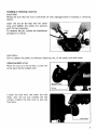
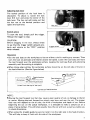
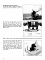
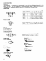
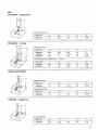
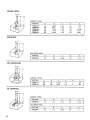
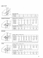
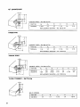
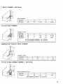
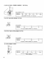
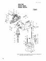
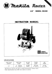
Router
MODEL 3620
MODEL 3620A
Equipped with electric brake
INSTRUCTION MANUAL
DOUBLE
I
SPECIFICATIONS
Collet chuck capacity
1/4"
I
Main body stroke
3 5 m m (1-3/8"1
I
No
I
';k"p"dyed Overall length
24,000
21 1 m m 18-5/16")
I
A1'ION
N e t weight
2.4 k g 15.3 Ibs)
IMPORTANT
SAFETY INSTRUCTIONS
(For All Tools)
WARNING: WHEN USING ELECTRIC TOOLS, BASIC SAFETY PRECAUTIONS SHOULD ALWAYS BE FOLLOWED TO
REDUCE THE RISK OF FIRE, ELECTRIC SHOCK, AND PERSONAL INJURY, INCLUDING THE FOLLOWING:
READ ALL INSTRUCTIONS.
1. KEEP WORK AREA CLEAN. Cluttered areas and benches invite injuries.
2. CONSIDER WORK AREA ENVIRONMENT. Don't use power tools in damp
or wet locations. Keep work area well lit. Don't expose power tools t o rain.
Don't use tool in presence of flammable liquids or gases.
3. KEEP CHILDREN AWAY. All visitors should be kept away from work area.
Don't let visitors contact tool or extension cord.
4.STORE IDLE TOOLS. When not in use, tools should be stored in dry, and high
or locked-up place - out of reach of children.
5. DON'T FORCE TOOL. It will do the job better and safer at the rate for which
it was intended.
6. USE RIGHT TOOL. Don't force small tool or attachment t o do the job of a
heavy-duty tool. Don't use tool for purpose not intended.
7 . DRESS PROPERLY. Don't wear loose clothing or jewelry. They can be caught
in moving parts. Rubber gloves and non-skid footwear are recommended
when working outdoors. Wear protective hair covering t o contain long hair.
8. USE SAFETY GLASSES. Also use face or dust mask if cutting operation is
dusty.
9. DON'T ABUSE CORD. Never carry tool by cord or yank it t o disconnect from
receptacle. Keep cord from heat, oil, and sharp edges.
IO. SECURE
WORK. Use clamps or a vise t o hold work. It's safer than using
your hand and it frees both hands t o operate tool.
1 1 . DON'T OVERREACH. Keep proper footing and balance at all times.
12. MAINTAIN TOOLS WITH CARE. Keep tools sharp and clean for better and
safer performance. Follow instructions for lubricating and changing accessories. Inspect tool cords periodically and if damaged, have repaired by authorized service facility. Inspect extension cords periodically and replace if
damaged. Keep handles dry, clean, and free from oil and grease.
13. DISCONNECT TOOLS. When not in use, before servicing, and when changing accessories, such as blades, bits, cutters.
2
14. REMOVE ADJUSTING KEYS AND WRENCHES. Form habit of checking t o
see that keys and adjusting wrenches are removed from tool before turning
it on.
15. AVOID UNINTENTIONAL STARTING. Don't carry plugged-in tool w i t h finger
on switch. Be sure switch is OFF when plugging in.
16. OUTDOOR USE EXTENSION CORDS. When tool is used outdoors, use only
extension cords intended for use outdoors and so marked.
17. STAY ALERT. Watch what you are doing, use common sense. Don't operate
tool when you are tired.
18. CHECK DAMAGED PARTS. Before further use of the tool, a guard or other
part that is damaged should be carefully checked t o determine that it will
operate properly and perform its intended function. Check for alignment of
moving parts, binding of moving parts, breakage of parts, mounting, and
any other conditions that may affect its operation. A guard or other part
that is damaged should be properly repaired or replaced by an authorized
service center unless otherwise indicated elsewhere in this instruction
manual. Have defective switches replaced by authorized service center. Don't
use tool if switch does not turn it on and off.
19. GUARD AGAINST ELECTRIC SHOCK. Prevent body contact w i t h grounded
surfaces. For example; pipes, radiators, ranges, refrigerator enclosures.
20. REPLACEMENT PARTS. When servicing, use only identical replacement parts.
21. POLARIZED PLUGS. To reduce the risk of electric shock, this equipment has
a polarized plug (one blade is wider than the other). This plug will fit in a
polarized outlet only one way. If the plug does not fit fully in the outlet,
reverse the plug. If it still does not fit, contact a qualified electrician to install
the proper outlet. Do not change the plug in any way.
VOLTAGE WARNING: Before connecting the tool t o a power source (receptacle,
outlet, etc.) be sure the voltage supplied is the same as that specified on the
nameplate of the tool. A power source w i t h voltage greater than that specified
for the tool can result in SERIOUS INJURY t o the user - as well as damage t o
the tool. If in doubt, DO NOT PLUG IN THE TOOL. Using a power source w i t h
voltage less than the nameplate rating is harmful t o the motor.
3
ADDITIONAL SAFETY RULES
1. Handle the bits very carefully.
2. Check the bit carefully for cracks or damage before operation. Replace
cracked or damaged bit immediately.
3. Avoid cutting nails. Inspect for and remove all nails from the workpiece before operation.
4. Hold the tool firmly w i t h both hands.
5. Keep hands away from rotating parts.
6. Make sure the bit is not contacting the workpiece before the switch is turned
on.
7. Before using the tool on an actual workpiece, let it run for a while. Watch
for vibration or wobbling that could indicate improperly installed bit.
8. Be careful of the bit rotating direction and the feed direction. (cf. P. 7 )
9. Do not leave the tool running. Operate the tool only when hand-held.
IO. Always switch off and wait for the bit t o come t o a complete stop before
removing the tool from workpiece.
11. Do not touch the bit immediately after operation; it may be extremely hot
and could burn your skin.
12. Keep the bit retracted so as not t o protrude from the tool base except during actual operation.
SAVE THESE INSTRUCTIONS.
4
Installing or removing router bit
CAUTION :
Always be sure that the tool i s switched off and unplugged before installing or removing
the bit.
Insert the bit all the way into the collet
cone and tighten the collet nut securely
with the two wrenches.
To remove the bit, follow the installation
procedure in reverse.
Tighten
t
CAUTION :
Do not tighten the collet nut without inserting a bit, or the collet cone will break.
Adjusting depth of cut
Place the tool on a flat surface. Loosen the
screw securing the stopper pole.
Loosen the lock lever and lower the tool
body until the bit just touches the flat
surface. Tighten the lock lever to lock the
tool body.
5
Next, lower the stopper pole until it makes
contact with the adjusting hex bolt. Align
the depth pointer with the "0" graduation.
Raise the stopper pole until the desired depth of cut i s obtained. The depth of cut is
indicated on the scale (1 mm or 1/16" per graduation) by the depth pointer. Then tighten
the screw to secure the stopper pole.
Now, your predetermined depth of cut can be obtained by loosening the lock lever and
then lowering the tool body until the stopper pole makes contact with the adjusting hex
bolt.
CAUTION :
Since excessive cutting may cause overload of the motor' or difficulty in controlling the
tool, the depth of cut should not be more than (5/8")a t a pass when cutting grooves with
a (1/4") diameter bit.
[Note: When cutting grooves with an (3/4") diameter bit, the depth of cut should not be
more than (1/4") a t a pass.] When you wish to cut grooves more than (5/8")deep with a
(1/4") diameter bit or more than (1/4") deep with an (3/4") diameter bit, make several
passes with progressively deeper bit settings.
Stopper block
The stopper block has three adjusting hex bolts which raise or lower 0.8 mm (about
1/32") per turn. You can easily obtain three different depths of cut using these adjusting
hex bolts without readjusting the stopper pole.
Adjust the lowest hex bolt to obtain the deepest depth of cut, following the method of
"Adjusting depth of cut". Adjust the two remaining hex bolts to obtain shallower depths
of cut. The differences in height of these hex bolts are equal to the differences in depths
of cut.
To adjust the hex bolts, first loosen the hex nuts on the hex bolts with the wrench and
then turn the hex bolts. After obtaining the desired position, tighten the hex nuts while
holding the hex bolts in the desired position.
The stopper block is also convenient for making three passes with progressively deeper bit
settings when cutting deep grooves.
6
Adjusting lock lever
The locked position of the lock lever is
adjustable. To adjust it, loosen the lock
lever 3/4 turn and press the center of the
lock lever. The hex nut will come out. Set
the hex nut to the desired position and
tighen the lock lever.
Switch action
To start the tool, simply pull the trigger.
Release the trigger to stop.
CAUTION:
Before plugging in the tool, always check
to see that the trigger switch actuates properly and returns to the "OFF" position
when released.
Operation
*Set the tool base on the workpiece to be cut without the bit making any contact. Then
turn the tool on and wait until the bit attains full speed. Lower the tool body and move
the tool forward over the workpiece surface, keeping the tool base flush and advancing
smoothly until the cutting is complete.
When doing edge cutting, the workpiece surface should be on the left side of the bit in
the feed direction. (See the figure below)
Feed direction
///,'/!3it
revolving direction
(View from the top of the tool)
~..
r__-,
7,
v
Correct bit feed direction
NOTE :
Moving the tool forward too fast may cause a poor quality of cut, or damage to the bit
or motor. Moving the tool forward too slowly may burn and mar the cut. The proper
feed rate will depend on the bit size, the kind of workpiece and depth of cut. Before
beginning the cut on the actual workpiece, it is advisable to make a sample cut on a
piece of scrap lumber. This will show exactly how the cut will look as well as enable you
to check dimensions.
*When using the straight guide, be sure to install it on the right side in the feed direction.
This will help to keep it flush with the side of the workpiece.
7
Straight guide (optional accessory)
The straight guide i s effectively used for
straight cuts when chamfering or grooving.
To install the straight guide, insert the
guide bars into the holes in the tool base.
Adjust the distance between the bit and
the straight guide. At the desired distance,
tighten the wing bolts to secure the straight
guide in place.
1
J
When cutting, move the tool with the straight guide flush with the side of the workpiece.
If the distance (A) between the side of the
workpiece and the cutting position is too
wide for the straight guide, or if the side
of the workpiece i s not straight, the
straight guide cannot be used. In this case,
firmly clamp a straight board to the workpiece and use it as a guide against the
router base. Feed the tool in the direction
of the arrow.
8
Templet guide (optional accessory)
The templet guide provides a sleeve through
which the bit passes, allowing use of the
router with templet patterns.
To install the templet guide, loosen the
screws on the tool base, insert the templet
guide and then tighten the screws.
Screw
1
Base plate
I
-
Templet guide
Secure the templet to the workpiece. Place
the tool on the templet and move the tool
with the templet guide sliding along the
side of the templet.
MA1NTENANCE
CAUTION :
Always be sure that the tool is switched off and unplugged before attempting to perform
inspection or maintenance.
To maintain product SAFETY and RELlABl LITY, repairs, carbon brush inspection
and replacement, any other maintenance or adjustment should be performed by Makita
Authorized or Factory Service Centers, always using Makita replacement parts.
9
ACCESSORIES
CAUTION :
These accessories or attachments are recommended for use with your Makita tool specified in this
manual. The use of any bther accessories or attachments might present a risk of injury t o persons.
The accessories or attachments should be used only in the proper and intended manner.
Templet guide
part
No
Templei guide
A
10
7 7 113164"l
11
13
~-
164379 4
1647756
1647764
-
-
1648354
-
1643930
164470-8
e
C
9 5 !3/8"l
11 5 123164'1
9 123164")
11 17116'1
13 133164")
11 17116"l
12 7 1112")
13 133164"l
16
14.5 137164')
16 1518")
13 133164"l
20
18 145164")
20 125132"l
13 133164")
27
13 l33/64"l
24 115116"l
27 11-1/16")
163080-8
23
25 163/64"l
29 11-9/64")
15 119132")
164471-6
30
27 I1 1/16")
30 I1 3/16',)
13 133164")
1644724
40
37 11-29/64")
40 11-37/64")
11 5 129/64'l
Part No.
TamplBt guide
321812.1
25
~
~.
Templet guide 25
~
I
I
A
122.6 157/64"l
I
I
8
25.4 11")
Lock nut
(for templet guide 25)
Part No. 252627-4
Templet guide adapter
(for templet guide 25)
L
A
4
~.
Part No.
321492-3
1
1
A
30 11-3/16')
I
lmml
B
35 (1-3/8"1
1 B - J
Straight guide
Part No. 164834-6
Wrench 22
Part No. 781011-1
Wrench 13
Part No. 781006-4
Collet cone
Size : 1/4"
Part No. 763637- 1
Trimmer guide assembly
Part No. 122385-5
10
Wrench 8
P
I
1
C
7 (9132'1
1
,, ... . .,
C
11 17/16'1
Bits
STRAIGHT
- Single Flute
HIGH SPEED STEEL
I
I
PARTNO.
A
B
C
D
E
7332326A
118
5/16
i-iia
114
1.518
PART NO.
A
B
C
D
E
733003-2A
733003-4A
733003.8~
3/16
1I 4
5/16
7/16
314
1
1.318
1-3/16
1-1/ a
114
1I 4
114
2
2-118
2-3/16
1
I
~
~
~~
HINGE MORTISING
CARBIDE TIPPED
PART NO.
A
8
C
D
E
733006-9A
112
112
1-1/16
1I 4
1-13/16
HIGH SPEED STEEL
PART NO.
A
B
C
D
E
733235-0A
1/2
112
314
114
1-15/16
VEINING -Single Flute
i D k
SOLID CARBIDE
PART NO.
A
B
C
D
E
733007-8A
3/16
7/32
1.114
1I 4
1-112
11
ROUND NOSE
%ICARBIDE TIPPED
PART NO.
733008-2A
7330084A
733008-6A
733008-8A
733009-0A
1-1I4
1-114
1-114
1-114
1-1/4
15/32
9116
11/16
11/16
13/16
318
112
518
3/4
1-718
1I 4
114
1/4
2-3116
2-114
2-3/8
CORE BOX
=/
HIGH SPEED STEEL
PART
NO.
733238-2A
A
B
C
D
E
1I4
114
1-3/16
114
1-112
~~
VEE GROOVING
CARBIDE TIPPED
PART NO.
A
B
C
D
E
E
733009-2A
733009-4A
318
518
112
314
1-3/16
15116
114
1/4
2
9 0"
90"
2
14" DOVETAIL
CARBIDE TIPPED
PART NO.
A
B
C
D
E
733009-6A
112
112
1-114
1I4
1-718
~
~~
HIGH SPEED STEEL
12
PART NO.
A
B
C
D
E
733239-6A
1I 2
1I2
1-318
1I 4
2
I
PANEL PILOT
HIGH SPEED STEEL
C~~~~~
ROUNDING
PART NO.
A
B
C
D
E
733236-0A
114
3/4
1
1/4
2-7/16
CARBIDE TIPPED - Ball Bearing Pilot
733120-0A
733120-2A
733120-4A
733120-6A
733120-EA
7/8
1.118
1-114
1-1/2
112
1/2
112
112
112
3/8
1/2
1-1/4
1-1/4
1.114
1-1/4
1-114
5/8
314
114
114
1/4
1/4
1/4
1-15/16
2-1/16
2-118
2-1/4
3/16
114
5/16
318
112
REPLACEMENT BEARING - NO. 733132-4A
HIGH SPEED STEEL -Solid Pilot
PARTNO.
Ai
A2
B
C
D
E
R
733240-2A
733240-6A
11/16
15/16
3/16
3/16
1/2
5/8
1
1
1/4
1/4
1-3/4
1-7/8
1/4
318
BEADING
CARBIDE TIPPED - Ball Bearing Pilot
COVE
1
733121-4A
733121-6A
733121-SA
733122-0A
733122-2A
7/8
1-1/8
1-1/4
1-1/2
1/2
1/2
112
1/2
1/2
3/8
3/8
3/8
3/8
3/8
3/8
1/2
112
5/8
3/4
1-1/4
1.1/4
1-1/4
1-1/4
1-1/4
1/4
1/4
114
1/4
1/4
1-15/16
2-1/16
2-1/8
2-1/4
3/16
1/4
5/16
3/8
1/2
REPLACEMENT BEARING - NO. 733132-2A
CARBIDE TIPPED - Ball Bearing Pilot
PARTNO
A1
At
B
733122-6A
733122-8A
733123-0A
7/8
1-118
1-3/8
3/8
3/8
3/8
3/8
1/2
5/8
REPLACEMENT BEARING
i
- NO
D
E
R4
1/4
114
1/4
1-5/8
1-3/4
1-718
3/8
1/2
1
733132-2A
HIGH SPEED STEEL - Solid Pilot
PARTNO
A1
A2
B
C
D
E
R
733242-6A
733242-8A
11/16
15/16
3/16
3/16
1/2
3/4
1
1
1/4
1/4
1-314
2-1/32
114
3/8
13
45" CHAMFERING
CARBIDE TIPPED
- Ball Bearins Pilot
PARTNO.
Ai
Az
B
C
D
E
733124-4A
1-3/16
1/2
112
1-1/4
114
2-114
REPLACEMENT BEARING -NO, 733132-4A
RABBETING
-4DC
CARBIDE TIPPED - Ball Bearing Pilot
PARTNO.
Ai
Az
B
C
D
E
733124-2A
1-1/4
112
1/2
1-7/16
1/4
2-1/4
REPLACEMENT BEARING - NO, 733132-4A
ROMAN OGEE
idCARBIDE TIPPED - Ball Bearing Pilot
~
PARTNO.
Ai
A2
B
C
D
E
R
733123-2A
733123.4~
1
1-318
318
318
15/32
21/32
1.114
1.114
114
114
2
2-118
5/32
i/4
REPLACEMENT BEARING - NO, 733132-2A
FLUSH TRIMMER -Self Piloting
SOLID CARBIDE
14
PART NO.
A
B
C
D
E
733128-OA
1/4
1/4
1-1/16
114
1-9/16
7" BEVEL TRIMMER
- Self-Piloting
SOLID CARBIDE
PART NO.
A
B
C
D
E
733128-2A
3/16
114
1-1/16
1/4
1-9/16
PART NO.
A
8
C
D
E
733128-8A
733128-9A
7331 29-OA
318
1I2
1I2
1
1/ 2
1
1-1/4
1-1/4
1-114
1I 4
114
114
2-1/16
2-1/16
2 FLUTE FLUSH TRIMMER
CARBIDE TIPPED
2.518
3/8" REPLACEMENT BEARING - NO. 733132-2A
112" REPLACEMENT BEARING -NO. 7331324A
COMBINATION FLUSH122" BEVEL TRIMMER
-I+
CARBIDE TIPPED
I
PARTNO.
A
81
87
C
D
E
733128-6A
7/16
1/2
3/16
1-114
1/4
1-3/4
3 FLUTE FLUSH TRIMMER ASSEMBLY
l
- Self-Piloting
i O C
SOLID CARBIDE CUTTER
PART NO.
A
B
C
D
E
733129-2A
5/8
318
1-1/4
1I 4
2-3/8
REPLACEMENT BEARING - NO. 733132-6A
15
3 FLUTE 22' BEVEL TRIMMER ASSEMBLY -Self-Piloting
-I+
SOLID CARBIDE CUTTER
PARTNO.
A,
A2
B
C
D
E
733129-4A
718
518
318
1.114
114
2-318
REPLACEMENT BEARING - NO. 733132-6A
~
3 F L U T E FLUSH REPLACEMENTCUTTER
CA-I
SOLID CARBIDE
I
PARTNO.
A
6
D
733129-6A
518
318
114
1
I
FOR FLUSH TRIMMER ASSEMBLY NO. 733129-2A
3 FLUTE 22' BEVEL REPLACEMENT CUTTER
SOLID CARBIDE
PART NO.
A
6
D
733129-8A
718
318
114
FOR BEVEL TRIMMER ASSEMBLY NO. 733129-4A
114" REPLACEMENT ARBOR
-ID!-
I
PARTNO.
A
E
C
D
E
733131-2A
518
318
1-114
114
2-318
FOR FLUSH TRIMMER ASSEMBLY NO. 733129-2A
AND NO. 733129-4A
16
I
BALL BEARING PILOT
I
PARTNO.
D1
D?
733132-2A
733132-4A
733132-6A
3/8 O.D.
l i 2 O.D.
l / 8 I.D.
3/16 I.D.
1/4 1.D
5/8 O.D.
I
17
Feb--20-'92
US
ROUTER
Model 3620
Model 3620A
Note: The switch, noise suppressor and other part configurations
may differ from country to country.
18
Feb-20-'92
MODEL 3620, 3620A
AtD
M
\;'
DESCRIPTION
"0"
US
DESCRIPTION
MACHINE
MACHINE
~
~
1
1
2
3
1
1
1
1
1
1
4
5
6
7
8
9
10
11
12
13
14
15
16
17
18
19
20
21
22
23
24
25
26
Screw M5x20
Flat Washer 5
pressure Plate
Hex Nut M 8
stopper Pole
Depth Poinfer
Housing Set IWith Item 151
1
1
Cord
Cord Guard
1
2
1
Strain Relief
2
2
1
1
1
1
1
1
1
1
1
1
1
1
-
Pan Head Screw M4x18 (With Washerl
Switch
Carbon Brush
Brush Holder
Housing Set (With Item 71
Flat Washer 8
Lever 45
Retaining Ring R - 15
Flat Washer 10
P," 10
Compression Spring 10
Hex Bolt M5x28
Hex Nut M5
Hex Bolt M5x16
Hex Nul M 5
STOPPER ASSEMBLY
IWith Item 22 - 26 & 29 - 311
27
28
29
1
Sfeel Ball 7 1
1
1
1
1
2
1
4
2
Compression Spring 5
Flat Head Screw M6
Hex Bolt M 5 x 2 0
Hex Nut M5
Self Lock 15
Base Plate
Countersunk Head Screw M4x8
Pan Head Screw M5x10 IWith Washerl
1
Base
40
41
42
43
44
45
2
1
1
7
1
1
1
1
1
46
41
50
51
1
1
1
1
Wing Bolt M5x15
Compresslo" sprang 10
Pln 10
Pan Head Screw M5X25 IWith Washer!
Collet Nut
C d e t cone
Ball Bearing 6003DDW
Fan 72
ARMATURE ASSEMBLY
IWilh Item 43 - 45 & 471
FIELD ASSEMBLY
Ball Bearing 608LLB
30
31
32
33
34
35
36
37
38
39
-
Chip Deflecror
Name Plate
-
Note The switch and other part specifications may differ from country to country.
19
P
MAKITA LIMITED ONE YEAR WARRANTY
Warranty Policy
Every Makita tool is thoroughly inspected and tested before leaving the factory. It is warranted to
be free of defects from workmanship and materials for the period of ONE YEAR from the date of
original purchase. Should any trouble develop during this one-year period, return the COMPLETE
tool, freight prepaid, to one of Makita’s Factory or Authorized Service Centers. If inspection shows
the trouble is caused by defective workmanship or material, Makita will repair (or at our option,
replace) without charge.
This Warranty does not apply where:
e repairs have been made or attempted by others:
e repairs are required because of normal wear and tear:
0 The tool has been abused, misused or improperly maintained;
e alterations have been made to the tool.
IN NO EVENT SHALL MAKITA BE LIABLE FOR ANY INDIRECT, INCIDENTAL OR CONSEQUENTIAL DAMAGES FROM THE SALE OR USE OF THE PRODUCT. THIS DISCLAIMER
APPLIES BOTH DURING AND AFTER THE TERM OF THIS WARRANTY.
MAKITA DISCLAIMS LIABILITY FOR ANY IMPLIED WARRANTIES, INCLUDING IMPLIED
WARRANTIES OF “MERCHANTABILITY” AND “FITNESS FOR A SPECIFIC PURPOSE,”
AFTER THE ONE-YEAR TERM OF THIS WARRANTY.
This Warranty gives you specific legal rights, and you may also have other rights which vary from
state to state. Some states do not allow the exclusion or limitation of incidental or consequential
damages, so the above limitation or exclusion may not apply to you. Some states do not allow
limitation on how long an implied warranty lasts, so the above limitation may not apply to you.
Makita Corporation
3-11-8, Sumiyoshi-cho,
Anjo, Aichi 446 Japan
883585F061
PRINTED IN JAPAN
1992 - 8 - N