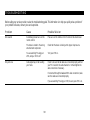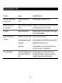
1
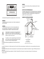
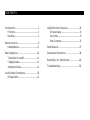
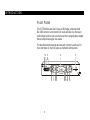
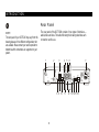
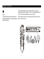
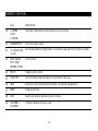
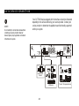
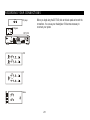
DCT5100
User Guide
CHANNEL
CURSOR
A/B
INFO
MSGS.
A/B
MENU
GUIDE
ON
POWER
USB
VIDEO IN
L AUDIO IN R
SMART CARD
REMOTE
SELECT
REPAIRS
CAUTION
RISK OF ELECTRIC SHOCK
If you find the unit in need of repair, contact your cable system operator for repair or
replacement.
NOTE TO CATV SYSTEM INSTALLER
CAUTION: TO REDUCE THE RISK OF ELECTRIC SHOCK,
DO NOT REMOVE COVER (OR BACK).
NO USER-SERVICEABLE PARTS INSIDE.
REFER SERVICING TO QUALIFIED SERVICE PERSONNEL.
Graphical symbols and supplemental warning marking locations on bottom of terminal.
WARNING
This reminder is provided to call the CATV system installer’s attention to Article 820-40 of
the NEC that provides guidelines for proper grounding and, in particular, specifies that the
cable ground shall be connected to the grounding system of the building, as close as
possible to the point of cable entry as practical.
EXAMPLE OF ANTENNA GROUNDING
Electric service Ground
equipment
clamp
Antenna lead
in wire
TO PREVENT FIRE OR SHOCK HAZARD, DO NOT EXPOSE THIS APPLIANCE TO
RAIN OR MOISTURE.
CAUTION
TO PREVENT ELECTRICAL SHOCK, DO NOT USE THIS (POLARIZED) PLUG
WITH AN EXTENSION CORD, RECEPTACLE, OR OTHER OUTLET UNLESS
THE BLADES CAN BE FULLY INSERTED TO PREVENT BLADE EXPOSURE.
The lightning flash with arrowhead symbol, within an equilateral triangle, is
intended to alert the user to the presence of uninsulated “dangerous
voltage” within the product’s enclosure that may be of sufficient magnitude to
constitute a risk of electric shock to persons.
The exclamation point, within an equilateral triangle, is intended to alert the
user to the presence of important operating and maintenance (servicing)
instructions in the literature accompanying the appliance.
This installation should be made by a qualified service person and should conform to all
local codes.
Antenna
discharge unit
(NEC Section 810-20)
Grounding
clamps
Grounding conductors
(NEC Section 810-21)
Power service grounding
electrode system
(NEC Article 250, Part H)
NEC=NATIONAL ELECTRICAL CODE
Copyright © 2002 by Motorola, Inc. All rights reserved. No part of the contents of this book may be reproduced or transmitted in any form or by any means without written permission
of the publisher.
Dolby Digital is manufactured under license from Dolby Laboratories. “Dolby” and the double-D symbol are trademarks of Dolby Laboratories. Copyright © 2002 Dolby Laboratories. All
rights reserved.
MOTOROLA and the Stylized M Logo are registered in the US Patent & Trademark Office. All other product or service names are the property of their respective owners.
© Motorola, Inc. 2002.
Important Safety Instructions
1
Read instructions
All the safety and operating instructions should
be read before the appliance is operated.
2
Retain instructions
The safety and operating instructions should be
retained for future reference.
3
Heed warnings
All warnings on the appliance and in the
operating instructions should be adhered to.
4
Follow instructions
All operating and use instructions should be
followed.
5
Cleaning
Unplug this product from the wall outlet before
cleaning. Do not use liquid cleaners or aerosol
cleaners. Use a damp cloth for cleaning.
6
Attachments
Do not use attachments not recommended
as they may cause hazard.
7
Water and moisture
Do not use this equipment near water; for
example, near a bath tub, wash bowl, kitchen
sink, or laundry tub, in a wet basement, or near
a swimming pool, and the like.
8
Accessories
Do not place this product on an unstable stand,
cart, tripod, bracket, or table. The product may fall
causing serious injury and damage to the appliance.
Use only with a cart, stand, tripod, bracket, or
table recommended by the manufacturer or sold
with the equipment. Follow the manufacturer’s
instructions when mounting the appliance, and use
a mounting accessory recommended by the
manufacturer.
9
Ventilation
Slots and openings in the cabinet are provided for
ventilation and to ensure reliable operation of the
equipment. The openings should never be blocked
by placing the product on a bed, sofa, rug, or
similar surface. The unit should be positioned with
at least 2 inches of space above and on all sides.
No items should be placed on top of the unit.
Equipment should never be placed near or over a
radiator or heat register, onto heat dissipating
equipment, or in a built-in installation such as a
bookcase unless proper ventilation is provided.
The unit has been designed to operate reliably in a
well-ventilated household environment.
10
Power sources
This product should be operated only from the
power sources indicated on the marking label. If
you are unsure of the type of power supplied to
your home, consult your local power company.
For equipment operating from battery power or
other sources, refer to the operating instructions.
11
Ground or polarization
This equipment may be equipped with a polarized
alternating-current line plug (a plug having one
blade wider than the other). This plug will fit into
the power outlet only one way. This is a safety
feature. If you are unable to insert the plug fully
into the outlet, try reversing the plug. If the plug
should still fail to fit, contact your electrician to
replace your obsolete outlet. Do not defeat the
safety purpose of the polarized plug.
12
Alternate warnings
This equipment may be equipped with a 3-wire
grounding-type plug, a plug having a third
(grounding) pin. This pin will only fit into a
grounding-type power outlet. This is a safety
feature. If you are unable to insert the plug into
the outlet, contact your electrician to replace your
obsolete outlet. Do not defeat the safety purpose
of the grounding-type plug.
13
Power cord protection
Power supply cords should be routed so that they
are not likely to be walked on or pinched by items
placed upon or against them, paying particular
attention to cords at plugs, convenience
receptacles, and the point where they exit from
the appliance.
14
Outdoor Antenna Grounding
If an outside antenna or cable system is connected
to the equipment, be sure the antenna or cable
system is grounded as to provide some protection
against voltage surges and built-up static charges.
15
16
17
18
19
Lightning
For added protection for this equipment during
a lightning storm, or when it is left unattended
and unused for long periods of time, unplug it
from the wall outlet and disconnect the antenna
or cable system. This will prevent damage to
the video product due to lightning and power
line surges.
20
a When the power supply cord or plug is
damaged.
Safety check
Upon completion of any service or repairs to this
video product, ask the service technician to
perform safety checks to determine that the
product is in proper operational condition.
23
Telephone equipment
Observe the following precautions when installing
telephone modem equipment:
or water.
a Never install telephone wiring during a
c If liquid has been spilled, or objects have fallen
lightning storm.
into the equipment.
b Never install telephone jacks in a wet
d If the equipment does not operate normally by
location unless the jack is specifically designed
for wet locations.
following the operating instructions. Adjust
only those controls that are covered by the
operating instructions as an improper
adjustment of other controls may result in
damage and will often require extensive work
by a qualified technician to restore the
equipment to its normal operation.
Overloading
Do not overload wall outlets and extension
cords as this can result in a risk of fire or
electrical shock.
Servicing
Do not attempt to service this equipment
yourself as opening or removing covers may
expose you to dangerous voltage or other
hazards, refer all servicing to qualified
service personnel.
22
b If the equipment has been exposed to rain
Power lines
An outside antenna system should not be
located in the vicinity of overhead power lines
or where it can fall into such power lines or
circuits. When installing an outside antenna
system, extreme care should be taken to keep
from touching such power lines or circuits as
contact with them may be fatal.
Object and liquid entry
Never push objects of any kind into this
equipment through openings as they may touch
dangerous voltage points or short-out parts that
could result in a fire or electrical shock. Never
spill liquid of any kind on the product.
Damage requiring service
Unplug this equipment from the wall outlet and
refer servicing to qualified service personnel under
the following conditions:
e If the equipment has been dropped or cabinet
has been damaged.
f When the equipment exhibits a distinct change
in performance, indicating a need for service.
21
Replacement parts
When replacement parts are required, be sure the
service technician has used replacement parts
specified by the manufacturer or have the same
characteristics as the original part. Unauthorized
substitutions may result in fire, electric shock, or
other hazards.
c Never touch uninsulated telephone wires or
terminals unless the telephone lines have been
disconnected at the network interface.
d Use caution when installing or modifying
telephone lines.
24
Battery usage
Notwithstanding any information provided by
Motorola in this manual regarding the use of
batteries, the end user assumes all responsibility
and liability to use and dispose of batteries in
accordance with all applicable laws, rules and
regulations. Motorola will not be liable to anyone
for the end user's failure to use and/or dispose of
batteries in the proper manner and in accordance
with such laws, rules and regulations, or for any
defect contained in batteries which may cause
injury damage to persons or property.
REGULATORY INFORMATION
Federal Communications Commission Radio and Television Interface Statement for a
Class ‘B’ Device.
This equipment has been tested and found to comply with the limits for a Class B digital
device, pursuant to part 15 of the FCC Rules. These limits are designed to provide
reasonable protection against harmful interference in the residential installation. This
equipment generates, uses and can radiate radio frequency energy and, if not installed and
used in accordance with the instructions, may cause harmful interference to radio
communications. However, there is no guarantee that interference will not occur in a
particular installation.
If the equipment does cause harmful interference to radio or television reception, which can
be determined by turning the equipment off and on, the user is encouraged to try to
correct the interference by one of the following measures:
• Increase the separation between the equipment and the effected receiver
• Connect the equipment on a circuit different from the one the receiver is on
You may find the following booklet, prepared by the Federal Communication Commission,
helpful:
How to Identify and Resolve Radio-TV Interference Problems
Stock No. 004-000-0342-4,
U.S. Government Printing Office
Washington, DC 20402
Changes or modifications not expressly approved by the party responsible for compliance
could void the user’s authority to operate the equipment.
Canadian Compliance
This Class B digital apparatus meets all requirements of the Canadian
Interference-Causing Equipment Regulations. Cet appareil numérique de la classe B
respects toutes les exigences du Règlement sur le matériel brouilleur du Canada.
Declaration of Conformity
According to 47CFR, Parts 2 and 15 for Class B Personal Computers and Peripherals;
and/or CPU Boards and Power Supplies used with Class B Personal Computers, Motorola
BCS, 6450 Sequence Drive, San Diego, CA 92121, 1-800-225-9446, declares under sole
responsibility that the product identifies with 47CFR Part 2 and 15 of the FCC Rules as a
Class B digital device. Each product marketed is identical to the representative unit tested
and founded to be compliant with the standards. Records maintained continue to reflect the
equipment being produced can be expected to be within the variation accepted, due to
quantity production and testing on a statistical basis as required by 47CFR 2.909. Operation
is subject to the following condition: This device must accept any interference received,
including interference that may cause undesired operation. The above named party is
responsible for ensuring that the equipment complies with the standards of 47CFR,
Paragraph 15.101 to 15.109. The Class B digital apparatus meets all requirements of the
Canadian Interface Causing Equipment Regulations.
FCC Part 68 Statement
Industry Canada CS-03 Statement
This equipment complies with part 68 of the FCC rules. On the rear panel of this equipment is a
label that contains, among other information, the FCC registration number and ringer equivalence
number (REN) for the equipment. If requested, this information must be provided to the telephone
company.
The Industry Canada label identifies certified equipment. This certification means that the
equipment meets certain telecommunications network protective, operational and safety
requirements as prescribed in the appropriate Terminal Equipment Technical Requirements
document(s). The department does not guarantee that the equipment will operate to the
user’s satisfaction.
The REN is used to determine the quantity of devices that may be connected to the telephone line.
Excessive RENs on the telephone line may result in the devices not ringing in response to an
incoming call. In most, but not all areas, the sum of the RENs should not exceed five (5.0). To be
certain of the number of devices that may be connected to the line, as determined by the total
RENs, contact the telephone company to determine the maximum REN for the calling area.
This equipment uses the following USOC jack: RJC. An FCC-compliant telephone cord and
modular plug is provided with this equipment. This equipment is designed to be connected to the
telephone network or premises wiring using a compatible modular jack that is Part 68 compliant.
This equipment cannot be used on telephone company-provided coin services. Connection to
Party Line Service is subject to state tariffs.
If this equipment causes harm to the telephone network, the telephone company will notify you in
advance that the temporary discontinuance of services may be required. If advance notice isn’t
practical, the telephone company will notify the customer as soon as possible. Also, you will be
advised of your right to file a complaint with the FCC if you believe it is necessary.
The telephone company may make changes in its facilities, equipment, operations, or procedures
that could affect the operation of the equipment. If this happens, the telephone company will
provide advance notice in order to maintain uninterrupted service.
If the trouble is causing harm to the telephone system, the telephone company may request that
you remove the equipment from the network until the problem is resolved.
Before installing this equipment, users should ensure that it is permissible to be connected
to the facilities of the local telecommunications company. The equipment must also be
installed using an acceptable method of connection. The customer should be aware that
compliance with the above conditions might not prevent degradation of service in some
situations. Only a representative designated by the supplier should coordinate repairs to
certified equipment. Repairs or alterations made by the user to this equipment, or
equipment malfunctions may give the telecommunication company cause to request the
user to disconnect the equipment.
Users should ensure for their own protection that the electrical ground connections of the
power utility, telephone lines and internal metallic water pipe system, if present, are
connected together. This precaution may be particularly important in rural areas. Users
should not attempt to make such connections themselves, but should contact the
appropriate electric inspection authority, or electrician, as appropriate.
The Ringer Equivalence Number (REN) of this device is displayed on the product. The REN
assigned to each terminal device provides an indication of the maximum number of
terminals allowed to be connected to a telephone interface. The termination on an interface
may consist of any combination of devices subject only to the requirement that the sum of
the Ringer Equivalence Numbers of all devices does not exceed 5. The telephone
connection arrangement is a CA11A.
CONTENTS
Introduction ................................................. 2
Front Panel ......................................................................... 3
Rear Panel........................................................................... 6
Remote Control............................................ 9
Installing Batteries...........................................................13
Basic Operation .......................................... 14
Turning Power On and Off..........................................14
Changing Channels.........................................................14
Adjusting the Volume ....................................................14
Audio/Video Connections........................... 15
RF Bypass Switch ............................................................16
High Definition Television ......................... 19
On-Screen Display......................................................... 19
User Options................................................................... 20
Video Connections ........................................................ 26
Data Features ............................................. 27
Data Device Connection ............................. 28
Recording Your Connections ..................... 29
Troubleshooting ......................................... 30
INTRODUCTION
Congratulations on receiving the Motorola DCT5100, the most advanced
interactive digital consumer terminal available today. The powerful
processing capability of the DCT5100 and integrated cable modem bring the
world of high-speed data, internet access, and advanced interactive
applications to your television-viewing environment.
With the appropriate applications and network support, the DCT5100 is
capable of much more than just delivering hundreds of analog and digital
video channels. The DCT5100 can provide exciting services such as
high-definition video, electronic program guides, high-speed data, internet
access, e-mail, Video-On-Demand, video conferencing, IP telephony,
E-Commerce, home banking, and much more. The DCT5100 can interface
to an external data device, such as a PC, using several high-speed
interfaces - Ethernet, USB, or optional IEEE 1394 “Firewire.” These
interfaces enable a PC to share the integrated cable modem resources, as
well as pass data and video to an external device for further processing.
This User Guide introduces you to the basic features of the DCT5100 and
provides several options for integrating it into your current entertainment
system. The advanced features of the DCT5100, such as the cable modem,
are dependent on the applications and network infrastructure supported by
your system. Check with your service provider to determine which features
are being offered in your area. They also provide instructions for the
optional services.
2
INTRODUCTION
Front Panel
The DCT5100 front panel has 12 keys, an LED display, a Universal Serial
Bus (USB) connector, and connectors for audio and video. Use the keys to
perform basic functions such as access the electronic program guide, navigate
menus, and purchase pay-per-view events.
The table following this drawing describes each connection and its use. For
more information on the front panel, see the Remote Control section.
1 2 3
5
4
CURSOR
CHANNEL
A/B
INFO
P
MSGS.
A/B
MENU
GUIDE
ON
POWER
USB
VIDEO IN
6 7 89
3
MUTE
SMART CARD
REMOTE
SELECT
L AUDIO IN R
1011 12 13
INTRODUCTION
Key
Description
1
USB
The Universal Serial Bus (USB) connector is used to support devices such as keyboards, joysticks, scanners,
disk storage, PCs, printers, and digital cameras.
2
VIDEO IN
The VIDEO IN connector accepts a baseband video input from a VCR, camcorder, or other video device.
3
AUDIO IN R
These connectors are used for connecting the set-top between a CD player and a stereo tuner (or other audio
peripheral). Audio from the auxiliary device will pass through the DCT5100 when it is turned off.
AUDIO IN L
4
LED
Displays the channel number or time of day.
There are four indicator lights on the LED screen:
5
SMART
CARD SLOT
CURSOR
6
7
MENU
•
MSGS. — the DCT5100 has received messages for you to read
•
ON — the DCT5100 is powered on
•
A/B — the RF bypass is active
•
REMOTE — the remote control is in use
This interface is intended to support electronic commerce activity utilizing a smart card. Contact your service
provider for availability.
Moves the cursor around the program guide and menu screens.
Displays the main menu.
4
INTRODUCTION
Key
Description
8
POWER
Turns the device on or off.
9
INFO
Displays the current channel and program information (not supported by all applications).
10
A/B
Use to manually enable the RF bypass function. You must have a cable-ready TV for this function to operate.
(Optional.)
11
SELECT
Selects menu options, pay-per-view events or programs from the program guide.
12
GUIDE
Displays the program guide.
13
CHANNEL +
CHANNEL -
Changes the channels by moving up or down.
5
INTRODUCTION
Rear Panel
NOTE
The rear panel of your DCT5100 may vary from this
drawing because of the different configurations that
are available. Please contact your service provider to
determine which connections are supported on your
system.
The rear panel of the DCT5100 consists of two types of interfaces —
audio/video and data. The table following this drawing describes each
connection and its use.
1
3
2
ETHERNET
TO
TV/VCR
5
AUDIO IN
R
L
SPDIF
6
IN
7
VIDEO
OUT
HPNA
IR
CABLE
IN
USB
8 9 10
6
4
L
R
AUDIO
OUT
11
Y
Pb
Pr
TV
Pass Card
IEEE 1394
S-VIDEO
OPTICAL
SPDIF
12 13 14 15 16
SWITCHED
105-125V
60Hz
4A MAX
500W MAX
CONVENIENCE
OUTLET
INTRODUCTION
Key
Description
1
TO TV/VCR
This coaxial output connector is used to connect the DCT5100 to a TV or VCR operating on channel 3 or 4.
2
CABLE IN
The CABLE IN connector receives the incoming signal from your service provider.
3
ETHERNET
The Ethernet port that supports PC networking.
4
AUDIO IN R
These connectors are used for connecting the set-top between a CD player and a stereo tuner (or other audio
peripheral). Audio from the auxiliary device will pass through the DCT5100 when it is turned off.
AUDIO IN L
5
SPDIF
The SPDIF connector is a digital output connection that carries Dolby Digital 5.1 audio or PCM audio.
6
VIDEO IN
The VIDEO IN connector accepts a baseband video input from a VCR, camcorder, or other video device.
VIDEO OUT
The VIDEO OUT connector is used to deliver video to an external device such as a VCR or TV.
7
CONVENIENCE
OUTLET
This AC outlet may be used to connect the power plug from the TV to the DCT5100.
8
IR
This connector enables the DCT5100 to control a VCR while recording a selected program. Not all electronic
program guides support this feature.
9
USB
The Universal Serial Bus (USB) is used to support devices such as keyboards, joysticks, scanners, disk storage,
PCs, printers, and digital cameras.
10
HPNA
This connector enables you to connect your DCT5100 to computers within your home using existing
telephone lines. (Optional.)
7
INTRODUCTION
11
Key
Description
AUDIO OUT R
The RCA phono-type connectors are used to deliver audio to a stereo receiver.
AUDIO OUT L
12
Y – Pb – Pr
These connectors are used to deliver component video.
13
TV PASS CARD
For future use.
14
S-VIDEO
This connector is used to deliver high quality video to external devices that accept S-Video inputs, such as a
high-end VCR or TV.
15
OPTICAL SPDIF
The OPTICAL SPDIF connector is an optical digital output connection that carries Dolby Digital 5.1 audio or PCM
audio.
16
IEEE 1394
This high-speed data interface connector will support PCs, entertainment system devices, data storage, and
future high definition TVs. (Optional.)
8
REMOTE CONTROL
NOTE
The remote control you receive may differ from the
remote control pictured here. Your service provider will
supply user instructions.
The DRC 400 provides basic control of the DCT5100, TV, VCR, and
auxiliary devices such as a second TV or VCR. For programming instructions
refer to the instructions supplied by your service provider.
Notice that many of the keys on the front panel share the same function as
keys on the remote control.
1
VCR
AUX
2
3
4
5
6
7
8
TV
CHANNEL
CURSOR
A/B
P
MSGS.
POWER
PAGE
LOCK
PAGE
EXIT
INFO
14
15
16
A/B
MENU
GUIDE
ON
MUTE
SMART CARD
REMOTE
POWER
USB
VIDEO IN
SELECT
L AUDIO IN R
OK
MENU
VOLUME
9
10
CABLE
INFO
HELP
LAST
CHANNEL
FAVORITE
17
18
CURSOR
CHANNEL
19
THEME
LIST
A
B
C
1
2
3
A/B
INFO
CANCEL
MENU
20
GUIDE
POWER
11
12
4
5
7
8
TV/VCR
6
9
ENTER
0
DAY
STOP
REW
PAUSE
RECORD
13
9
SELECT
DAY
PLAY
F.FWD
21
6
17
3
16 12
7
8
19
REMOTE CONTROL
Use this information with a basic electronic program guide. If your program guide is different, refer to the instructions for your
program guide.
Key
Description
1
AUX, VCR,
CABLE, OR TV
Selects a device to control. The selected mode will remain active until you press another key.
2
HELP
Displays the help screen.
3
POWER
Turns the currently selected device on or off.
4
PAGE
5
EXIT
PAGE
Exits a menu or program guide.
CURSOR
6
Pages through menu screens and the program guide.
Moves the cursor around the program guide and menu screens.
7
OK/SELECT
Selects menu options, pay-per-view events or programs from the program guide.
8
GUIDE
Displays the program guide.
9
VOLUME +
VOLUME -
Increases or decreases the volume of the currently selected device.
10
REMOTE CONTROL
Key
Description
10
A THEME
B LIST
C CANCEL
Functionality is determined from services offered by your service provider.
11
NUMBER KEYS
Use to directly select a channel.
12
TV/VCR BYPASS
or A/B
Use to manually enable the RF bypass function. You must have a cable-ready TV for this function to operate.
13
STOP, PAUSE,
PLAY, REW,
RECORD, F.FWD
Controls the VCR.
14
MUTE
Toggles the sound on and off.
15
LOCK/PPV
Use to limit viewing of selected programs or to view the Pay-Per-View menu.
16
INFO
Displays the current channel and program information (not supported by all applications).
17
MENU
Displays the main menu.
18
LAST
Recalls the last channel or goes back one screen in the menu.
19
CHANNEL +
CHANNEL -
Changes the channels by moving up or down.
11
REMOTE CONTROL
Key
Description
20
FAVORITE
Displays preset favorite cable channels.
21
ENTER/MUSIC
Displays digital music channel menus. On some TV models press to enter channels.
12
REMOTE CONTROL
Installing Batteries
NOTE
Batteries installed incorrectly can cause battery
leakage and corrosion that will damage the remote
control
+
+
Before you can use the remote control, you must install two AA (1.5-volt)
alkaline batteries:
1
Slide open the battery door on the back of the remote control.
2
Insert the batteries in the direction indicated on the inside of the
battery compartment.
3
Slide the battery door closed until it snaps into place.
4
Point the remote control at the DCT5100, press CABLE and then press
POWER. If the DCT5100 does not turn on, check the orientation of the
batteries or replace with new batteries.
Be sure to dispose of batteries in the proper manner and in accordance with the
regulations in your area.
13
BASIC OPERATION
Turning Power On and Off
NOTE
If the TO TV/VCR connector on the DCT5100 is
connected to the coaxial CABLE IN connector on the TV,
you must tune your TV to channel 3 or channel 4.
Occasionally, software updates must be downloaded
from the cable plant to your DCT5100, which may
result in a brief restriction of services.
Press POWER on the front panel, or press CABLE and then press POWER on
the remote control.
Changing Channels
You can change channels in two ways:
•
Press CHANNEL or on the front panel of the DCT5100 or press
CHANNEL + or - on the remote control to step through the channel
selection.
•
Enter the number of the channel you want to tune using the numeric
keys on the remote control.
Adjusting the Volume
Press VOLUME + or – on the remote control to adjust the volume. When
you adjust the volume, the volume scale is displayed on the screen. Press
MUTE on the remote control to turn the sound off and on again.
For best audio quality, use the remote control to set the DCT5100 to
approximately ¾ of maximum volume level and then adjust the audio levels
on the external devices.
14
AUDIO/VIDEO CONNECTI ONS
Before you move or change components on your entertainment system,
review the following:
NOTE
It is important to remember not to place anything on
top of the DCT5100 and to provide for adequate
ventilation to prevent overheating.
•
For basic cable connections, use 75-ohm coaxial cables equipped with
F-type connectors.
•
For audio or video outputs, use cables equipped with RCA-type
connectors.
•
Disconnect power from the DCT5100 before moving it or changing
cable connections.
•
Do not place anything on top of the DCT5100, especially other home
video components.
The DCT5100 requires adequate ventilation and airflow during normal
operation to prevent overheating. The DCT5100 functions reliably in a
normal room-temperature environment. Do not position the DCT5100 in an
enclosed space that would restrict airflow around the unit. Also, do not
position the DCT5100 near any external heat source that could raise the
temperature around the unit.
15
AUDIO/VIDEO CONNECTI ONS
RF Bypass Switch
The DCT5100 may be equipped with the optional RF Bypass switch.
When the optional RF bypass switch is activated, it routes the cable signal
directly to a cable-ready TV, bypassing the DCT5100. This configuration
enables you to view clear analog programming on the direct cable signal
should the DCT5100 be powered off.
AUDIO IN
R
L
ETHERNET
TO
TV/VCR
SPDIF
USB
R
L
AUDIO
OUT
Y
To TV
RF
OUT
CONV
IN
CABLE
IN
From cable outlet
16
VIDEO
OUT
HPNA
IR
CABLE
IN
CONV
OUT
IN
Pb
Pr
TV
Pass Card
IEEE 1394
S-VIDEO
OPTICAL
SPDIF
SWITCHED
105-125V
60Hz
4A MAX
500W MAX
CONVENIENCE
OUTLET
AUDIO/VIDEO CONNECTI ONS
CD player
AUDIO
OUT
R
DCT 5100
Your entertainment system may not support all of these connections.
Audio
loop-thru
AUDIO IN
R
L
ETHERNET
Cable
out
Use these configurations as aides when connecting the DCT5100 into your
home entertainment system.
L
TO
TV/VCR
SPDIF
IN
Y
Pb
VIDEO
OUT
HPNA
IR
CABLE
IN
USB
R
L
AUDIO
OUT
Pr
TV
Pass Card
IEEE 1394
S-VIDEO
OPTICAL
SPDIF
SWITCHED
105-125V
60Hz
4A MAX
500W MAX
From
cable outlet
VCR
Cable
in
Cable
out
R
AUDIO
OUT
This drawing illustrates audio/video connections with a stereo at the end of
the chain. Use this connection to view your TV with sound coming through
your stereo system. An advantage to this connection is that you use one set
of RCA input connectors on your stereo.
It is important to remember:
AUDIO
IN
CABLE IN
CONVENIENCE
OUTLET
L
CABLE OUT
VIDEO IN
S-VIDEO IN
VIDEO OUT
S-VIDEO OUT
•
The channel 3 and 4 coaxial cable connection does not carry stereo
audio for digital channels.
•
The RCA audio connections carry stereo for both analog and digital
channels.
•
The SPDIF connection is capable of passing through Dolby Digital 5.1
audio for those programs offering Dolby Digital content.
TV
AUDIO
IN
Cable
in
R
CABLE IN
AUDIO
OUT
L
VIDEO IN
S-VIDEO IN
VIDEO OUT
Stereo
S
P
E
A
K
E
R
S
AUDIO
IN
R
L
AUDIO
OUT
DIGITAL
IN
17
AUDIO/VIDEO CONNECTI ONS
CD player
AUDIO
OUT
R
DCT 5100
Audio
loop-thru
AUDIO IN
R
L
ETHERNET
Cable
out
This drawing illustrates an audio/video connection with the TV at the end of
the chain. This connection requires two sets of RCA input connectors on
your stereo if you choose to view TV through the stereo system.
L
TO
TV/VCR
SPDIF
IN
Your entertainment system may not support all of these connections.
VIDEO
OUT
HPNA
IR
CABLE
IN
USB
R
L
AUDIO
OUT
Y
Pb
Pr
TV
Pass Card
IEEE 1394
S-VIDEO
OPTICAL
SPDIF
SWITCHED
105-125V
60Hz
4A MAX
500W MAX
From
cable outlet
CONVENIENCE
OUTLET
It is important to remember:
•
The channel 3 and 4 coaxial cable connection does not carry stereo
audio for digital channels.
•
The RCA audio connections carry stereo for both analog and digital
channels.
•
The SPDIF connection is capable of passing through Dolby Digital 5.1
audio for those programs offering Dolby Digital content.
VCR
Cable
in
AUDIO
IN
CABLE IN
Cable
out
R
AUDIO
OUT
L
CABLE OUT
VIDEO IN
S-VIDEO IN
VIDEO OUT
S-VIDEO OUT
Stereo
S
P
E
A
K
E
R
S
AUDIO
IN
R
L
AUDIO
OUT
DIGITAL
IN
TV
AUDIO
IN
Cable
in
R
CABLE IN
AUDIO
OUT
L
VIDEO IN
S-VIDEO IN
VIDEO OUT
18
HIGH DEFINITION TELEVISION
On-Screen Display
The DCT5100 delivers high-quality component video for high definition TVs.
You can use the on-screen display menu to configure your high definition
settings for video display format, closed captioning, and the width-to-height
ratio of your screen.
To access your high definition settings, press the MENU key on the front
panel while the DCT5100 is turned off. If your TV is on, the on-screen
display menu appears listing the settings you can configure. The user settings
will also be displayed on the front panel LED whether your TV is off or on.
However, only the options for Output Type and Closed Caption will be
displayed on the LED.
Use your remote control or the cursor keys on the front panel to navigate
the on-screen display. Press the and keys to highlight the setting you
wish to change. Press the key to select an option for that setting. To exit
the setting and move to another setting, use the and keys.
The high definition settings are described in the table on the following pages.
19
HIGH DEFINITION TELEVISION
User Options
Setting
Option
Description
Output Type
1080I
720P
480P
480I
Selects the video display format. The LED panel will display the output type you have selected.
Defaults to 480I.
When high definition output modes (1080I, 720P, or 480P) are selected, graphic overlays such as electronic
program guides can only be viewed on the component video outputs (Y – PB – PR). The baseband video
output (VIDEO OUT) will continue to transmit baseband video (480I), but without graphic overlays.
Closed Caption
ENABLED
DISABLED
Turns closed captions off or on. The LED panel will display the status of the closed captions.
Defaults to DISABLED.
AUTO
Selects the font size for closed captions. Defaults to AUTO.
Pen Size
STANDARD
LARGE
SMALL
20
HIGH DEFINITION TELEVISION
Setting
Option
Description
Font Style
AUTO
MONO SERIF
PROPORTION
SERIF
MONO NO
SERIF
PROPORTION
NO SERIF
CASUAL
CURSIVE
SMALL
Selects the font style for closed captions. Defaults to AUTO.
21
HIGH DEFINITION TELEVISION
Setting
Option
Description
Foreground
Color
AUTO
WHITE
BLACK
RED
GREEN
BLUE
YELLOW
MAGENTA
CYAN
Selects the foreground color for closed captions. Defaults to AUTO.
Foreground
Opacity
AUTO
TRANSPARENT
TRANSLUCENT
SOLID
FLASHING
Selects the opacity of the closed captions foreground. Defaults to AUTO.
22
HIGH DEFINITION TELEVISION
Setting
Option
Description
Background
Color
AUTO
WHITE
BLACK
RED
GREEN
BLUE
YELLOW
MAGENTA
CYAN
Selects the background color for closed captions. Defaults to AUTO.
23
HIGH DEFINITION TELEVISION
Setting
Option
Description
Background
Opacity
AUTO
TRANSPARENT
TRANSLUCENT
SOLID
FLASHING
Selects the background opacity for closed captions. Defaults to AUTO.
Service Selection
AUTO
PRIMARY
LANGUAGE
SECONDARY
LANGUAGE
3
4
5
6
Selects the service to be used for closed captions. Defaults to AUTO.
24
HIGH DEFINITION TELEVISION
Setting
Option
Description
Settings
AUTO
USER
Selects the default settings for closed captions (AUTO) or the settings you have configured (USER).
Defaults to AUTO.
Aspect Ratio
Mode
LETTERBOX
PAN-SCAN
CROPPED
Selects the width-to-height ratio of your screen. Defaults to LETTERBOX.
Cancel Changes
Exits the High Definition User Settings screen without saving any changes.
Save Changes
Exits the High Definition User Settings screen and saves changes.
You can also press the MENU or POWER key on the DCT5100 to exit and save changes.
25
HIGH DEFINITION TELEVISION
Video Connections
DCT 5100
AUDIO IN
R
L
ETHERNET
TO
TV/VCR
SPDIF
IN
VIDEO
OUT
HPNA
IR
CABLE
IN
R
L
AUDIO
OUT
USB
Y
Pb
Pr
TV
Pass Card
IEEE 1394
S-VIDEO
OPTICAL
SPDIF
SWITCHED
105-125V
60Hz
4A MAX
500W MAX
CONVENIENCE
OUTLET
This drawing illustrates the video connections for your high definition TV.
For information on configuring your HDTV settings, see “High Definition
Settings”.
TV
Component
Video Input
Y
CABLE/
ANTENNA IN
Pb
Pr
26
DATA FEATURES
NOTE
Do not attempt to connect data devices without
contacting your service provider. Advanced data
features require the proper application and network
infrastructure to operate.
The most powerful and exciting features of the DCT5100 involve the data
services supported by this system. The DCT5100 provides high-speed data
services to your TV, such as internet access, IP Telephony, E-Commerce,
and home banking. In addition, the DCT5100 will interface to external data
devices such as those indicated in the section, “Data Device Connection.”
The interfaces illustrated enable a PC to utilize the integrated cable modem,
and accept video/audio data from digital camcorders. The DCT5100 also
supports universal serial bus devices currently available for the PC industry
and high definition television.
Contact your service provider for the available data services.
27
DATA DEVICE CONNECTION
NOTE
Do not attempt to connect data devices without
contacting your service provider. Advanced
features require proper application and network
infrastructure to operate.
Your DCT5100 may be equipped with the interface connections illustrated
depending on the services offered by your service provider. Contact your
service provider to determine the applications and functionality supported
within your system.
AUDIO IN
R
L
ETHERNET
TO
TV/VCR
SPDIF
IN
Y
Pb
VIDEO
OUT
HPNA
IR
CABLE
IN
USB
R
L
AUDIO
OUT
Home Ethernet
Network
TV
Pass Card
IEEE 1394
S-VIDEO
OPTICAL
SPDIF
SWITCHED
105-125V
60Hz
4A MAX
500W MAX
CONVENIENCE
OUTLET
HDTV
USB devices
28
Pr
“Firewire” 1394 equipped devices
RECORDING YOUR CONNECTIONS
AUDIO
OUT
R
CD player
L
RF Bypass
RF
OUT
CONV
OUT
CONV
IN
CABLE
IN
DCT 5100
AUDIO IN
R
L
ETHERNET
TO
TV/VCR
VIDEO
OUT
SPDIF
IN
Y
Pb
HPNA
IR
CABLE
IN
USB
R
L
AUDIO
OUT
Pr
TV
Pass Card
R
AUDIO
OUT
CABLE OUT
OPTICAL
SPDIF
SWITCHED
105-125V
60Hz
4A MAX
500W MAX
CONVENIENCE
OUTLET
VCR
L
VIDEO IN
S-VIDEO IN
L
VIDEO OUT
S-VIDEO OUT
TV
AUDIO
IN
R
IEEE 1394
S-VIDEO
AUDIO
IN
CABLE IN
L
VIDEO IN
S-VIDEO IN
VIDEO OUT
S-VIDEO OUT
AUDIO
OUT
CABLE
IN
S
P
E
A
K
E
R
S
Before you begin using the DCT5100, look at the back panel and record the
connections. You can use your drawing later if it becomes necessary to
reconnect your system.
Stereo
AUDIO
IN
R
L
AUDIO
OUT
DIGITAL
IN
29
TROUBLESHOOTING
Before calling your service provider, review the troubleshooting guide. This information is to help you quickly solve a problem. If
your problem still exists, contact your service provider.
Problem
Cause
Possible Solution
No sound
Accidentally pressed MUTE on the
remote control.
Press MUTE on the remote control to restore the volume level.
The stereo is tuned to the wrong
entertainment component.
Check that the stereo is looking at the proper input source.
You are watching TV using your
VCR, and your VCR is off.
Turn your VCR on.
Cable signal may not be reaching
your home.
Check to be sure that all cables are connected properly and that
your TV is tuned to the cable channel 3 or 4. Hand-tighten the
cable connections if necessary.
No picture
If connected through the baseband RCA video connection, make
sure the cables are connected properly.
If you are watching TV using your VCR, be sure your VCR is on.
30
TROUBLESHOOTING
Problem
Cause
Possible Solution
Picture or sound is noisy
on one channel
Coaxial cable is disconnected
or loose.
Reconnect the cable and hand-tighten if loose.
Sound from only one
stereo speaker
Cable connections are disconnected
or loose.
Hand-tighten or reconnect the cables properly. Ensure that wires
are not frayed and plugs are not bent or broken.
No power
Power cord is disconnected.
Reconnect the power cord. Ensure that the DCT5100 is plugged
into an outlet that is always live.
Remote control does
not work
Remote isn’t set in cable TV mode.
Press CABLE on the remote control.
Obstruction between remote and
cable terminal.
Ensure that nothing is on the DCT5100 or blocking a clear line of
sight between it and the remote control.
Dead batteries.
Change the batteries in your remote control according to the
instructions in the section, “Installing Batteries.”
Audio levels on external devices not
set relative to DCT5100 volume
level.
For best audio quality, use the remote control to set the
DCT5100 to approximately ¾ of maximum volume level and
then adjust the audio levels on the external devices.
Poor audio quality
31
Motorola, Inc.
495012-001
4/02