1
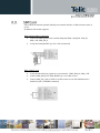
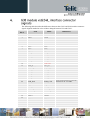
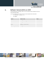
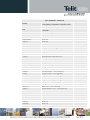
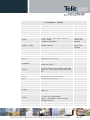
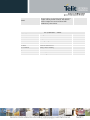
SPECIFICATIONS SUBJECT TO CHANGE WITHOUT NOTICE Notice While reasonable efforts have been made to assure the accuracy of this document, Telit assumes no liability resulting from any inaccuracies or omissions in this document, or from use of the information obtained herein. The information in this document has been carefully checked and is believed to be entirely reliable. However, no responsibility is assumed for inaccuracies or omissions. Telit reserves the right to make changes to any products described herein and reserves the right to revise this document and to make changes from time to time in content hereof with no obligation to notify any person of revisions or changes. Telit does not assume any liability arising out of the application or use of any product, software, or circuit described herein; neither does it convey license under its patent rights or the rights of others. It is possible that this publication may contain references to, or information about Telit products (machines and programs), programming, or services that are not announced in your country. Such references or information must not be construed to mean that Telit intends to announce such Telit products, programming, or services in your country. Copyrights This instruction manual and the Telit products described in this instruction manual may be, include or describe copyrighted Telit material, such as computer programs stored in semiconductor memories or other media. Laws in the Italy and other countries preserve for Telit and its licensors certain exclusive rights for copyrighted material, including the exclusive right to copy, reproduce in any form, distribute and make derivative works of the copyrighted material. Accordingly, any copyrighted material of Telit and its licensors contained herein or in the Telit products described in this instruction manual may not be copied, reproduced, distributed, merged or modified in any manner without the express written permission of Telit. Furthermore, the purchase of Telit products shall not be deemed to grant either directly or by implication, estoppel, or otherwise, any license under the copyrights, patents or patent applications of Telit, as arises by operation of law in the sale of a product. Computer Software Copyrights The Telit and 3rd Party supplied Software (SW) products described in this instruction manual may include copyrighted Telit and other 3rd Party supplied computer programs stored in semiconductor memories or other media. Laws in the Italy and other countries preserve for Telit and other 3rd Party supplied SW certain exclusive rights for copyrighted computer programs, including the exclusive right to copy or reproduce in any form the copyrighted computer program. Accordingly, any copyrighted Telit or other 3rd Party supplied SW computer programs contained in the Telit products described in this instruction manual may not be copied (reverse engineered) or reproduced in any manner without the express written permission of Telit or the 3rd Party SW supplier. Furthermore, the purchase of Telit products shall not be deemed to grant either directly or by implication, estoppel, or otherwise, any license under the copyrights, patents or patent applications of Telit or other 3rd Party supplied SW, except for the normal non-exclusive, royalty free license to use that arises by operation of law in the sale of a product. Usage and Disclosure Restrictions License Agreements The software described in this document is the property of Telit and its licensors. It is furnished by express license agreement only and may be used only in accordance with the terms of such an agreement. Copyrighted Materials Software and documentation are copyrighted materials. Making unauthorized copies is prohibited by law. No part of the software or documentation may be reproduced, transmitted, transcribed, stored in a retrieval system, or translated into any language or computer language, in any form or by any means, without prior written permission of Telit High Risk Materials Components, units, or third-party products used in the product described herein are NOT fault-tolerant and are NOT designed, manufactured, or intended for use as on-line control equipment in the following hazardous environments requiring fail-safe controls: the operation of Nuclear Facilities, Aircraft Navigation or Aircraft Communication Systems, Air Traffic Control, Life Support, or Weapons Systems (High Risk Activities"). Telit and its supplier(s) specifically disclaim any expressed or implied warranty of fitness for such High Risk Activities. Trademarks TELIT and the Stylized T Logo are registered in Trademark Office. All other product or service names are the property of their respective owners. Copyright © Telit Communications S.p.A. 2012. The purpose of this document is to provide G24-L customers with a general overview of the electrical and programming interface differences between G30 and G24-L, and provide a means to integrate the G30 product on a G24-L compatible platform.This document may be used as a reference which outlines the electrical, software and mechanical integration required for transforming a G24-L platform to operate with G30. For further information and detailed specifications please refer to the Developer Manuals of each product. This guide is intended for Telit's G30 customers. For general contact, technical support, to report documentation errors and to order manuals, contact Telit Technical Support Center (TTSC) at: TS-EMEA@telit.com TS-NORTHAMERICA@telit.com TS-LATINAMERICA@telit.com TS-APAC@telit.com Alternatively, use: http://www.telit.com/en/products/technical-support-center/contact.php For detailed information about where you can buy the Telit modules or for recommendations on accessories and components visit: http://www.telit.com To register for product news and announcements or for product questions contact Telit Technical Support Center (TTSC). Our aim is to make this guide as helpful as possible. Keep us informed of your comments and suggestions for improvements. Telit appreciates feedback from the users of our information. Danger – This information MUST be followed or catastrophic equipment failure or bodily injury may occur. Caution or Warning – Alerts the user to important points about integrating the module, if these points are not followed, the module and end user equipment may fail or malfunction. Tip or Information – Provides advice and suggestions that may be useful when integrating the module. All dates are in ISO 8601 format, i.e. YYYY-MM-DD. Revision 0 1 Date 2012-12-20 2013-01-02 Changes First issue Second issue The G30 GSM/GPRS module is available on a LGA 81-pin form factor, and with a 70 pin connector as well, maintaining the same mounting design as the ‘24’ family. This model version is created for customers looking to draw on the G30 feature set, and wish to remain with connectorized solution. The following list of features will be available on G30 modules once migrated from G24-L: AT commands Interface and TCP/IP stacks compatible with the G24 family. Board to Board connector option High compatibility to the “24” family Form Factor and Pin-out. MUX over UART Telit AppZone: embedded application space FOTA Full Duplex Audio Embedded SIM chip technology Telit G30 module was designed with regards to electrical, mechanical and software compatibility to G24-L module. The following is delta within electrical interfaces and features that has to be considered when using G30. Not supported features in G30: EDGE USB ADC3 IGN New supported features in G30: VRTC Esim- Embedded SIM Unit ready indication using reset signal FOTA ATs Appzone application: I2C, SPI Telit G30 current consumption values are different than G24-L. Please refer to the Developer Guide for power consumption values details. Telit G30 supports the following interfaces: UART SPI for logging SIM card I2C (via Appzone SW package) Telit G30 has an internal optional SIM chip and external interface to SIM connector same as G24-L. In addition G30 module supports: When external SIM is connected: Connect all SIM signals to the external SIM pins(VSIM , SIM_RST, SIM_IO, SIM_CLK, SIM_PD_n) Verify that eSIM_RESET (pin 56) is left unconnected When eSIM is used: Verify that the following signals are not connected: VSIM, SIM_IO, SIM_CLK Connect SIM_RST pin to eSIM_RESET pin via O ohm resistor Connect SIM_PD_n pin to GND via O ohm resistor in case the SIM detection is disabled by SW (+MSMPD command) Differences in the audio output and input gain settings between G24-L and G30 may be noticed. Different gain levels for each path need to be set through AT commands, depending on the application. G30 digital audio: PCM bus clock frequency 144 kHz I2S bus CLK - 512 kHz It is important to note that the ON_N signal voltage level is different between the modules. In G24-L the ON_N signal is referenced to logic level. In G30 the PWR_ON, when connecting the power supply for the first time or when reconnects it after a power supply loss, G30 will power-on. The G30 is turned-on automatically when external power is applied above the minimum operating level. This difference may affect customers using this signal if their design does not follow the recommendation in the Developer Manuals: "The PWR_ON input signal is set high by an internal pull-up resistor whenever a power supply is applied to the module. Therefore, it is recommended to operate this signal by using an open collector/drain circuit connection." Turning ON Using ON_N: G24-L: Asserting the ON_N signal low for a minimum of 500 milliseconds and a maximum of 1.5 seconds will cause the G24-L to turn-on. G30: Asserting the ON_N signal low for a minimum of 600 milliseconds will cause the G30 to turn-on. Turning OFF Using ON_N: G24-L: Asserting the ON_N signal low for a minimum of 2 seconds. G30: Asserting the ON_N signal low for a minimum of 3 seconds. Telit G30 can support current of up to 30mA, when in G24-L the current is 150mA. In G30 input is from module In G24-L output is from module The following table describes the differences between the G24-L and G30 interface connector signals. Signals marked in color red have changed between G30 and G24-L. Connector G30 G24-L Differences Pin # 1 GND GND 2 3 4 5 6 7 8 9 10 11 12 13 14 15 16 17 18 19 20 21 GND GND GND VCC VCC VCC VCC RTS_N CTS_N WKUPI_N DCD_N RXD_DAI DTR_N TXD_DAI TXD_N GND GND GND VCC VCC VCC VCC RTS_N USB_VBUS RXD_N USB_DP DSR_N USB_DN CTS_N WKUPI_N DCD_N PCM_DIN DTR_N PCM_DOUT TXD_N 22 CLK_DAI PCM_CLK 23 24 25 26 27 28 29 30 31 32 33 RI_N WA0_DAI RESET_N WKUPO_N VREF GPIO1 RI_N PCM_FS RESET_N WKUPO_N VREF GPIO1 GPIO2 GPIO2 GPIO3/SDA GPIO3 RXD_N DSR_N G30 clock operates at 144 kHz I2S bus CLK - 512 kHz Connector Pin # 34 35 36 37 38 39 40 41 42 43 44 45 46 47 G30 G24-L GPIO4/SCL GPIO4 GPIO5 ADC1 GPIO6 GPIO5 ADC1 GPIO6 GPIO7 ANT_DET GPIO8 ADC2 SIM_RST_N GPIO7 ANT_DET GPIO8 ADC2 SIM_RST_N UID SIM_CLK ADC3 SIM_CLK 48 VSIM SIM_VCC 49 50 51 52 53 54 55 56 57 58 59 60 61 62 63 64 65 66 67 68 69 70 GPRS SIM_PD_N GPRS SIMPD_N IGN SIM_DIO ON_N LCD_CS HDST_INT_N LCD_SD HDST_MIC LCD_CLK AGND LCD_RS MIC SPI_IRQ_N ALRT_N SPI_DIN ALRT_P SPI_CLK SPKR_N SPI_DOUT SPKR_P SPI_CS SIM_DIO PWR_ON _N HDST_SPK HDST_INT_N eSIM_RESET HDST_MIC AGND1 VRTC MIC SPI_IRQ SPKR_N SPI_MISO SPKR_P SPI_CLK SPKR_N SPI_MOSI SPKR_P SPI_CS Differences G30 supports also 1.8V SIM cards The mechanical design is similar between G24-L and G30. The differences in the modules are in connectors and height, as described below. G24-L uses MMCX, while G30 uses U.FL connector for the radio RF interface. The application interface connector is a single 70-pin, 0.5mm pitch, 2 rows, board-to-board interconnect type. G24-L Dimensions (70 Pin connector) Physical: 24.4x45.2x.6.5mm Weight <9g G30 Dimensions (70 Pin connector) Physical: 24.4x40x.3.5mm Weight <6g The following table is providing a full overview on software features differences between G24-L and G30 modules. To use commands that are equal to G24 Lite send command to the G30 module: • AT+MSELINT = 1(default is “0”) • AT+MRST Feature Status in G30 USB UART2 E-mail SSL FOTA Date Book ME memory (SMS, PB) Not supported UART2 is Not supported Not supported supported – future release supported – future release Not supported Not supported Values AT Commands – Removed EGPRS +MEGA STK +MFIC +CTFR1 +MNTFY +MCHARGE +MEGA +MDMIC +CVIB +MPDPM +TCLCC +MKPD +TSMSRET +TWUS +TWUR +TASW +TADIAG +MVREF +MNTFY +MPSU +CKPD +CKEV +CDEV +MUPB +CSNS +MDSI +MCSN +MCSAT +MEDT +MEMISP +MEMAS +MEMGS +MEMDE +MEMSE +MEML +MEMR +MEMD EGPRS commands removed (CGEQREQ,CGEQMIN,CGEQNEG,CEG) Email Gateway Address Removed Motorola commands replaced by IFX commands. Filter Incoming Calls, Removed Reject incoming call, Removed Removed Removed Removed Removed Vibrator alert, Removed PB dynamic Percentage Mem. Removed List of current call Removed Keypad control Removed SMS Sending Retry Removed Wakeup Reason Set Removed Wakeup Reason Request Removed Antenna Switch Removed Query antenna ADC value Removed Motorola Voltage Reference Removed Notify Indication Removed Second UART Removed Keypad Control – Not supported Keypress Echo – Not supported Display Indication – Not supported Phone Book Event – Not supported Single Numbering – Not supported Deactivate SIM – Not supported Change Subscriber Number- Not supported SMS Alert – Not supported Enable/Disable Tone – Not supported Removed Removed Removed Removed Removed Removed Removed Removed +MEMW +MFS +MTDTR +MTCTS +MMAR +EMPC +MIPCSC,MIPSSL +MIPCFF +EPIN +MGEER +MHDPB +MIAU Ignore commands FTS, FRH, FRM, FRS, FTH, FTM, FPR Phone Book Feature Fax Feature AT$ Removed Frequency of Search – Not supported DTR line – Not supported CTS line – Not supported Removed Subsidy Lock – Not supported SSL - Not supported Removed Removed GPRS Error – Not supported Headset dual position – Not supported Removed Backward compatibility, Removed Class 1 commands, Removed Removed Removed List of all available commands, Removed AT Commands – Updated +MMICG ATI[n] +CRTT Character Set Baud rate FAX +CPBS Range supported is 0-15 Updated 16 Ring Tones instead of 41 Replace ASCII with IRA. UTF8 Removed Value 13 (460800), Removed Class 2 1) AD, DC, EN, MC and RC – Removed 2) LD – Added 3) Replace SD with SN +CPBS / +CPMS ME/MT removed +CSMS +CIND/+CIEV +CCWA GPIOs S94, S96 FTP Value 128, removed. Different indications Indication will appear only once. Update to 9 GPIO pins Supported range, enlarged Use different sockets that the 4 for MIPOPEN In case of result 0 (operation failed) the FTP connection is close 1) Range updated. 2) <rst>=0-<fun> value won’t be saved in the flex/<rst>=1-<fun> value will be saved in the flex Cell ID, LAC, Removed Will support subsidy lock feature Advance mode, Removed At commands per channel, Removed Range updated Support up to 2 strings Read Mode, removed Registers: 14,21,22,31,36,39,40 and 41 – Removed Set and Read Mode, removed Speeds 14(14400 bps (V.34), 68 – 2400 bps (V.110 or X.31 flag stuffing) and 75 – 14400 bps (V.110 or X.31 flag stuffing), removed Value 1 from parameter <name> removed Read Mode, added +FTPRETR +CFUN +MCI +CLCK MUX MUX +CNMI +CNUM Q, E, X S register +CEER +CBST +CBST +GCAP Currently PB feature is not supported Currently PB feature is not supported S register +MAPATH/ +MAVOL S6, S8 and S18, assed The parameters: <keep_alive_timeout>, <keepalive_interval>, <keepalive_probes>, removed 1) Only 2 converters 2) Average not supported Alert speaker, removed Dial from PB Only full equally string can be dial +MIPCONF +MMAD +MIPSEND Audio +CLVL / +MAVOL +CCWA +CGPRS D, Dial +ICF +CSMS +CNMA+CNMI +CSCA +IPR +CGCLASS +CSCS +CSCS +MIPSEND +CFUN +CFUN S94 +CPWD S24 +CGDCONT +MCELL +CMER +CRSL when reached the watermark an unsolicited report of +MIPPUSH will be display While in advance mode, all basic commands are not block and will not return error. Only MAPATH will invoke advance mode. The level value is added to the value was set in the other command and does not replace this value When no <class>, the default is 1 Value 2(EDGE), removed Limit of 54 digits Values: 4,5,6,8 removed Parameter <service> updated Commands updated Command updated Values 300,600 removed Values CC and CG added CS 8859-1 removed HEX character set is treated as GSM Max size to send 504 bytes Remove second parameter <rst> from Set Mode When disable phone transmit & receive RF the module perform power down 0 = Disable sidetone All barring services use the same password The G30 will wake up from sleep mode and timer will reset only in case the DTE wakes up the module. In case of a report to the terminal the G30 continue to sleep Parameter <cid> range is (1-2) Screens updated Command parameters updated 0 = lowest volume Currently PB feature is not supported SMS +CBAND +CTZU, +CTZR +MTSM +MADCM +CCID +CSIM +CGCMOD \Q +MATONE +MMICV When reading an incoming SM, the message header will be passed as usual. The DATA will be output in as received from NW without any conversions AT Commands – Added Change radio band NITZ commands Temperature sensor measurement Analog to digital measurement Card ID Generic SIM Access PDP Context Modify Set Flow Control Tone Play Mic voltage value