1
lVLYI:AG
Series
Nine
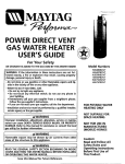
ELECTRIC
WATE R HEATER
USER'S GUIDE
Model
Numbers
HE2930T
HE3930T
HE2940L
HE3940 L
HE2940S
HE3940S
HE2940T
HE3940T
HE2950S
HE3950S
HE2950T
HE3950T
HE2966T
HE3966T
_
FOR POTABLE WATER
HEATING ONLY
LISTED
GAMA certification applies to all residential
electricwater heaterswith capacitiesof 20 to
120 Gallons, Input rating of 12 Kw or lessat a
voltage
no greater
NOT SUITABLE FOR
SPACE HEATING
than 250 V.
AWARNING
I
COVER AND THEN THIS ENTIRE MANUAL BEFORE INSTALLING OR
READ THE GENERAL
SAFETY
SECTION BEGINNING ON INSIDE
OPERATING
THIS WATER
HEATER.
r
Save this Manual
for Future
Reference.
Caution:
Read and Follow
Operating
All
Instructions
safety
andof
Before Rules
First Use
This Product.
Safety Instructions
_WARNING
AWARNING
Improper installation, adjustment, alteration, service
or maintenance can cause DEATH, SERIOUS BODILY
INJURY, OR PROPERTY DAMAGE. Refer to this manual for assistance consult your local utility or call
Maytag Customer Service at 1-800-788-8899 for an
authorized servicer for further information,
At the time of manufacture this water heater was provided with a combination temperature-pressures relief
valve certified by a nationally recognized testing laboratory that maintains periodic inspection of production
of listed equipment or materials, as meeting the
requirements for Relief Valves and Automatic Gas
IShutoff Devices for Hot Water Supply Systems, and
the latest edition of ANSI Z21.22 and the code requirements of ASME. If replaced, the valve must meet the
requirements of local codes, but not lessthan a combination temperature and pressure relief valve certified
as meeting the requirements for Relief Valves and
Automatic Gas Shutoff Devices for Hot Water Supply
Systems, ANSI Z21.22 by a nationally recognized testing laboratory that maintains periodic inspection of
production of listed equipment or materials.
The valve must be marked with a maximum set pressure not to exceed the marked hydrostatic working
pressure of the water heater (150 Ibs./sq. in.) and a
discharge capacity not less than the water heater
AWARNING
HAZARD OF ELECTRICAL SHOCK! Before removing
any access panels or servicing the water heater,
make sure the electrical supply to the water heater
is turned "OFF". Failure to do this could result in
DEATH, SERIOUS BODILY INJURY, OR PROPERTY
DAMAGE.
_WARNING
HOTTER WATER CAN SCALD: Water heaters are
intended to produce hot water. Water heated to a
temperature
which will satisfy clothes washing,
d sh washing, and other sanitizing needs can scald
and permanently injure you upon contact. Some
people are more likely to be permanently injured by
hot water than others. These include the elderly,
children, the infirm, or physically/mentally
handi-,
capped. If anyone using hot water in your home fits
into one of these groups or if there is a local code or
state law requiring a certain temperature water at
the hot water tap, then you must take special precautions. In addition to using the lowest possible
temperature settingthat
sattsfies your hot water
needs, a means such as a mixing valve, should be
used at the hot water taps used by these people or
at the water heater. Mixing valves are available at
plumbing supply or hardware stores. Follow manutacturers instructions for installation of the valves,
Before changing the factory setting on the thermostat, read the "Temperature Regulation" section in
this manual,
(Electric heaters - watts divided by 1000 x 3415 equal
BTU/Hr. rate.)
input
ratejurisdictional
as shown authority,
on the model
rating plate.
Your local
while mandating
the
use of a temperature-pressure relief valve complying
with ANSi Z21.22 and ASME, may require a valve model
different from the one furnished with the water heater.
Compliance with such local requirements must be satisfied by the installer or end user of the water heater
with a locally prescribed temperature-pressure relief
valve installed in the designated opening in the water
heater in place of the factory furnished valve.
For safe operation of the water heater, the relief valve
must not be removed from it's designated opening or
plugged.
The temperature-pressure
relief valve must be
installed directly into the fitting of the water heater
designated for the relief valve. Position the valve
downward and provide tubing so that any discharge
will exit only within 6 inches above, or at any distance
below the structural floor. Be certain that no contact is
made with any live electrical part. The discharge opening must not be blocked or reduced in size under any
circumstances. Excessivelength, over 30 feet, or use of
more than four elbows can cause restriction and
reduce the discharge capacity of the valve.
No valve or other obstruction is to be placed between
the relief valve and the tank. Do not connect tubing
directly to discharge drain unless a 6 air gap is provided. To prevent bodily injury, hazard to life, or property
damage, the relief valve must be allowed to discharge
water in quantities should circumstances demand. If
the discharge pipe is not connected to a drain or other
suitable means, the water flow may cause property
damage.
The Discharge Pipe:
• Must notbe smaller in size than the outlet pipe size I
of the valve, or have any reducing couplings or I
other restrictions.
I
I
I
I
AWARNING
INSULATING JACKETS: When installing an external
water heater insulation jacket on an electric water
heater:
• DO NOT cover the temperature-pressure relief valve,
• DO NOT put insulation over the access covers or
any access areas,
• DO NOT cover or remove operating instructions,
and safety related warning labels and materials
affixed to the water heater,
: Must
notofbematerial
pluggedlisted
or blocked.
Must be
for hot water distribution.
AWARNING
I
| Do not use this ap_part
of it has been /
/ under water. An electrical short or malfunction could |
[occur. The water heater should be replaced.
]
2
of both
temperature-pressure
relief valve,
and
• Must
be the
installed
so as to allow complete
drainage
the discharge pipe.
• Must terminate at an adequate drain.
• and
Musttank.
not have any valve between the relief valve
Safety Instructions (cont'd)
AWARNING
WATER HEATERS EQUIPPED FOR ONE VOLTAGE
ONLY: This water heater is equipped for one type
voltage only. Check the rating plate near the bottom access panel for the correct voltage. DO NOT
use this water heater with any voltage other than
the one shown on the model rating plate. Failure to
use the correct voltage can cause problems which
can result in DEATH, SERIOUS BODILY INJURY, OR
PROPERTY DAMAGE. If you have any questions or
doubts consult your electric company.
A,CAUTION
WATER HEATERS EVENTUALLY LEAK: Installation of
the water heater must be accomplished in such a
manner that if the tank or any connections should
leak, the flow of water will not cause damage to the
structure. For this reason, it is not advisable to install
the water heater in an attic or upper floor. When
such locations cannot be avoided, a suitable drain
pan should be installed under the water heater.
Drain pans are available at your local hardware
store. Such a drain pan must have a minimum diameter of at least 1% inches greater than the water
heater diameter and must be piped to an adequate
drain. Under no circumstances Is the manufacturer or
Maytag to be held liable for any water damage in
connection with this water heater.
l
Table of Contents
Safety Instructions ..............................................................................................
2-3
Table of Contents ...............................................................................................
4
Customer Information .......................................................................................
s
Product Specifications .......................................................................................
6
Accessories and Tools Needed .........................................................................
7
Accessories ............................................................................................................................................................................
Tools .....................................................................................................................................................................................
7
7
Instructions for Installation ..............................................................................
s-17
Removing the Old Water Heater ..........................................................................................................................................
Locating the New Water Heater ..........................................................................................................................................
Typical Installation ................................................................................................................................................................
The Convertible Lower Element ........................................................................................................................................
8
9
9
10
Water Piping .......................................................................................................................................................................
Temperature-Pressure Relief Valve .....................................................................................................................................
Filling the Water Heater .....................................................................................................................................................
11
12
13
Converting the Lower Element .....................................................................................................................................
Wiring Diagrams ................................................................................................................................................................
Wiring ................................................................................................................................................................................
Installation Checklist ..........................................................................................................................................................
13-1.5
16
17
18
Service and Maintenance ..................................................................................
19-24
Temperature Regulation ......................................................................................................................................................
Thermostats ........................................................................................................................................................................
Thermostat Settings ............................................................................................................................................................
Thermostat Adjustment ......................................................................................................................................................
Temperature-Pressure Relief Valve Operation ....................................................................................................................
Draining ..............................................................................................................................................................................
Element Cleaning and Replacement .............................................................................................................................
Drain Valve Washer Replacement ......................................................................................................................................
Service .................................................................................................................................................................................
Troubleshooting
19
19
19
20
20
21
21-24
24
24
.................................................................................................
2s-27
Start Up Conditions ............................................................................................................................................................
Thermal Expansion ........................................................................................................................................................
Strange Sounds ...............................................................................................................................................................
Operational Conditions ................................................................................................................................................
Smelly Water ..................................................................................................................................................................
Air in Hot Water Faucets ...............................................................................................................................................
25
25
25
25, 26
25
25
Rumbling Noise .............................................................................................................................................................
High Temperature Shut Off System ........................................................................................................................
Not Enough Hot Water .................................................................................................................................................
Water is Too Hot ...........................................................................................................................................................
25
25, 26
26
26
Leakage Checkpoints .....................................................................................................................................................
27
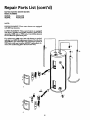
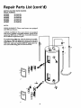
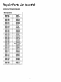
Repair Parts List .................................................................................................
28-34
Warranty ..............................................................................................................
36
Customer Information
ThankYou
for purchasing a Maytag water heater.
• The installation must conform with the instructions in this
manual; electric company rules; and Local Codes, or in the
absence of Local Codes, with the latest edition of the
Properly installed and maintained, it should give you years of
trouble free service. It is strongly suggested that this new
water heater be professionally installed, call Maytag Customer
Service at 1-800-788-8899 for recommended installers,
Abbreviations
Found
In This
Instruction
National Electrical Code. This publication is available from
your local government or public library or electric company
or by writing Underwriters Laboratories Inc., 333 Pfingsten
Manual
Road, Northbrook, IL 60062.
U.L.- Underwriters Laboratories, 333 Pfingsten Rd.,
Northbrook, IL 60062
National Electrical Code-This
• If after reading this manual you have any questions or do
not understand any portion of the instructions, call Maytag
Customer Service at 1-800-788-8899 for an authorized
servicer.
publication is available from
your local government or public library or electric company or
by writing to U.L. above.
ANSI-American National Standards Institute
• Carefially plan the place where you are going to put the
• Read the "Safety Instructions" section, pages 2 and 3 of this
water heater. Correct electrical wiring and connections are
very important in preventing death from possible electrical
shock and fires.
manual first and then the entire manual carefully. If you
don't follow the safety rules, the water heater will not operate properly. It could cause DEATH, SERIOUS BODILY
INJURY AND/OR PROPERTY DAMAGE.
Examine the location to ensure the water heater complies
with the "Locating the New Water Heater" section.
This manual contains instructions for the installation, operation, and maintenance of this electric water heater. It also
contains warnings throughout the manual that you must
read and be aware of. All warnings and all instructions are
• For California installation this water heater must be braced,
anchored, or strapped to avoid falling or moving during an
earthquake. See instructions for correct installation procedures. Instructions may be obtained from the California
office of the State Architect, 400 P Street, Sacramento, CA
95814.
essential to the proper operation of the water heater and
your safety. Since we cannot put everything on the first few
pages, READ THIS ENTIRE MANUAL BEFORE
ATTEMPTING
TO INSTALL OR OPERATE THE
WATER HEATER.
• Massachusetts Code requires this water heater to be
installed in accordance with Massachusetts 248-CMR 2.00:
State Plumbing Code and 248-CMR 5.00.
5
Product Specifications
Model
HE2930T
HE3930T
Tank Capacity
In Gallons
Element
Wattage
Upper
Recovery Rate
In Gals Per Hr.
Upper
HE2940L
HE3940L
HE2940S
HE3940S
HE2940T
HE3940T
30
40
40
40
3800
3800
3800
3800
et_ovok_wer3800
I _5003800
1_5003800
I 55®3800
I _500
17.3
17.3
17.3
17.3
_90"F_se
_wer173I 25 173I 25 173I 2_ 173I 25
Diameter
18"
24"
20"
18"
Height
Ma_dmum Fuse or
Circuit Breaker Size
46"
31.5"
47"
59.5"
20
30
20
30
20
30
20
30
12
10
12
10
12
10
12
10
Minimum
Wire Size (Gauge)
Model
HE2950S
HE3950S
HE2950T
HE3950T
50
50
66
3800
3800
3800
Tank Capacity
In Gallons
Element
Wattage
at240Volt
Upper
Lower
Recovery Rate
In Gals Per Hr.
Upper
--
@90*PRise
Diameter
Lower
3800
[
5500
3800
17.3
17.3
[
23"
[
5500
HE2966T
HE3966T
3800
17.3
25
17.3
46.25"
[
5500
17.3
[
25
20"
17.3
58"
[
22"
25
Height
Maximum Fuse or
Circuit Breaker Size
60.25"
20
30
20
30
20
30
*Minimum
Wire Size (Gauge)
12
I0
12
10
12
I0
*Wiring size based on standard 60"C copper wire. If distance from fuse box to water heater is more than 90 feet, refer to your local
electrical code.
Accessories and Tools Needed
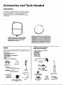
Accessories
To simplify the installation Maytag has available the installation parts shown below. You may or may not need all of these
accessories depending on your type of irtstaUation. Call
Maytag Customer Service at 1-800-788-8899
for an authorized installer.
•
r,
EXPANSIONTANKSFORTHERMAL EXPANSION
CONDITIONSAVAILABLEIN 2 GALLON(PART
NUMBER66001013) AND SGALLON(PART
NUMBER66001014) CAPACITY
DRAINPANSAVAILABLEIN 22" DIAMETER(PART
NUMBER66001011) FORWATERHEATERSHAVING
A DIAMETER20" OR LESS,24" DIAMETER(PART
NUMBER66001105) FORWATERHEATERSHAVING
A DIAMETER22u OR LESSAND AVAILABLEIN 28"
DIAMETERIPARTNUMBER 66001012) FORWATER
HEATERSHAVING A DIAMETER26.25" OR LESS
TOOLS
ADDITIONAL
TOOLS NEEDED
WHEN SWEAT SOLDERING
You may or may not need all of these tools, depending on your
type of installation.
These tools can be purchased at your local
lVlaytag store.
•
•
•
•
•
Pipe Wrenches (2) 14"
Screwdriver
6 Foot Tape of Folding
Garden Hose
Drill
• Pipe
*
*
•
•
*
*
Rule
dope or Teflon Tape
Tubing Cutters or Hacksaw
Propane Torch
Soft Solder
Solder Flux
Emery Cloth
Wire Brushes
_1
"
6 FOOTTAPE
GARDENHOSE
3/4_ WIRE BRUSH
SLOT-HEADSCREWDRIVER
_
PIPE
WRENCH
112" WIRE BRUSH
ROLLOF LEADFREE
PIPEDOPE
(SQUEEZE
PHILLIPS
TUBE) SCREWDRIVER
_
'
_
ROLLOF TEFLONTAPE
(Useonly on water connections)
_ _ SOLDER
SOFT
ROLLOF EMERY
CLOTH
DRILL
7
_
SOLDERFLUX
PROPANETORCH
TUBINGcUTrER
Instructions for Installation
Removing the Old Water Heater
QTurn
"OFF" electrical supply to the water heater.
('_
copper
a. If you have
piping to the water heater, the two
copper water pipes can be cut with a hacksaw approxi-
too short. Additional cuts can be made later if necessary. Disconnect
mately
four inchestheaway
temperature-pressure
from where they relief
connect
valve
to
drain fine. When the water heater is drained, disconnect the hose from the drain valve. Close the drain
valve. The water heater is now completely disconnectthe water heater. This will avoid cutting off the pipes
ed and ready to be removed.
watertheaterat
the water shutoff valve
QTUrnorwa ermeter."OFF"
the water supply to the
I_Q
a
to
water
Attach
hose
the
heater drain
valve and put the other end in a floor
_[_--
heater drain valve. Open a nearby hot
drain faucet
or outdoors.
Open
thepressure
water
water
which will
relieve
in the water heater and speed draining,
'[1
Ob.
If you have galvanized pipe to the water
with a pipe wrench at the union in each
heater,Also
loosen
the twothegalvanized
pipes
line,
disconnect
piping remaining to the water heater. These pieces
should be saved since they may be needed
l_]
Disconnect
the temperature-pressure
relief valve discharge pipe. When the
water heater is drained, disconnect the
hose from the drain valve. Close the drain
valve. The water heater is now completely
The water &WARNING
passing out of the drain
valve may be extremely
hot. To
avoid being scalded, make sure all
connections are tight and that the
water flow is directed away from
any person.
Q
I _
"
disconnected and ready to be removed.
Check again to make sure the electrical supply is turned
"OFF" to the water heater. Then disconnect the electrical supply connection
from the water heater junction
bOX.
Mineral buildup or sediment
may have accumulated I
ACAUTION
in the old water heater. This causes the water[
mtlI
-_lb
_
heater to be much heavier than normal and this
residue, if spilled out, could cause staining.
8
Instructions for Installation (cont'd)
Locating The New Water
Heater
ACAUTION
WATER HEATERSEVENTUALLYLEAK: Installation of the
water heater must be accomplished in such a manner
that if the tank or any connections should leak, the flow
of water will not cause damage to the structure. Forthis
reason, it is not advisable to install the water heater in
You should carefully choose an indoor location for the new
water heater, because the placement is a very important consideration for the safety of the occupants in the building and
an attic or upper floor. When such locations cannot be
avoided, a suitable drain pan should be installed under
the water heater. Drainpans are available at your local
hardware store. Such a drain pan must have a minimum
diameter of at least 1¾ inches greater than the water
heater diameter and must be piped to an adequate
drain. Under no circumstances is the manufacturer or
for the most economical use of the appliance. This water
heater is not intended for outdoor installation,
Whether replacing an old water heater or putting the water
Maytag
to bethis
held
liable
for any water damage in connection with
water
heater.
heater in a new location, the following critical points must be
observed.
1. The location selected should be indoors as close to and as
il CAUTION
]1
INSTALLATION IN RESIDENTIAL GARAGES: The water I
centralized with the water piping system as possible. This
heatermustbe locatedand/or protectedso it isnotl
subject to physical damage by a moving vehicle.
water heater, as well as all water heaters, will eventually
leak. Do not install without adequate drainage provisions
J
where water flow will cause damage.
2. The location selection must provide adequate clearances for
servicing and proper operation of the water heater.
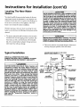
Typical Installation
VACUUM.EQO,RED
SOME
CODES
(REFER
TO LOCALCODES)
CONSULT THE LOCAL UTILITY COMPANY TO EXAMINE INSTALLATION FOR PROPRIETY AND SAFETY.
* &WARNING
f
"oO;LW
I
HOTTER WATER CAN SCALD: Water heaters are
intended to produce hot water. Water heated to a I
CHECK ALL CONNECTIONS FOR LEAKS..
temperature
which will satisfy clothes washing,
SHUTOFF
VALVE
CO,
DW,T R,NLE
ELBOW
UNIO
_
N__
°t
_,
and permanently
dish
washing, and injure
other sanitizing
you upon needs
contact.
can Some
scald I T_REDL__
_
OUTLET*MIXINGVALVE
people are more likely to be permanently injured by
hot water than others. These include the elderly,
/
/
children, the infirm, or physically/mentally
handicapped. If anyone using hot water in your home fits
ELECTRICAL
JUNCTION
BOX
into one of these groups or if there is a local code or
state law requiring a certain temperature water at
the hot water tap, then you must take special precautions. In addition to using the lowest possible
temperature settingthat
satisfies your hot water
needs, a means such as a mixing valve, should be
used at the hot water taps used by these people or
at the water heater. Mixing valves are available at
plumbing supply or hardware stores. Follow manu-
3/4,,THREADED
_'3_NTH_oRS
D
"e_TEMPERATURE"
PRESSURE
RELIEF
VALVE
--DISCHARGE
PIPE
(Do not cap
or plug)
tacturers
instructions
for installation
of the
the thermovalves.
Before changing
the factory
setting on
stat, read the "Temperature Regulation" section in
/
this manual.
_'-{-6" AIRGAP
_ro
9
DRAINVALVE
SUITABLE
DRAIN
Instructions for Installation (cont'd)
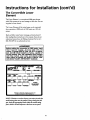
The Convertible
Element
Lower
The Upper Element, is a conventional 3800 watt element
which only operates at its rated wattage on 240 volts. (See rating plate on water heater).
The Lower Element of the water heater can be converted
from operation at 3800 watts to 5500 watts on a 240 volt
system.
Read and follow water heater warnings and instructions.If
after reading these instructions in this manual, if you do not
understand any portion, call Maytag Customer Service at 1800-788-8899 for an authorized servicer.
&WARNING
Before making the conversion to 5500 watts, check
the (1) power supply...must
be 240 volts, (2)
wiring...10 gauge AWG @ Type TW, 60°C or equivalent, and (3) Circuit breakers or fusing...capable of
30 amp loading. Also, the installation must conform
with this manual, local codes and electric utility
rules. Failure to comply can result in DEATH, SERIOUS BOD LY NJURY, OR PROPERTY DAMAGE.
I' TT- I-
NOTE:
Whether
it-i
or not the element conversion is made the
model rating plate must be marked. Using a hard point ink
pen, check the appropriate block within the model rating
plate, which is located adjacent to the lower access panel.
10
Instructions for Installation
(cont'd)
Water Piping
AWARNING
[
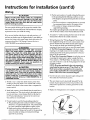
2. Look at the top cover of the water heater. The cold water
I
HoI"rER WATER CAN SCALD: Water heaters are
intended to produce hot water. Water heated to a
I temperature
which will satisfy clothes washing, I
dish washing, and other sanitizing needs can scald
md permanently injure .you upon contact. Some
)eople are more likely to be permanently injured by
inlet is marked cold. Connect the cold water pipe to the
cold water inlet of the water heater.
NOTE:Your water heater is super insulated to minimize
heat loss from the tank. Further reduction in heat loss can
lot water than others. These include the elderly,
children, the infirm, or physically/mentally handicapped. If anyone using hot water in your home fits
into one of these groups or if there is a local code or
state law requiring a certain temperature water at,
the hot water tap, then you must take special pre-
be accomplished by insulating the hot water lines from the
water heater.
SHUT-OFF
cautions. In addition
to using
the your
lowesthotpossible
I
temperature
setting
water]
needs, a means
such that
as a satisfies
mixing valve,
should
be
HOTOUTLET
.HOUSE TO
at the water heater. Mixing valves are available at
plumbing supply or hardware stores. Follow manuBefore changing the factory setting on the thermostat, read the "Temperature Regulation" section in
th s manua.
facturers instructions for installation of the valves.
Ifa water heater is installed in a closed water supply system; such
as one having a hack-flow preventer, check valve, water meter
VALVE_
_
SWEATCOUPLING
SWEATCOUPLING
3/4" THREADED
-- _
THREADED
T
NIPPLE
_
with a check valve, etc. in the cold water supply; means shall be
provided to control thermal expansion. Contact the local utility
or caI1Maytag Customer Service at 1-800-788-8899 for an
authorized servicer on how to control this situation.
,_,_
_=_
iv
--
3/4"
THREADED
THREADED
NIPPLETO
o
_
_
U
/
_/
(._
3q
TEMPERATUREPRESSURE
RELIEF
VALVE
DISCHARGE
PIPE
(Do not capor plug)
NOTE: To protect against untimely corrosion of hot and
cold water fittings, it is strongly recommended that di-electric unions or couplings be installed on this water heater
when connected to copper pipe.
NOTE: The secondary anode rod/hot outlet nipple and the
cold inlet nipple are packaged separately with the water
_
[[
heater. The above parts must be installed in the appropriate
--_
HOT and COLD water connection locations.
,,.
The illustration shows the attachment of the water piping to
the water heater. The water heater is equipped with 3/4inch
water connections.
NOTE: If using copper tubing, solder tubing
before attaching the adaptor to the cold water
tion. Do not solder the cold water supply line
cold water inlet. It will harm the dip tube and
tank.
COLDINLET
WATERLINE
_"
(_/
_6"
AIRGAP
FLOORDRAIN
to an adapter
inlet connecdirectly to the
damage the
1. Look at the top cover of the water heater. The water outlet
is marked hot. Connect the hot water pipe to the hot water
outlet of the water heater.
11
Instructions for Installation (cont'd)
Temperature-Pressure
Relief Valve
•,WARNING
At the time of manufacture this water heater was provided with a combination temperature-pressuresrelief valve
certified by a nationally recognizedtesting laboratory that
maintains periodic inspection of production of listed
equipment or materials, as meeting the requirements for
Relief Valves and Automatic Gas Shutoff Devices for Hot
Water Supply Systems, and the latest edition of ANSI
Z21.22 and the code requirements of ASME. If replaced,
the valve must meet the requirements of local codes, but
not less than a combination temperature and pressure
relief valve certified as meeting the requirements for
Relief Valves and Automatic Gas Shutoff Devices for Hot
Water Supply Systems,ANSI Z21.22 by a nationally recognized testing laboratory that maintains periodic inspection
of productionof listed equipment or materials.
The valve must be marked with a maximum set pressure
not to exceed the marked hydrostaticworking pressureof
the water heater (150 Ibs./sq. in.) and a discharge capacity
not lessthan the water heater input rate as shown on the
model rating plate. (Electric heaters - watts divided by
1000 x 3415 equal BTU/Hr.rate.)
Your local jur|sdictional authority, while mandating the
use of a temperature-pressurerelief valve complying with
ANSI Z21,22 and ASME, may require a valve model different from the one furnished with the water heater.
Compliance with such localrequirements must be satisfied
by the installer or end user of the water heater with a
Iocallyprescribed temperature-pressure relief valve
installed
in the
designated opening in the water heater in
place of the
factoryfurnishedvalve.
_,WARNING
The temperature-p_lve
must be manually operated at least once a year. Caution should be
taken to ensure that (1) no one is in front of or
around the outlet of the temperature-pressure relief
valve discharge line, and (2) the water manually discharged will not cause any bodily injury or property
damage because the water may be extremely hot.
If after manually operating the valve, it fails to completely reset and continues to release water, immediately close the cold water inlet to the water heater,
follow the draining instructions, and replace the
temperature-pressure relief valve with a new one.
HOT
_
_
I
I
I
I
OLD
[_
,___'_
. r,_
CONDUIT/
(_
_
PRESSURE
RELIEF
VALVE
_L
III
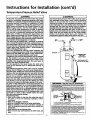
For safe operation of the water heater, the relief valve
must not be removed from it's designated opening or
plugged.
The temperature-pressure relief valve must be installed
directly into the fitting of the water heater designated for
I the relief valve. Positionthe valve downward and provide
tubing so that any dischargewill exit only within 6 inches
above, or at any distance below the structural floor. Be
certain that no contact is made with any live electrical
part. The discharqe opening must not be blocked or
reduced in size und'erany circumstances.Excessivelength,
over 30 feet, or use of more than four elbows can cause
restrictionand reducethe dischargecapacity of the valve.
No valve or other obstructionis to be placed between the
relief valve and the tank. Do not connecttubing directly to
dischargedrain unlessa 6" air gap is provided. To prevent
bodily injury, hazard to life, or property damage, the relief
valve must be allowed to discharge water in quantities
should circumstances demand. If the dischargepipe is not
connected to a drain or other suitable means, the water
flow may cause property damage.
DISCHARGE
PIPE
_TEMPERATURE"
_ (Do not capor plug)
r.-.--t_=
IRGAP
V4ARNING
"RELIEF VALVE OPENING"
_==_=d_V_,_A_O_=G.S_H=W_S_S_,_,k_'I__'*=_=_
__0_*_ _._onTe,_=u.
Re_V_N=_._
*_
,_o_,
_¢_A,_fQE.
Your _:alc°°ejul_de_Jo_
i_ledty, whilemandal_gfile useof a Temperaturs_essareRsl_efWivecomping
_hANBZ21_2andASME.ma_qureavalvem0eqldhf_'e_tl_nthe0ne/
c_=_,_=_,_,_,,_,_,_
a locallypre_
Temperature-Pressure
ReliefValve installedin 1hedesign_teqopeningin the water
_"_
TANK ;1' /_,h !:
JACKET
TANK
F._ G
/-
.
BRASS
COUPLING
VALVE PROBE
MUST EXTEND
• Must not be smaller in size than the outlet pipe size of
the valve, or have any reducing couplings or other
restrictions.
INTO TANK
TEMPERATUREPRESSURE
=
_RA_B
Must
not
be plugged or blocked.
• Must be of material listedfor hot water distribution.
• Must be installed so as to allow complete drainage of
both the temperature-pressurerelief valve, and the discharge pipe.
• Must terminate at an adequate drain,
• Must not have any valve between the relief valve and
•
RELIEF VALVE
S_
• _f a short shank (/e=,,sthan 2"1 temperature-pressurerelief vaJveis to be instalisd
I_eshown),
anipple
and
coupling
must
beused
• Ifalongshank(2'orfo_jer)istobeins_llbe,
do_tusetbenipp_eandcoupling.
"ln_l
Temper_re-Pressureprotec_eequipment
by k_*a]codes,butnotle=
I_ s combination Temperature-Pressure
ReliefValve ced_faid req0ired
as meetingthe
requirementsfor ReliefValves
and
Autome_c
Gas
Shutofl.Devces
for
Bet-Water
Bu Systems,
ANS
Z21,22
by
ana_Jonaby
recogNzeq
test_g is_oratpffthat men_m _I_
inseq_onP_p_
offinal equipmentor marian, Thevafw
_beo.nt_,_o_deq*_,,_,_o_,_,_=_s_g,=_o_ly*_al_h.
shove,
0ratan_distancebdowthealmcturalfloor,
andcar_0tcontactanyliveked/icdparL"
Forsais
opera,on0f thewaterheater,the RdiefValvernustnotbe
removed0rplu
tank.
See manual heading- "Temperature*Pressure
ReliefValve' for inst_llationPe_l_d_int_arce of Relief
Valve+ddsd_agepipeandothersafet_precau_ons
12
Instructions for Installation (cont'd)
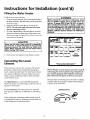
Filling the Water Heater
A WARNING
To fill the water heater with water:
1. Close the water heater drain valve by turning the handle to
the right (clockwise). The drain valve is on the lower front
of the water heater,
Before making
the conversion
to 5500 watts, check
be 240 volts, (2)
wiring...10 gauge AWG @ Type TW, 60°C or equiva-
2. Open the cold water supply valve to the water heater,
NOTE: The cold water supply valve must be left open
whenthewaterheaterisinuse,
lent,
andloading.
(3) Circuit
breakers
or fusing...capable
of
30 amp
Also,
the installation
must conform with this Manual, local codes and electric utility rules. FAILURE TO COMPLY CAN RESULT IN
DEATH, SERIOUS BODILY INJURY OR PROPERTY
DAMAGE.
the (1) power supply...must
3. To insure complete filling of the tank, allow air to exit by
opening the nearest hot water faucet. Allow water to run
until a constant flow is obtained. This will let air out of the
water heater and the piping.
•
ELECTRICWATER HEATER
Never use this water
heater unless it is completely
&CAUTION
m
I"--_'_--
full of water.
heating
element,
To prevent
the tank
damage
must tobethe
filled
tank with
and
IF_v_r"
,_
water. Water must flow from the hot water faucet
before turning "ON" power.
I
u_m
Bzo •
"i
_
_
_=
u__,_l_._
m,_,_,_
_
I
]
I
I
I
._w_Em
_
*Arm _c_* _._,,_''*__
_
WAXll41JM
I
lpa50, I
m
WAR_NQ
4. Check all r_ewwater piping for leal_s. Repair as needed.
WATT8
WaY'Ill
Convertingthe Lower
Element
W,_TrS
IFCOttl_ml_
_ _61rRucTIO_
eo_t_o,
is.Tramark
of
Maytag
Cor
pcatJon
and
is used under License to State Indus_ies, Inc
These instructions only cover the conversion of the convertible element, read this entire manual before attempting to
install or operate the water heater. The water heater is factory
set to operate at 3800 watts. The lower element can be converted to operate at 5500 watts. Refer to "The Convertible
Lower Element" section.
NOTE: Whether or not the element conversion is made the
model rating plate must be marked. Using a hard point ink
pen, cheek the appropriate block within the model rating
plate, which is located adjacent to the lower access panel.
Necessary element conversion parts are located in a small bag
The Upper Element is a conventional 3800 watt element
which only operates at its rated wattage on 240 volts. (See rating plate on water heater).
contained within the large plastic manual envelope attached
to the side of the water heater.
CONVERSION
PARTS
The Lower Element of the water heater can be converted
from operation at 3800 watts to 5500 w_tts on a 240 volt sys-
If after reading these instructions and this manual, if you do
not understand any portion, call Maytag Customer Service at
m
1-800-788-8899
BUSSBAR
for an authorized servicer.
13
Instructions
Converting
(cont'd)
for Installation
(cont'd)
the Lower Element
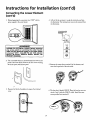
1. Before beginning the conversion turn "OFF" electric
power supply to the water heater,
4. Lift out the tab as shown to uncfip the terminal cover from
the thermostat. The terminal cover can now be removed from
the thermostat.
L;ft out tab to uncllp
terminal cover from
thermostat,
_WARNING
HAZARD OF ELECTRICAL SHOCK! Before removing
any access panels or servicing the water heater,
make sure the electrical supply to the water heater
is turned MOFF". FAILURE TO DO THIS COULD
RESULT IN DEATH, SERIOUS BODILY INJURY, OR
PROPERTY DAMAGE.
2. The convertible element is located behind the lower access
panel of the water heater. Remove the two screws securing
the access panel, and remove panel.
5. Remove the screws from terminal 2 of the element, and
move the looped end of the wire aside.
d
3. Remove the block of insulation to expose the terminal
cover.
6. The buss bar is labeled 5500 W. Place the buss bar over terminals 2 and 3 with the 5500 W visible. Install the extra
screw provided into terminal 3.
14
Instructions for Installation (cont'd)
Converting
(cont'd)
the Lower Element
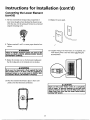
7. The wire removed from terminal 2 has a looped end. It
must remain looped and now be placed (as shown) on top
of the buss bar, over the opening of terminal 2, and secured
11. Replace the accesspanel.
using the remaining screw.
8. Tighten terminals 2 and 3 to ensure proper electrical con-
d
nectlo_.
A WARNING
Failure to tighten terminal screws can cause a fire I
which can result in DEATH,SERIOUSBODILYINJURY,
OR PROPERTYDAMAGE.
12. Complete wiring to the water heater, or if completed, turn
"ON" electric power to the water heater after fallingthe
tank with water.
9. Replace the terminal coveron the thermostat making sure
that the lockingtabs on the terminal coverare in place.
&WARNING
I
Make sure the thermostat is flush against the tank, I
the terminal cover is in place, and the insulation is I
replaced. Failure to do so can result in DEATH,SERIOUS BOD LY NJURY,OR PROPERTYDAMAGE.
%
10. Place the insulation block back in place so that it completely coversthe thermostat and element.
&,CAUTION
Never use this water heater unless it is completely I
full of water. To prevent damage to the tank and I
heating element, the tank must be filled with water. I
turning
"ON"flow
power,
Water must
from the hot water faucet before
15
Instructions for Installation (cont'd)
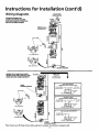
Wiring Diagrams
ToELE R,C
POWERSUPPLY
STANDARD
WIRING
2 WIRE LEAD
WATERFOR
HEATERS
NON-SIMULTANEOUS OPERATION
240 VOLT DOUBLE ELEMENT
BLACK [
, ,_,
D
UPPERE.C.O.&
r"
/
THERMOSTAT
L
h
I
_
S BAR_
ELEMENT
f%
UPPER
FOR 5500WAITS
FOR 3800 wATrs
WIRING FOR 3 WIRE LEAD WATER
HEATERSNON-SIMULTANEOUS OPERATION 240 VOLT DOUBLE ELEMENT
YELLOW
LOWER
HEATINGELEMENT
THREE
TYPES
OF FIELD
CONNECTIONS
--
YOU
MAY
HAVE
1.
TIME CLOCK
OPERATES BOTTOM
UPPER
HEATING
ELEMENT
/
TO
ELECTRIC
SWITCH
ELEMENT
,
ONLY
_
TO TIME
ju
POWER
,BUSSBAR_
_
SUPPLY
I_1 L2
YELLO
OPERATES
_
BOTTOM
ELEMENT
L1 L2-'P
3.
FOR TWO
TO ELECTRIC
POWER SUPPLY
"OFF PEAK
METER
CK
NCTION
BOX
WIRE
LI
YELLO ]_BkA
Use only the 2 terminals
16
CONNECTION
I
L2
LOWER
HEATINGELEMENT
may have 4 terminals.
ONLY
TO
L2E
YELLO I_1_,
Limit switches
SWITCH
_OFFPEAK"METER
2.
FOR SSO0 WATTS
*Note: Some Lower Hi-Temp
N
CLOCK
CK
TO ELECTRIC
_
POWER SUPPLY
L1
_
L2 L2
on left.
CK
tNCTIONBox
Instructions for Installation (cont'd)
Wiring
A CAUTION
C. Flexible metal conduit or 3 metallic tubing shall be permit-
Never use this water heater unless it is completely
full of water. To prevent damage to the tank and
heating element, the tank must be filled with
water. Water must flow from the hot water faucet
before turning on power,
ted for grounding ifaU the following conditions aremet:
1. The length in anyground return path doesnot exceed
6 feet.
2. The circuit conductorscontained therein areprotected
by overcurrent devices rated at 20 amperes or less.
3. The conduit or tubing is terminated in fittings
approved for grounding.
For complete grounding details and all allowable exceptions,
refer to the latest edition of the National Electrical Code.
You must provide all wiring of the proper size outside of the
water heater. You must obey local codes and electric company
requirements when you install this wiring,
If you are not familiar with electric codes and practices, or if
you have any doubt, even the slightest doubt, in your ability to
condust opening has been made m the water
4. A standard ' /2.....
heater junction box for the conduit connection.
connect the wiring to this water heater, obtain the service era
competent electrician. Call Maytag Customer Service at
1-800-788-8899 for an authorized servicer,
5. Wiring Diagrams (See "Wiring Diagrams" Section) have
been supplied showing the two most common types of connections between the water heater and the power supply.
You can easily see which type connection you have by
A WARNING
removing the junction box cover on top of the water heater.
A. Two Wire Connection Diagrams: is the most common
requiring you to simply connect red to red, black to black,
and the ground wire to the green ground screw in the junetion box of the water beater.
B. Three Wire Connection Diagram: is usedwhen you are
connecting the water heater to power a supply that has a
WATER HEATERS EQUIPPED FOR ONE VOLTAGE
ONLY: This water heater is equipped for one type
voltage only. Check the rating plate near the buttom access panel for the correct voltage. DO NOT
use this water heater with any voltage other than
the one shown on the model rating plate. Failure to
use the correct voltage can cause problems which
can result in DEATH, SERIOUS BODILY INJURY, OR
PROPERTY DAMAGE. If you have any questions or
doubts consult your electric company,
"Time Clock" or "Off Peak" Meter. To make these connections refer to block 1 or 2 in this wiring diagram for the type
of system you have.
NOTE: If you have purchased a three wire connection
water heater but you are not on a"Time Clock" or"Off
A CAUTION
If wiring from you r fuse box or circuit breaker box
was aluminum for your old water heater, replace it
with copper wire. If you wish to reuse the existing
aluminum wire, have the connection at the water
Peak" meter and have a standard two wire connection
power supply, simply follow the connection diagram in
block 3 of the Three Wire Connection Diagram.
heater made by a competent
electrician.
Call
Maytacj
Customer
Service
at
1-800-788-8899
for
an
authorized servicer,
6. Use wire nuts and connect the power supply wiring to the
wires inside the water heater's junction.
7. The water heater must be electrically "grounded" by the
installer. A green ground screw has been provided on the
water heater's junction box. Connect ground wire to this
1. Provide a way to easily shut off the electric power when
working on the water heater. This could be with a circuit
breaker or fuse block in the entrance box or a separate disconnect switch,
location.
8. Replace the wiring junction cover using the screw provided.
2. Instal1 and connect a circuit directly from the main fuse or
circuit breaker box. This circuit must be the right size and
have its own fuse or circuit breaker. Refer to the chart in
the "Product Specifications" section for the correct size
wire and fuse or circuit breaker.
CO
3. If metal conduit is used for the grounding conductor:
A. The grounding electrode conductor shall be of copper,
aluminum, or copperclad aluminum. The material shall
B. Rigid metal conduit, intermediate metal conduit, or
electrical metallic tubing may be used for the grounding
means if conduit or tubing is terminated in fittings
be of one continuous length without a splice or joint.
approved for grounding.
17
___
(._
Instructions for Installation (cont'd)
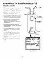
Installation
1. Whether
Checklist
COLD
HOT
or not the element conversion is made, the model
rating plate must be marked. Using a hard point ink pen,
check the appropriate block within the model rating plate,
which is located adjacent to the lower access panel.
2. Is the fuse or circuit breaker size correct as shown in the
chart in the "Product Specifications" section?
CONDUIT
3. Axe the wires from the circuit breaker or fuse service to the
water heater's junction box on the correct wire size (gauge) as
.TEMPERATUREPRESSURE
_
4. Is the new temperature-pressure relief valve properly
shown in the chart in the "Product Specifications" section?
installed, and piped to an adequate drain? See
"Temperature-Pressure Relief Valve" in the "Instructions
RELIEF
VALVE
_
(Do not capor
plug)
for ]nstailation" section,
5. Is the water heater completely filled with water? See
"Filling the Water Heater" instructions in the "Instructions
for Installation sectton.
6. Will a water leak damage anything? See "Locating the
New Water Heater in the Instructions for Installation
section.
6"AIRGAP
7. Axe the cold and hot water lines connected to the water
heater correctly? See "Water Piping" instructions in the
"Instructions for Installation" section.
FLOORDRAIN
8. Is there adequate clearance for maintenance around the
water heater?
9. Do you need to call your eiectric company to checkyour
wiring?
_
m
,
_
_
ttL _.
WATm
_,¢. GI_y
F mlT_imago_1
N_mwt
IIEE_
_
W_NO
® Mayteg is a Tradernarkof May_,g Corporationand
is u_d ¢mdorL_enso to St_W Ind_st_ee,I_
MODEL RATING PLATE
18
p.g.i,
Service and Maintenance
Temperature Regulation
_WARNING
HOTTER WATER CAN SCALD: Water heaters are
intended to produce hot water. Water heated to a
temperature
which will satisfy clothes washing,
dish washing, and other sanitizing needs can scald
and permanently injure you upon contact. Some
people are more likely to be permanently injured by
hot water than others. These include the elderly,
children, the infirm, or physically/mentally
handicapped. If anyone using hot water in your home fits
into one of these groups or if there is a local code or
state law requiring a certain temperature water at
the hot water tap, then you must take special precautions. In addition to using the lowest possible
temperature setting that satisfies your hot water
needs, a means such as a mixing valve, should be
used at the hot water taps used by these people or
at the water heater. Mixing valves are available at
plumbing supply or hardware stores. Follow manutacturers instructions for installation of the valves.
Before changing the factory setting on the thermostat, read the "Temperature Regulation" section in
this manual.
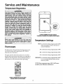
LOWER THERMOSTAT ADJUSTABLE
THROUGH OPENING IN LOWER ACCESS PANEL
AWARNING
Never allow small children to use a hot water tap,
or to draw their own bath water. Never leave a
child or handicapped person unattended in a bath-I
tub or shower.
J
T^
_.,=mvero=ure
.
HOT-Is
Thermostats
c .+--
a thermostat setting of approximately 120°F,
which will supply hot water at the most economicaltemperatures.
The thermostats of this water heater have been factory set at
their lowest position which approximates 120°F (Hot) to
reduce the risk of scald injury.
A-Is a thermostat setting of approximately 130°F.
The upper and lower thermostat is factory set at its lowest
position which approximates 1200F (Hot) and is adjustable if
C-Is a thermostat setting of approximately 1500F.
B-Is a thermostat setting of approximately 140°F.
a different water temperature is desired. Read all warnings in
this manual and on the water heater before proceeding.
VERY HOT-Is
a thermostat setting of approximately 160°F.
It is recommended that the dial be set lower
whenever possible.
NOTE: Water temperature range of 120"-140°F recommended by most dishwasher manufacturers.
UPPER THERMOSTAT ADJUSTABLE
BEHIND UPPER ACCESS PANEL
19
Service and Maintenance
Thermostat Adjustments
(cont'd)
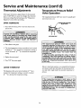
Temperature-Pressure
Valve Operation
If the upper thermostat is adjusted above the factory preset
point of 120°F (Hot), it cannot be set higher than the lower
thermostat setting. Read all warnings in the "Temperature
Regulation" section before proceeding.
The temperature-pressure
ated at least once a year.
UPPER THERMOSTAT
relief valve must be manually oper-
/
/
1. Turn "off" the electtic power to the water heater at the
junction box.
Relief
_31_
TEMPERATURE-PRESSURE
RELIEF
VALVE
__
AWARNING
HAZARD OF ELECTRICAL SHOCK! Before removing
any access panels or servicing the water heater,
make sure the electrical supply to the water heater
is turned "OFF". Failure to do this could result in
DEATH, SERIOUS BODILY INJURY, OR PROPERTY
DISCHARGE
PIPE
_,WARNING
DAMAGE.
The temperature-pressure
relief valve must be
manually operatedat
least once a year. Caution
should be taken to ensure that (1) no one is in front
of or around the outlet of the temperature-pressure relief valve discharge line, and (2) the water
manually discharged will not cause any property
damage
or bodily injury. The water
may be
extremely hot.
If after manually operating the valve, it fails to
completely reset and continues to release water,
immediately close the cold water inlet to the water
heater, follow the draining
instructions,
and
rep ace the temperature-pressure
re ief valve witf
a new one.
2. Take offthe access panel,
3. The slotted adjustment (using a screwdriver) can be turned
clockwise (t'-_
to increase the temperature setting or
counterclockwise
setting,
(¢"-_
to decrease the temperature
4. Replace the accesspanel,
5. Turn "ON" the power supply,
LOWER
Failure to install and maintain a new properly listed temperature-pressure relief valve will release the manufacturer from
THERMOSTAT
The adjustment dial can be turned clockwise (_--'_) to
increase the temperature setting or counter clockwise
(_-'_)
to decrease the temperature setting.
any claim which might result from excessive temperature or
pressure.
_WARNING
If the temperature-pressure
relief valve on the
appliance weeps or discharges periodically, this
may be due to thermal expans on. Your water
I heater may have a check valve installed in the
water line or a water meter with a check valve. Call
Maytag Customer Service at 1-800-788-8899 for an
authorized servicer. Do not plug the temperaturepressure relief valve.
2O
Service and Maintenance (cont'd)
Draining
Element
Cleaning/
I_ ._1
acement
nep,
The water heater should be drained if being shut down during
freezing temperatures. Also periodic draining and cleaning of
sediment from the tank may be necessary,
NOTE: These instructions are written for element cleaning
and element replacement for the lower element. If it is necessary to clean or replace the upper element, then repeat
these instructions.
1. Before beginning turn "OFF" the electric power supply to
the water heater.
To remove the element from your tank in order to clean or
lk WARNING
replace it:
HAZARD OF ELECTRICAL SHOCK! Before removing
any access panels or servicing
the water heater,
make sure the electrical supply to the water heater
is turned "OFF". Failure to do this could result in
1. Before beginning turn "OFF" the electric power supply to
the water heater.
DEATH, SERIOUS BODILY INJURY, OR PROPERTY
2. CLOSE the cold water inlet valve to the water heater.
3. OPEN a nearby hot water faucet and leave open to aUow
for draining.
DAMAGE.
4. Connect a hose to the drain valve and terminate to an adequate drain or outdoors.
_.
AWARNING
5. OPEN the water heater drain valve to allow for tank
HAZARD OF ELECTRICAL SHOCK! Before removing
any access panels or servicing the water heater,
make sure the electrical supply to the water heater
is turned "OFF". Failure to do this could result in
DEATH, SERIOUS BODILY INJURY, OR PROPERTY
DAMAGE.
draining,
NOTE: If the water heater is going to be shut down and
drained for an extended period, the drain valve should be
left open with hose connected allowing water to termihate to an adequate drain.
2. Turn off the water supply to the water heater at the water
shutoffvalve or water meter.
6. Close the drain valve,
7. Follow "Filling the Water Heater" instructions in the
"Instructions for Installation" section.
,,,_----_-_
8. Turn "ON" power to the water heater.
A, CAUTION
Never use this water heater unless it is completely
full water. To prevent damage to the tank and heating element, the tank must be filled with water.
Water must flow from the hot water faucet before
turning "ON" power.
21
_
Service and Maintenance (cont'd)
3. Attach a hose to the water heater drain valve and put the
other end in a floor drain or outdoors. Open the water
heater drain valve. Open a nearby hot water faucet which
will relieve pressure in the water heater and speed draining.
AWARNING
6.
Lift out the tab as shown to unclip the terminal cover from
the thermostat. The terminal cover can now be removed
from the thermostat.
7.
Disconnect the two wires on the element and unscrew the
old element from the tank.
I
The water passing out of the drain valve may be
extremely hot. To avoid beingscalded, make sure all [
connections are tight and that the water flow is
directed away from any person.
4. RemoVeremove
panel.the
two screws securing the access panel, and
_.
4
J
_
a..dj
A_'X_
_
sediment from or around the element opening and inside
.Z
_
1
the tank.
_
8.
Clean the _area around the element opening. Remove any
_'
5. Remove the block of insulation to expose the terminal
9,
If you are cleaning the element you have removed, do so
by scraping or soaking in vinegar or a de-liming solution,
covcr.
Replacement elements must (1) be the same voltage and (2) no greater wattage than listed on the
mode rating p ate AWARNING
aft xed to the water heater.
22
I
Service and Maintenance (cont'd)
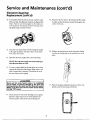
Element Cleaning/
Replacement (cont'd)
10. A new gasket should be used in all cases to prevent a pos-
15. Reconnect the two wires to the element and then check
slble water leak. (See Element Gasket in the Repair Parts
Chart). Place the new element gasket on the thread side
of the cleaned or new element and screw into tank, secur-
to make sure the thermostat remains firmly against the
surface of the tank.
ing tightly using an element wrench.
11. Close the water heater drain valve by turning the handle
to the right (clockwise). The drain valve is on the lower
front of the water heater,
16. Replace the terminal cover on the thermostat making
sure that the locking tabs on the terminal cover are in
place.
12. Open the cold water supply valve to the water heater.
NOTE: The cold water supply valve must be left open
when the water heater is in use.
13. To insure complete falling of the tank, allow air to exit by
opening the nearest hot water faucet. Allow water to run
until a constant flow is obtained. This will let air out of
the water heater and the piping.
A CAUTION
Never use this water heater unless it is completely
full of water. To prevent damage to the tank and
heatingmust
element,
be filledfaucet
with before
water,
Water
flow the
fromtank
the must
hot water
17. Place the insulation block back in place so that it completely covers the thermostat and element.
turning nON" power.
14. Check element for water leaks. If leakage occurs, tighten
element or repeat steps 2 and 3, remove element and
reposition gasket. Then repeat steps 10 through 14.
23
Service and Maintenance (cont'd)
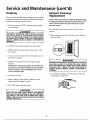
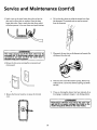
Drain Valve Washer
Replacement
18. Replace access panel.
NOTE: For replacement, use a 17/_"x lye" x 1/s"thick washer
available at your nearest hardware store. For ordering a
19. Turn "ON" electric power to water heater,
replacement washer, refer to the "Repair Parts" section.
1. Before beginning turn "OFF" the electrical power supply
to the water heater.
&WARNING
HAZARD OF ELECTRICAL SHOCK! Before removing
any access panels or servicing the water heater,
make sure the electrical supply to the water heater
is turned UOFFR. Failure to do this could result in
DEATH, SERIOUS BODILY INJURY, OR PROPERTY
DAMAGE.
2. Follow "Draining" instructions in the "Service and
Maintenance" section.
3. Turning counter clockwise, remove the hex cap below the
screw handle.
4. Remove the washer and put the new one in place.
5. Screw the handle and cap assembly back into the drain
valve and retighten using a wrench. DO NOT OVER
TIGHTEN.
6. Follow "Filling the Water Heater" instructions in the
"Instructions for Installation" section.
7. Check for leaks.
8. Turn "ON" electric power to the water heater.
_'_ HANDLEAND
•
_ CAPASSEMBLY
' 'WAS.ER
Service
Before calling for repair service, read the "Start Up
Conditions" and "Operational Conditions" found in the
"Troubleshooting" section of this manual.
If a condition persists or you are uncertain about the operation of the water heater, let a qualified person check it out.
Call Maytag Customer Service at 1-g00-788-8899.
24
Troubleshooting
Start Up Conditions
THERMAL
EXPANSION
Smelly water may be eliminated or reduced in some water heater
models by replacing the anode(s) with one of less active material,
and then chlorinating the water heater tank and all hot water
fines. Call Maytag Customer Service at 1-800-788-8899 for an
authorized servicerfor further information concerning an Anode
Replacement Kit #66001068 and this Chlorination Treatment.
Water supply systems may, because of such events as high line
pressure, frequent cut-offs, the effects of water hammer
among others, have installed devices such as pressure reducing
valves, check valves, back flow preventers, etc...to control
these types of problems. When these devices are not equipped
with an internal by-pass, and no other measures are taken, the
devices cause the water system to be closed. As water is heated, it expands (thermal expansion) and closed systems do not
allow for the expansion of heated water,
If the smelly water persists after the anode replacement and chlorination treatment, we can only suggest that continuous chlorination and filtering conditioning equipment be considered to eliminate the water problem.
The water within the water heater tank expands as it is heated
and increases the pressure of the water system. If the relieving
point of the water heater's temperature-pressure reliefvalve is
Do not remove the anode leaving the tank unprotected. By
doing so, all warranty on the water heater tank is voided.
reached, the valve will relieve the excess pressure. The temperature-pressure relief valve is not intended for the constant
"AIR"
IN HOT
WATER
FAUCETS
_,WARNING
relief of thermal expansion. This is an unacceptable condition
and must be corrected.
HYDROGEN GAS: Hydrogen gas can be produced in
a hot water system that has not been used for a
long period of time (generally two weeks or more).
Hydrogen gas is extremely flammable and explosive. To prevent the possibility of injury under these
conditions, we recommend the hot water faucet be
opened for several minutes at the kitchen sink
before any electrical appliances which are connected to the hot water system are used (such as a dishwasher or washing machine). If hydrogen gas is present, there will probably be an unusual sound mmilar to air escaping through the pipe as the hot
water faucet is opened. There must be no smoking
or open flame near the faucet at the time it is open.
It is recommended that any devices installed which could create
a closed system, have a by-pass and/or the system have an
expansion tank to relieve the pressure built by thermal expansion in the water system. Expansion tanks are available for
ordering through the Maytag Customer Service. Contact the
local water supplier and/or call Maytag Customer Service at
1-800-788-8899 for an authorized servicer for assistance in
controlling these situations,
STRANGE SOUNDS
Possible noises due to expansion and contraction of some
metal parts during periods of heat-up and cool-down do not
RUMBLING
represent harmful or dangerous conditions.
In some water areas, scale or mineral deposits will build up on
your heating elements. This buildup will cause a rumbling
Operational Conditions
NOISE
noise.
to cleanFoliow"Element
and replace the Cleaning/Replacement"instructions
elements.
SMELLY WATER
HIGH
TEMPERATURE
SHUT
OFF SYSTEM
In each glasslined water heater there is installed at least one anode
rod (see parts section) for corrosion protection of the tank.
Certain water conditions will cause a reaction between this rod
and the water. The most common complaint associated with the
The water heater has a high limit shut offsystem with a reset
button located on the thermostat.
anode rod is one of a "rotten egg smell". This odor is derived from
hydrogen sulfide gas dissolved in the water. The smell is the result
of four factors which must all be present for the odor to develop:
Follow the resetting instructions which refer to the high limit
behind the access panel.
a. a concentration of sulfate in the supply water.
b. little or no dissolved oxygen in the water.
c. a sulfate reducing bacteria within the water heater. (This
harmless bacteria is non-toxic to humans.)
d. an excess of active hydrogen in the tank. This is caused by
the corrosion protective action of the anode,
NOTE: Ifyour water heater is connected to an "OFF
PEAK" clock, and uses the "3 wire lead" wiring diagram in
the "Wiring Diagram" section, then the water heater will
have a hi-limit on both the upper and lower thermostats.
Follow the instructions to reset the hi-limlt behind the
upper and lower access panels.
25
Troubleshooting (cont'd)
1. Before beginning,
the water heater.
turn "OFF" electrical power supply to
NOT ENOUGH
OR NO HOT WATER
1.
In a new installation, the water heater may not be properly connected. Make sure the cold water supply valve is
open. Review and check piping installation. Make sure
that the cold water line is connected to the cold water
inlet to the water heater and the hot water line to the hot
water outlet on the water heater.
2.
Make sure the electrical supply to your water heater is
"ON".
3.
Check for loose or blown fuses in your water heater cir-
_"
cuit. Circuit breakers weaken with age and may not handle their rated load and should be replaced.
a_ WARNING
HAZARD OF ELECTRICAL SHOCK! Before removing
any access panels or servicing the water heater,
make sure the electrical supply to the water heater
is turned "OFF". Failure to do this could result in
DEATH, SERIOUS BODILY INJURY, OR PROPERTY
DAMAGE.
4.
Make certain the disconnectswitch, if used, is in the
"ON" position.
5.
Check to see the electric service to your house has not
been interrupted. If this is the case, contact the electric
company.
6.
Axe the thermostats set to the desired temperature? See
2. Remove the two screws securing the access panel and
remove panel.
3. Remove the insulation block to expose the opening.
"Temperature Regulation" section.
4. Reset the high limit by pushing in the red button marked
"RESET".
7.
If you had experienced very hot water and now no hot
water, the problem may be due to the high temperature
shut off system. See "High Temperature Shut Off
System" in the "Troubleshooting" section.
8.
During very cold weather, the incoming water wi]l also be
colder and it will require a longer time to become heated.
9.
The hot water usage may exceed the capacity of the water
heater. If so, wait for water heater to recover after abnormal demand. Also examine pipes and faucets for possible
water leaks.
5. Replace the insulation block so that it completely covers
the thermostat and element.
10. If you can not determine the problem, then call the
Maytag Service Department.
6. Replace the access panel.
WATER
IS TOO
HOT
7. Turn "ON" electric power to the water heater.
Adjust the thermostat to a lower setting. See the
"Temperature Regulation" section.
_CAUTION
I
If the high limit must be reset again, call Maytag
Customer Service at 1-800-788-8899 for an authorized servicer to find out why the high limit turned I
"OFF" the electric power.
I
26
Troubleshooting (cont'd)
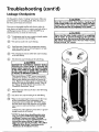
Leakage Checkpoints
A CAUTION
]
this manual_efore
checking the I
] water heater make sure the electric supply has been |
|turned "OFF', and never turn the electric supply/
[ "ON" before the tank is completely full of water.
]
Use this guide to check a "Leaking" water heater. Many suspected "Leakers" are not leaking tanks. Often the source of
the water can be found and corrected.
[
I Read
If you are not thoroughly familiar with electric codes, the
water heater, and safety practices, contact your local utility or
call Maytag Customer Service at 1-800-788-8899 for an
[
authorized servicer to check the water heater.
*Condensation may be seenon pipes in humid weather
or pipe connections may be leaking.
@
(_)
*The primary anode rod may be leaking.
Small amounts of water from temperature-pressure
relief valve may. be due to thermal expansion or high
water
(_)
@
pressure
in your
area.
*The temperature-pressure
at the tank fitting.
relief valve may be leaking
A_¢_
(D
The elements may be leaking at the tank fitting.
AWARNING
HAZARD OF ELECTRICAL SHOCK! Before
removing any access panels or servicing the
water heater, make sure the ele_rical supply
to the water heater is turned "OFF . Failure to
do this could result in DEATH, SERIOUS BODILY INJURY, OR PROPERTY DAMAGE.
Turn electrical power "OFF _, remove access panels
and fold hack insulation. If leaking around elements,
follow l_roper draining instructions and remove element. Keposition or replace gasket on element. Place
element into opening and tighten securely. Then follow "Filling the Water Heater" instructions in the
"Installation Instructions" section.
(_)
(_
A CAUTION
I
[ Never use this water heater unless it is completely
] full of water. To prevent damage to the tank and
[ heating element, the tank must be filled with water.
IThe water must flow from the hot water faucet
[ before turning "ON" power.
Water from drain valve
opened slightly.
may
be due to the valve being
*The drain valve may be leaking at the tank fitting.
water
OF on
*Water in the
heater bottom
the floor may
be from condensation, loose connections or the
temperature-pressure relief valve. DO NOT replace
the water heater until a _ inspection of all possible
water sources is made and necessary correcuve steps
taken.
Leakage from other appliances, water lines, or ground
seepage should also be checked.
*NOTE: To cheek where threaded portion enters
tank, insert cotton swab between jacket opening
and fitting. If cotton is wet, follow "Draining"
instructions in the "Service and Maintenance" section and then remove fitting. Put pipe dope or
teflon tape on the threads and repla_'e. Then follow
"Filling the Water Heater" instructions in the
alnstructions for Installation" section.
27
]
I
[
{
I
]
Repair Parts List
MAY'I'AG ELECTRICWATER HEATERS
MODEL NUMBERS
HE2930T
HE3930T
HE2940S
HE3940S
HE2940T
HE3940T
30
30
40
40
40
40
GALLON
GALLON
GALLON
GALLON
GALLON
GALLON
NOTE:
UPPER ELEMENT:
These
with 3800 watt elements.
water heaters are equipped
LOWER ELEMENT:
These water heaters are equipped
with factory installed convertible elements, which can be
operated at 3800 watts or 5500 watts. Convertible elements
are not offered as replacement parts.
If a replacement 3800 watt, 240 volt element is needed,
order part no. 66001106 replacement element. If, at the time
of
installation,
the part
waternumber
heater was
converted
to operateele-at
5500
watts, order
66001107
replacement
ment. (See model rating plate "IfConverted'_box).
[21
! 2o
3
I
28
Repair Parts List (cont'd)
MAYTAG ELECTRICWATER HEATERS
MODEL NUMBERS
HE2930T
HE3930T
HE2940S
HE3940S
HE2940T
HE3940T
KEY
NO.
30
30
40
40
40
40
GALLON
GALLON
GALLON
GALLON
GALLON
GALLON
HE293OT
1
2
3
4
Temperature-Pressure Relief Valve
Dip Tube Gasket
Dip Tube
Drain Valve
66001_010
66001269
66001065
66001015
66001010
66001269
66001065
66001015
I 66001010
66001269
66001052
66001015
5
Drain Valve Washer
_½Z'x'3/."x '/_"thick)*
Element Gasket
66001021
66001021
66001053
6
HE3930T
MODEL NUMBERS
HE2940S
HE3940S
PART NUMBERS
PART
DESCRIPTION
HE2940T
HE3940T
66001010
66001269
66001052
66001015
66001010
66001269
66001067
66001015
-66001010
66001269
66001067
66001015
I 66001021
66001021
66001021
66001021
66001053
66001053
66001053
66001053
66001053
66001055
66001054
66001007
66001055
66001054
--
SEE NOTE ON PAGE 28
66001055
66001055
66001054
66001054
66001007
--
66001055
66001054
66001007
66001055
66001054
--
7
8
9
10
Lower Element
Buss Bar Kit
Thermostat Bracket
2 Pole Thermostat
(Two Wire Lead Models)t
11
12
66001268
--
-66001008
66001268
--
-66001008
66001268
--
-66001008
13
14
Terminal Cover (Lower)
Lower Thermostat w/Hi Limit
(Three Wire Lead Models)t
Terminal Cover (Lower Three Wire)
Lower Access Panel
-66001245
66001272
66001245
-66001245
66001272
66001245
-66001245
66001272
66001245
15
16
17
18
19
Upper Access Panel
Terminal Cover (Upper)
Upper Thermostat w/Hi Limit
Upper Element
Element Gasket
66001199
66001064
66001009
66001199
66001064
66001009
66001199
66001064
66001009
66001199
66001064
66001009
66001053
66001053
66001199
66001199
66001064
66001064
66001009
66001009
SEE NOTE ON PAGE 28
66001053
66001053
66001053
66001053
20
21
22
#
Primary Anode
SecondaryAnode
Nipple
Manual
66001109
66001217
66001112
66001109
66001217
66001112
66001109
66001109
66001217
66001217
66001112
66001112
66001094
66001111
66001217
66001112
66001111
66001217
66001112
*Also available at most hardware stores.
tRefer to Wiring Diagram Section for verification.
#Not Illustrated
Now that you have purchased this water heater, should a
need ever exist for repair parts or service, simply call Maytag
Customer Service at 1-800-788-8899 for an authorized ser-
The model number of the water heater will be found on the
model rating plate located above the access panel.
vicer. Be sure to provide all pertinent facts when you call or
visit.
WHEN ORDERING
THE FOLLOWING
Model Number
Serial Number
REPAIR PARTS, ALWAYS GIVE
INFORMATION:
Part Description
Part Number
THIS IS A REPAIR PARTS LIST, NOT A PACKING LIST
29
Repair Parts List (cont'd)
MAY'rAG ELECTRICWATER HEATERS
MODEL NUMBERS
HE2940L
HE3940L
40 GALLON
40 GALLON
NOTE:
UPPER ELEMENT:
These
with 3800 watt dements.
water heaters
are equipped
LOWER ELEMENT: These water heaters are equipped
with factory installed convertible elements, which can be
operated at 3800 watts or 5500 watts. Convertible elements
are not offered as replacement parts.
If a replacement 3800 watt, 240 volt element is needed,
order part no. 66001106 replacement element. If, at the time
of installation, the water heater was converted to operate at
5500 watts, order part number 66001107 replacement element. (See model rating plate If Converted_box).
I
|22
21
s
30
02
2O
Repair Parts List (cont'd)
MAYTAG ELECTRICWATER HEATERS
MODEL NUMBERS
HE2940L
HE3940L
40 GALLON
40 GALLON
KEY
PART
NO.
1
DESCRIPTION
Temperature-Pressure Relief Valve
Dip Tube Gasket
Dip Tube
Drain Valve
Drain Valve Washer
_V_'x "/_"x V." thick)*
Element Gasket
Lower Element
BussBar Kit
Thermostat Bracket
2 Pole Thermostat
2
3
4
5
6
7
8
9
10
MODEL NUMBERS
HE2940L
HE3940L
PART NUMBERS
66001010
66001010
66001269
66001269
66001261
66001261
66001015
66001015
66001021
66001021
66001053
66001053
SEE NOTE ON PAGE 30
66001055
66001055
66001054
66001054
66001007
-66001268
--
-66001008
13
14
(Two Wire Lead Models)t
Terminal Cover (Lower)
Lower Thermostat w/Hi Limit
(Three Wire Lead Models)t
Terminal Cover (Lower Three Wire)
Lower Access Panel
-66001253
66001272
66001253
15
16
17
18
19
Upper AccessPanel
Terminal Cover (Upper)
Upper Thermostat w/Hi Limit
Upper Element
Element Gasket
66001199
66001199
66001064
66001064
66001009
66001009
SEE NOTE ON PAGE 30
66001053
66001053
20
21
22
#
Primary Anode
Secondary Anode
Nipple
Manual
66001052
66001052
66001217
66001217
66001112
66001112
66001094
11
12
*Also available at most hardware stores.
"?Refer to Wiring Diagram Section for verification.
#Not Illustrated
Now that you have purchased this water heater, should a
need ever exist for repair parts or service, simply call Maytag
Customer Service at 1-800-788-8899 for an authorized ser-
The model number of the water heater will be found on the
model rating plate located above the access panel.
vicer. Be sure to provide all pertinent facts when you call or
visit.
WHEN ORDERING
THE FOLLOWING
Model Number
Serial Number
REPAIR PARTS, ALWAYS GIVE
INFORMATION:
Part Description
Part Number
THIS IS A REPAIR PARTS LIST, NOT A PACKING LIST.
31
Repair Parts List (cont'd)
MAYTAG ELECTRICWATER HEATERS
MODEL NUMBERS
HE2950S
HE3950S
HE2950T
HE3950T
HE2966T
HE3966T
50
50
50
50
66
66
GALLON
GALLON
GALLON
GALLON
GALLON
GALLON
NOTE:
UPPER ELEMENT: These
with 3800 watt elements.
water heaters
are equipped
LOWER ELEMENT: These water heaters are equipped
with factory installed convertible elements, which can be
operated at 3800 watts or 5500 watts. Convertible elements
are not offered as replacement parts.
If a replacement
3800 watt, 240 volt element is needed,
order part no. 66001106 replacement element. If, at the time
of installation, the water heater was converted to operate at
5500 watts, order part numb_ 66001107 r_lacement element.(Seemodelratingplate
IfConverted
box).
I
I
21
1 22
I
0
2
20
Repair Parts List (cont'd)
MAYTAG ELECTRICWATER HEATERS
MODEL NUMBERS
HE2950S
HE3950S
HE29SOT
HE3950T
HE2966T
HE3966T
KEY
NO.
1
2
3
4
5
6
7
8
9
10
11
12
50
50
50
50
66
66
GALLON
GALLON
GALLON
GALLON
GALLON
GALLON
MODEL NUMBERS
HE2950T
HE3950T
PART NUMBERS
PART
DESCRIPTION
HE2950S
HE3950S
HE2966T
HE3966T
Temperature-Pressure Relief Valve
Dip Tube Gasket
Dip Tube
Drain Valve
Drain VaNeWasher
%f'x lY_"x ¼" thick)*
Element Gasket
Lower Element
BussBar Kit
Thermostat Bracket
2 Pole Thermostat
(Two Wire Lead Models)t
66001010
66001269
66001065
66001075
66001021
66001010
66001269
66001065
66001075
66001021
66001010
66001269
66001066
66001015
66001021
66001010
66001269
66001067
66001015
66001021
66001010
66001269
66001067
66001015
66001021
66001053
66001053
66001053
66001053
66001055
66001054
--
66001053
66001053
SEE NOTE ON PAGE 32
66001055
66001055
66001054
66001054
66001007
--
66001055
66001054
66001007
66001055
66001054
66001007
66001055
66001054
--
66001268
--
-66001008
66001268
--
-66001008
66001268
--
-66001008
-66001245
66001272
66001245
-66001245
66001272
66001245
-66001245
66001272
66001245
66001199
66001064
66001009
66001199
66001064
66001009
66001053
66001053
66001010
66001269
66001066
66001015
66001021
13
14
Terminal Cover (Lower)
Lower Thermostat w/Hi Limit
(Three Wire Lead Models)_
Terminal Cover (Lower Three Wire)
Lower Access Panel
15
16
17
18
19
Upper Access Panel
Terminal Cover (Upper)
UpperThermostatw/Hi
Limit
Upper Element
Element Gasket
66001199
66001064
66001009
66001199
66001064
66001009
66001053
66001053
66001199
66001199
66001064
66001064
66001009
66001009
SEE NOTE ON PAGE 32
66001053
66001053
20
21
Primary Anode
Secondary Anode
66001109
66001217
66001109
66001217
66001111
66001217
66001111
66001217
66001111
66001217
66001111
66001217
22
#
Nipple
Manual
66001112
66001112
66001112
66001112
66001094
66001112
66001112
*PAso av_lab[_ at most hzrdware sto_es.
J'Refer to Wiring Diagram Section for verification.
#Not Illustrated
Now that you have purchased this water beater, should a
need ever exist for repair parts or service, simply call Maytag
Customer Service at 1-800-788-8899 for an authorized ser-
The model number of the water heater will be found on the
model rating plate located above the access panel.
vicer. Be sure to provide all pertinent facts when you call or
visit.
WHEN ORDERING
THE FOLLOWING
Model Number
Serial Number
REPAIR PARTS, ALWAYS GIVE
INFORMATION:
Part Description
Part Number
THIS IS A REPAIR PARTS LIST, NOT A PACKING LIST.
33
Repair Parts List (cont'd)
MAYTAG ELECTRICWATERHEATERS
MAYTAG/STATE
PARTNUMBER CONVERSIONKEY
MAYTAG
STATE
66001007
9002437
66001008
9002436
66001009
9002435
66001010
9002403
66001011
9001609
66001012
9001608
_
66001014
66001013
66001015
66001021
66001052
66001053
66001054
66001055
66001064
66001065
66001066
66001067
66001068
66001075
66001094
66001105
66001106
66001107
66001109
66001111
66001112
66001199
66001217
66001245
66001252
66001253
66001261
66001268
66001269
66001272
ETC5X
ETC2X
9002401
9001584
9002059
9000308
9000309
9001591
9002438
9002432
9002416
9002058
9001453
9002648
0002916220-2
9002769
9000225
9000396
9001830
9001672
9000399
9000383
9000947
9001565
9001834
9001899
9001986
9002276
9002277
9002303
34
Notes
35
Warranty
FULL ONE YEAR WARRANTY
For One Year from the date of Original Retail Purchase, any part which fails in normal home use will be repaired or
replaced free of charge.
If a leak occurs in the Tank, a new water heater of the closest capacity and quality then available, will be replaced free
of charge.
The warranty of the replacement is the balance of the original water heater's Warranty.
LIMITED
PARTS WARRANTY
After the First year and through the Ninth Year from the date of Original Retail Purchase, any Parts which fail due
to a defect in materials or workmanship, wiU be replaced or repaired free of charge for the part itself, with the owner
paying all other costs, including labor, mileage and transportation.
If the water heater is subjected to commercial, institutional, industrial or non-residential use, the above warranty coverage for parts that are proved to be defective in material or workmanship is effective for one year from the date of the
Original Retail Purchase.
The warranty of the replacement is the balance of the original water heater's Warranty, or twelve months from the
date of the part(s) purchase, whichever comes first.
The warranty is limited to the original owner of the water heater.
LIMITED
TANK WARRANTYAGAINST
LEAKS
After the First Year and through the Ninth Year from the date of Original Retail Purchase, if a leak occurs in the
Tank, a new water heater of the closest capacity and quality then available, will be replaced free of charge for the water
heater, with the owner paying all other costs, including labor, mileage and transportation.
If the water heater is subjected to commercial, institutional, industrial or non-residential use, the above warranty coverage for tanks that are proven to be defective in material or workmanship is effective for two years from the date of
the Original Retail Purchase.
The warranty of the replacement is the balance of the original water heater's Warranty.
Please note: The Full and Limited Warranty applies only while this water heater is used in the United States of America.
The warranty is limited to the original owner of the water heater.
TO RECEIVE WARRANTY
SERVICE
To locate an authorized service company in your area contact the Maytag dealer from whom your appliance was purchased; or call Maytag Customer Service at the number listed below. Should you not receive satisfactory warranty
service, please call or write:
Maytag Customer Service
RO. Box 2370
Cleveland, TN 37320-2370
U.S.A. 1-800-788-8899
When contacting Maytag Customer Service be sure to provide the Model and Serial Number of your appliance, The
Name and Address of the Dealer from whom you purchased the appliance and the Date of Purchase.
MAYTAG WATER HEATERS ARE MANUFACTURED
AND THIS WARRANTY
STATE INDUSTRIES, INC., ASHLAND CITY, TN. MAYTAG IS A TRADEMARK
PORATION AND IS USED UNDER LICENSE TO STATE INDUSTRIES, INC.
01-02
PROVIDED BY
OF MAYTAG COR-
66001094
0002916220-2