1
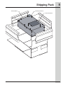
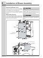
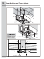
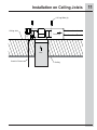
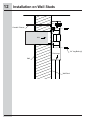
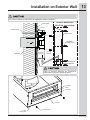
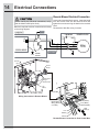
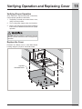
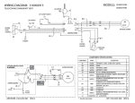
Installation Instructions
Remote Blower Assembly for Telescoping Downdraft Ventilation System
(1600cfm)
316902918 (April 2012)
2
Finding Information
Table of contents
Please read & save this guide
Finding Information .................................................2
Important Safety Instructions ..................................3
Shipping Pack.........................................................5
Dimensions .............................................................6
Planning..................................................................7
Installation of Blower Assembly ..............................8
Mount Main Housing to Structure ...........................9
Installation on Floor Joists ....................................10
Installation on Ceiling Joists .................................11
Installation on Wall Studs .....................................12
Installation on Exterior Wall ..................................13
Electrical Connections ..........................................14
Verifying Operation and Replacing Cover ............15
Warranty ...............................................................16
Thank you for choosing Electrolux, the new
premium brand in home appliances. These
Installation Instructions are part of our commitment
to customer satisfaction and product quality
throughout the service life of your new appliance.
This unit is intended for
domestic cooking ONLY.
We view your purchase as the beginning of a
relationship. To ensure our ability to continue
serving you, please use this page to record
important product information.
Questions?
For toll-free telephone support in the U.S. and
Canada:
1-877-4ELECTROLUX (1-877-435-3287)
For online support and Internet production information
visit http://www.electroluxappliances.com
INSTALLER:
LEAVE INSTRUCTIONS WITH
OWNER.
HOMEOWNER:
READ YOUR RETRACTABLE
VENTILATION SYSTEM USE
& CARE MANUAL. It contains
important safety information
for operating this appliance. It
also has many suggestions for
getting the best results from your
retractable ventilation system.
©2012 Electrolux Home Products, Inc.
All rights reserved. Printed in U.S.A.
Important Safety Instructions
What you need to know about safety instructions
Warning and Important Instructions appearing in this guide are not meant to cover all possible conditions
and situations that may occur. Common sense, caution and care must be exercised when installing,
maintaining or operating an appliance.
ALWAYS contact your dealer, distributor, service agent or manufacturer about problems or conditions
you do not understand.
Recognize Safety Symbols, Words, Labels
WARNING — Hazards or unsafe practices
which COULD result in severe personal injury
or death.
CAUTION — Hazards or unsafe practices which
COULD result in minor personal injury.
TO REDUCE THE RISK OF FIRE, ELECTRIC
SHOCK, OR INJURY TO PERSONS, OBSERVE
THE FOLLOWING:
• Installation work and electrical wiring must be
done by a qualified person(s) in accordance
with all applicable codes and standards,
including fire-rated construction codes and
standards.
• Sufficient air is needed for proper combustion
and exhausting of gases through the flue
(chimney) of fuel burning equipment to prevent
backdrafting. Follow the heating equipment
manufacturer’s guideline and safety standards
such as those published by the National
Fire Protection Association (NFPA), and the
American Society for Heating, Refrigeration
and Air Conditioning Engineers (ASHRAE), and
the local code authorities.
• When cutting or drilling into wall or ceiling, do
not damage electrical wiring and other hidden
utilities.
• Ducted fans must always be vented to the
outdoors.
• Use this unit only in the manner intended by the
manufacturer. If you have questions, contact
the manufacturer.
• Before servicing or cleaning unit, switch
power off at service panel and lock the service
disconnecting means to prevent power from
being switched on accidentally. When the
service disconnecting means cannot be locked,
securely fasten a prominent warning device,
such as a tag, to the service panel.
TO REDUCE THE RISK OF FIRE, ELECTRIC
SHOCK, OR INJURY TO PERSONS, OBSERVE
THE FOLLOWING (continued):
• Blower must not be installed in a ceiling
thermally insulated to a value greater than R40.
• Blower must not be installed in furnace
ductwork.
• To reduce the risk of fire, use only metal
ductwork.
TO REDUCE THE RISK OF A RANGE TOP
GREASE FIRE:
• Never leave surface units unattended at high
settings. Boilovers`cause smoking and greasy
spillovers that may ignite. Heat oils slowly on
low or medium settings.
• Always turn hood ON when cooking at high
heat or when cooking flaming foods.
• Clean ventilating fans frequently. Grease
should not be allowed to accumulate on fan or
filter.
• Use proper pan size. Always use cookware
appropriate for the size of the surface element.
3
4
Important Safety Instructions
TO REDUCE THE RISK OF INJURY TO
PERSONS IN THE EVENT OF A RANGE TOP
GREASE FIRE, OBSERVE THE FOLLOWING*:
• SMOTHER FLAMES with a close-fitting lid,
cookie sheet, or metal tray, then turn off
the burner. BE CAREFUL TO PREVENT
BURNS. If the flames do not go out
immediately, EVACUATE AND CALL THE FIRE
DEPARTMENT.
• NEVER PICK UP A FLAMING PAN - You may
be burned.
• DO NOT USE WATER, including wet dishcloths
or towels - a violent steam explosion will result.
• Use an extinguisher ONLY if:
A. You know you have a Class ABC
extinguisher, and you already know how to
operate it.
B. The fire is small and contained in the area
where it started.
C. The fire department is being called.
D. You can fight the fire with your back to an
exit.
* Based on “Kitchen Firesafety Tips” published by
NFPA.
• For general ventilating use only. Do not use to
exhaust hazardous or explosive materials and
vapors.
• To reduce risk of fire and to properly exhaust
air, be sure to duct air outside. Do not vent
exhaust air into spaces within walls or ceilings
or into attics, crawl spaces or garages.
• This blower assembly is approved for use with
the following Electrolux Telescoping Downdraft
Systems: EI30DD10KSA, EI36DD10KSA,
FH30DD50MSA and FH36DD50MSA only.
Use of this blower assembly with any other
product or in any other configuration is
hazardous and voids the product warranty.
NOTE
• Consult a licensed ventilation contractor or
qualified technician for proper installation of
exhaust ducting.
• Locate the cooking area for minimum cross
drafts - away from doors and windows, when
possible.
• Ducts must be of adequate size and duct runs
should be as short and straight as possible.
Where turns are necessary, keep turning radius
as large and smooth as possible.
• The ducting must be air tight. Use a minimum
of 2 sheet metal screws at every duct joint.
Then, seal the duct joints with a high quality
duct tape.
• In duct runs less than 10 equivalent straight
feet, the remote blower may interfere with the
cooktop burner performance due to the high
volume of air moved. An adjustable damper
(not included) should be installed in the
ducting system. The damper can be adjusted
so that proper ventilation and cooktop burner
performance is achieved.
• Installation of duct work should be carefully
planned if it is to go under a concrete slab floor.
The duct trench should be boxed to prevent
collapse from the wet cement. Be sure to allow
room to run the electrical wiring and conduit.
SAVE THESE INSTRUCTIONS FOR
FUTURE REFERENCES
Shipping Pack
Remote Blower
Mounting Hardware
Instruction Manual
5
6
Dimensions
Specifications and Dimensions
Remote Blower Dimensions
19-3/4"
(50.2 cm)
Electrical
Conduit
Connection
Main
Blower
Housing
19-5/8"
(49.8 cm)
16-15/16"
(43 cm)
2-15/16"
(7.5 cm)
9-13/16"
(24.9 cm)
10-5/16"
(26.2 cm)
8-3/16"
(20.8 cm)
Air Inlet
Duct 10”
6-15/16"
(17.6 cm)
12-13/16"
(32.5 cm)
30-5/8"
(77.8cm)
Blower
Cover
Ø 10"
(25.4 cm)
16"
(40.6 cm)
30"
(76.2 cm)
(4) Mount
Points
16"
(40.6 cm)
1-13/16"
(4.6 cm)
Discharge
Discharge
3-1/4" (8.3 cm)
4” (10.2 cm)
4-3/4” (12.1 cm)
Adjustable Discharge
14"
(35.6 cm)
Discharge
List of Included Parts for model
EI16DDPRKS:
• (1) Blower
• (4) 1/4” Lag Bolts
Hardware Needed (User Supplied)
• 14 AWG Romex Cable (Min. Size)
IMPORTANT
Local building codes must be followed in specifying
approved type and specification of ALL duct used.
IMPORTANT
Retain all packing and materials until the
telescoping downdraft and all components
have been installed.
NOTE
All dimensional tolerances are +1/16”, -0”
unless otherwise stated.
Before starting installation, remove the cover
from the Blower Main Housing. Check to see if
the blower wheel turns freely. Do not replace the
cover until the installation of the Blower Main
Housing is complete.
Planning
Installation Planning
Ductwork
A qualified technician must complete the installation
of this appliance.
Carefully check the location where the remote blower
is to be installed. The remote blower should be placed
for convenient access. Make certain that electrical
power can be provided in the selected location.
Use galvanized or aluminum duct in 8” / 10” round or
3¼”x14” / 4”x14” / 4¾”x14” size, or a combination of
both. PVC duct should be used if installing under a
poured concrete slab. Use the shortest and straightest
duct run possible.
Duct Tape Over
Seam and Screw
The Remote Blower can be installed in various
locations. These Installation Instructions will cover
some of the possibilities.
Page
1 - On Floor Joists ................................................10
Air Flow
2 - On Ceiling Joists .............................................11
3 - On Wall Studs .................................................12
Screw
4 - On Exterior Wall ..............................................13
NOTE
DO NOT mount the blower unit by the cover, or by
using any plumbing straps, or by any other method
than fastening with the lag bolts into solid structural
support members.
Local building codes must be followed in specifying
approved type and specification of ALL duct used.
Always use an appropriate roof or wall cap with
damper.
IMPORTANT
When mounting the unit, do not warp or bend
the housing, or mount in such a manner that the
connected ductwork causes the housing to flex.
Verify that the blower wheel spins freely.
When mounting the main blower housing, be sure
to fully engage the inlet collar of the blower with the
round duct inlet from the downdraft ventilation unit.
Secure the outlet to the exhaust duct.
Make sure that there is an appropriate damper
installed on the discharge ducting, per local code or
national building code, to prevent backflow of air.
All ductworks must be as installed as per local
codes.
To reduce risk of fire and to properly exhaust
air, be sure to duct air outside – Do not vent
exhaust air into spaces within walls or ceilings
or into attics, crawl spaces, or garages.
7
8
Installation of Blower Assembly
Remove the Blower Cover
Remove the Blower Cover from the Main Blower
Housing by removing the (16) silver hex head screws
from the Blower Cover. Retain the screws.
Remove the Wire box from the Main Blower Housing
by removing the 3 hex head screws. Retain the
screws.
DO NOT attach the Main Blower Housing directly
to wall board, ceiling panels, or other non-structural
materials. Refer to the section drawings on the
following pages to determine the proper mounting
orientation for the Main Blower Housing.
Mount Main Housing
The housing is designed to mount to joist or studs
on 16” centers. When mounting the Main blower
Housing, the (4) lag bolts must be attached to joists,
studs or other structural members.
DO NOT install the unit so that the unit is supported
by the Blower Cover. Damage to the Blower may
occur.
Blower
Cover
(16) Silver
Hex Head Screws
(3) Hex Head Screws
Wire Box
Mount Main Housing to Structure
When mounting the Main Blower Housing, the (4)
lag bolts must be attached to joists or studs, or
other structural members. When mounting the main
blower housing between floor joists or walls studs,
it is necessary to space the blower housing off the
floor or wall using a minimum 2x4 wood spacer. The
wood spacers should be properly secured to the joists
or studs. DO NOT secure the wood spacers to the
sub-floor or wall materials.
When mounting the main blower housing, be sure
to fully engage the inlet collar of the blower with the
round duct inlet from the downdraft ventilation unit.
Secure the outlet to the exhaust duct.
DO NOT mount the main blower housing directly to
sub-flooring or wall materials, this will not support
the remote blower housing correctly.
Before making any electrical connections, verify
that the blower wheel spins freely.
All duct connections should be sealed with duct tape
and secured with screws.
Connect the Romex cable from the downdraft
ventilation unit to the main blower housing.
Make the required electrical connections according
to the attached wiring diagram.
When mounting the unit, do not warp or bend
the housing, or mount in such a manner that the
connected ductwork causes the housing to flex.
Cross Brace
or Cleat
16”
(40.6 cm)
Over 16”
(40.6 cm)
Flooring
or Wall
Bracket
Inlet
Inlet
Joist
or Stud
Main
Blower
Housing
1/4” Lag Bolts
1/4” Lag Bolts
Mounting on Joists or Studs
Spaced 16”
Mounting Between Joists or Studs
Spaced More Than16”
9
10
Installation on Floor Joists
Inlet
Metal Duct
Discharge
Duct
Romex or
Metal Conduit
Floor
Joists
Main
Blower
Housing
Lag Bolts must be
attached to joists, studs
or structural members.
1/4” Lag Bolts (4)
Conduit / Romex
Flooring
Inlet
Floor Joist
1/4” Lag Bolts (4)
Discharge
Installation on Ceiling Joists
1/4” Lag Bolts (4)
Ceiling Joist
Discharge
Inlet
Conduit / Romex
Ceiling
11
12
Installation on Wall Studs
Conduit / Romex
Inlet
1/4” Lag Bolts (4)
Discharge
Wall
Wall Stud
Installation on Exterior Wall
The Outdoor Weather Kit WK-SP360 is required for outdoor installation.
Outdoor Weather Kit
Exterior Wall
WK-SP360 (not included)
Sealant
Conduit / Romex
Blower Cover
Zinc Plated
Phillips Screws
Inlet
Wall Stud
Discharge
4 3/4" x 14"
1/4” Lag
Bolts (4)
Note: Minimum 18”
from the ground.
Sealant
Refer to Outdoor Weather Kit Installation
Instructions for specific installation details.
3-1/4” Duct
4” Duct
4-3/4” Duct
Vent Slide
Bottom
Mouting Hole
Hex Head Screws
13
Electrical Connections
Remote Blower Electrical Connection
Loosen the 3 terminal block screws. Insert the leads
from the Romex cable into the terminal block and
tighten the screws securing the leads in the terminal
block.
Before making any electrical connections, verify
that the blower wheel spins freely.
Make the required electrical connections according
to the wiring diagram.
DOWNDRAFT
CONTROL BOX
Re-attach the Wire Box using 3 screws.
PIGTAIL
Capacitor
BLK
14
P8
P11
BLOWER HOUSING
BRN
BLK
BLK
WHT
BLU
GRN
GRN
Motor
120 VAC
CONTROL BOARD
FIELD WIRING
GND CONTROL
HOUSING
GND
Terminal
Block
Romex
Clamp
Romex Cable or
Wiring in
Metal Conduit
Line
(Black)
Neutral
Ground
(Green/Bare) (White)
Control Box
Wiring Connection in Remote Blower
Ground (Green)
Line (Black)
Blower Motor
Wiring (Romex
or conduit)
Neutral (White)
Line
Wire
Nuts (3)
Neutral
Ground
Remote Blower Connection to Vent Control Box
Verifying Operation and Replacing Cover
Verifying Proper Operation
After making the required electrical connections,
confirm proper operation of the blower.
1. Temporarily re-install the remote blower cover,
using 2 screws per side.
2. Turn on the power supply at the circuit breaker.
3. Refer to the Telescoping Down Draft Installation
Instructions for additional instructions on proper
operation.
DO NOT allow any objects to contact any moving
parts or electrical connections while verifying blower
operation.
Replace the Cover
Re-attach the Blower Cover to the Main Blower
housing using the (16) silver hex head screws.
(16) Silver
Hex Head Screws
15
16
Warranty
Your appliance is covered by a one year limited warranty. For one year from your original date of purchase, Electrolux will
repair or replace any parts of this appliance that prove to be defective in materials or workmanship when such appliance is
installed, used, and maintained in accordance with the provided instructions. In addition, the glass cooktop or radiant surface
element of your appliance (excluding built-in and free-standing range appliances) is covered by a two through five year
limited warranty. During the 2nd through 5th years from your original date of purchase, Electrolux will provide a replacement
glass cooktop or radiant surface element for your appliance which has proven to be defective in materials or workmanship
when such appliance is installed, used, and maintained in accordance with the provided instructions.
Exclusions
1.
2.
3.
4.
5.
6.
7.
8.
9.
10.
11.
12.
13.
14.
This warranty does not cover the following:
Products with original serial numbers that have been removed, altered or cannot be readily determined.
Product that has been transferred from its original owner to another party or removed outside the USA or Canada.
Rust on the interior or exterior of the unit.
Products purchased “as-is” are not covered by this warranty.
Products used in a commercial setting.
Service calls which do not involve malfunction or defects in materials or workmanship, or for appliances not in
ordinary household use or used other than in accordance with the provided instructions.
Service calls to correct the installation of your appliance or to instruct you how to use your appliance.
Expenses for making the appliance accessible for servicing, such as removal of trim, cupboards, shelves, etc.,
which are not a part of the appliance when it is shipped from the factory.
Service calls to repair or replace appliance light bulbs, air filters, water filters, other consumables, or knobs,
handles, or other cosmetic parts.
Labor or in-home service costs during the additional limited warranty periods beyond the first year from your
original date of purchase.
Pickup and delivery costs; your appliance is designed to be repaired in the home.
Surcharges including, but not limited to, any after hour, weekend, or holiday service calls, tolls, ferry trip charges,
or mileage expense for service calls to remote areas, including the state of Alaska.
Damages to the finish of appliance or home incurred during transportation or installation, including but not limited
to floors, cabinets, walls, etc.
Damages caused by: services performed by unauthorized service companies; use of parts other than genuine
Electrolux parts or parts obtained from persons other than authorized service companies; or external causes such
as abuse, misuse, inadequate power supply, accidents, fires, or acts of God.
DISCLAIMER OF IMPLIED WARRANTIES; LIMITATION OF REMEDIES
CUSTOMER’S SOLE AND EXCLUSIVE REMEDY UNDER THIS LIMITED WARRANTY SHALL BE REPAIR OR
REPLACEMENT AS PROVIDED HEREIN. CLAIMS BASED ON IMPLIED WARRANTIES, INCLUDING WARRANTIES
OF MERCHANTABILITY OR FITNESS FOR A PARTICULAR PURPOSE, ARE LIMITED TO ONE YEAR OR THE
SHORTEST PERIOD ALLOWED BY LAW, BUT NOT LESS THAN ONE YEAR. ELECTROLUX SHALL NOT BE LIABLE
FOR CONSEQUENTIAL OR INCIDENTAL DAMAGES SUCH AS PROPERTY DAMAGE AND INCIDENTAL EXPENSES
RESULTING FROM ANY BREACH OF THIS WRITTEN LIMITED WARRANTY OR ANY IMPLIED WARRANTY. SOME
STATES AND PROVINCES DO NOT ALLOW THE EXCLUSION OR LIMITATION OF INCIDENTAL OR CONSEQUENTIAL
DAMAGES, OR LIMITATIONS ON THE DURATION OF IMPLIED WARRANTIES, SO THESE LIMITATIONS OR
EXCLUSIONS MAY NOT APPLY TO YOU. THIS WRITTEN WARRANTY GIVES YOU SPECIFIC LEGAL RIGHTS. YOU
MAY ALSO HAVE OTHER RIGHTS THAT VARY FROM STATE TO STATE.
If You Need Service
Keep your receipt, delivery slip, or some other appropriate payment record to establish the warranty period should service
be required. If service is performed, it is in your best interest to obtain and keep all receipts. Service under this warranty
must be obtained by contacting Electrolux at the addresses or phone numbers below.
This warranty only applies in the USA, Puerto Rico and Canada. In the USA and Puerto Rico, your appliance is warranted
by Electrolux Major Appliances North America, a division of Electrolux Home Products, Inc. In Canada, your appliance
is warranted by Electrolux Canada Corp. Electrolux authorizes no person to change or add to any obligations under this
warranty. Obligations for service and parts under this warranty must be performed by Electrolux or an authorized service
company. Product features or specifications as described or illustrated are subject to change without notice.
USA
1.800.944.9044
Electrolux Home Products, Inc.,
10200 David Taylor Drive
Charlotte, NC 28262
Canada
1-800-265-8352
Electrolux Canada Corp.
5855 Terry Fox Way
Mississauga, Ontario, Canada L5V 3E4