1
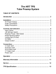
TubeFire 8™ 8 CHANNEL TUBE MIC-PREAMP SYSTEM USER’S GUIDE IMPORTANT SAFETY INSTRUCTIONS – READ FIRST This symbol, wherever it appears, alerts you to the presence of uninsulated dangerous voltage inside the enclosure. Voltage that may be sufficient to constitute a risk of shock. This symbol, wherever it appears, alerts you to important operating and maintenance instructions in the accompanying literature. Please read manual. Read instructions: Retain these safety and operating instructions for future reference. Heed all warnings printed here and on the equipment. Follow the operating instructions printed in this user guide. Do not open: Aside from four vacuum tubes, there are no user serviceable parts inside. Refer any service work to qualified technical personnel only. Power sources: Only connect the unit to mains power of the type marked on the rear panel. The power source must provide a good ground connection. Power cord: Use the power cord with sealed mains plug appropriate for your local mains supply as provided with the equipment. If the provided plug does not fit into your outlet consult your service agent. Route the power cord so that it is not likely to be walked on, stretched or pinched by items placed upon or against. Grounding: Do not defeat the grounding and polarization means of the power cord plug. Do not remove or tamper with the ground connection on the power cord. Ventilation: Do not obstruct the ventilation slots or position the unit where the air required for ventilation is impeded. If the unit is to be operated in a rack, case or other furniture, ensure that it is constructed to allow adequate ventilation. Moisture: To reduce the risk of fire or electrical shock do not expose the unit to rain, moisture or use in damp or wet conditions. Do not place a container of liquid on it, which may spill into any openings. Heat: Do not locate the unit in a place close to excessive heat or direct sunlight, as this could be a fire hazard. Locate the unit away from any equipment, which produces heat such as: power supplies, power amplifiers and heaters. Environment: Protect from excessive dirt, dust, heat, and vibration when operating and storing. Avoid tobacco ash, drink spillage and smoke, especially that associated with smoke machines. Handling: To prevent damage to the controls and cosmetics avoid rough handling and excessive vibration. Protect the controls from damage during transit. Use adequate padding if you need to ship the unit. To avoid injury to yourself or damage to the equipment take care when lifting, moving or carrying the unit. Servicing: Switch off the equipment and unplug the power cord immediately if it is exposed to moisture, spilled liquid, objects fallen into opening, or the power cord or plug becomes damaged during a lightning storm or if smoke odor or noise is noted. Refer servicing to qualified technical personnel only. Installation: Install the unit in accordance with the instructions printed in the user guide. 1 The ART TubeFire 8 8 Channel Tube Mic-Pre System IMPORTANT SAFETY INSTRUCTIONS – READ FIRST ...............................................1 INTRODUCTION..........................................................................................................4 INSTALLATION...........................................................................................................4 AC Power Hookup.................................................................................................................................................................................. 4 Analog Audio Connections ..................................................................................................................................................................... 4 Firewire (IEEE 1394) (Sony iLINK®) Connections .................................................................................................................................. 5 CONTROLS and JACKS ..............................................................................................5 FRONT PANEL ...................................................................................................................................................................................... 5 Instrument Input ..................................................................................................................................................................................... 6 Gain Control ........................................................................................................................................................................................... 6 Pad Switch ............................................................................................................................................................................................. 6 +48V Switches........................................................................................................................................................................................ 6 Phase Switch.......................................................................................................................................................................................... 6 Low Cut Switch....................................................................................................................................................................................... 6 LED Meter .............................................................................................................................................................................................. 6 Output Control ........................................................................................................................................................................................ 6 Output Source Switches ......................................................................................................................................................................... 6 Headphone / Line Mixer ......................................................................................................................................................................... 7 Mix Level Control.................................................................................................................................................................................... 7 Power Switch.......................................................................................................................................................................................... 7 REAR PANEL......................................................................................................................................................................................... 8 Balanced Input Jacks – XLR & 1/4” TRS Combo Jacks ......................................................................................................................... 8 Balanced Output Jacks........................................................................................................................................................................... 8 Output Level Switch ............................................................................................................................................................................... 8 Wordclock Input and Thru Jacks ............................................................................................................................................................ 8 Firewire Jacks ........................................................................................................................................................................................ 8 HARDWARE OPERATION............................................................................................9 How to adjust the controls for the lowest noise ...................................................................................................................................... 9 How to set the Output Level switch (on the rear panel) .......................................................................................................................... 9 How to use the Headphone / Line Mixer Output..................................................................................................................................... 9 PC SOFTWARE OPERATION.....................................................................................11 Installing the Windows PC driver.......................................................................................................................................................... 11 Using the Windows PC driver panel ..................................................................................................................................................... 11 Changing the name of your TubeFire 8™ with a Windows PC............................................................................................................. 11 Changing the sample rate .................................................................................................................................................................... 12 Adjusting system latency with a Windows PC ...................................................................................................................................... 14 Using the wordclock input with a Windows PC..................................................................................................................................... 15 Mac SOFTWARE OPERATION ..................................................................................16 Changing the sample rate with a Mac .................................................................................................................................................. 16 Using the wordclock input with a Mac .................................................................................................................................................. 17 Creating an Aggregate Device with a Mac ........................................................................................................................................... 18 APPLICATIONS.........................................................................................................19 Adding more TubeFire 8™ units to your system .................................................................................................................................. 19 Typical applications .............................................................................................................................................................................. 20 WARRANTY INFORMATION .....................................................................................21 SERVICE ...................................................................................................................22 TubeFire 8™ SPECIFICATIONS ................................................................................23 2 List of Figures FIGURE 1 - Input Channel ......................................................................................................................................................................... 5 FIGURE 2 - Output Mix/Headphone section............................................................................................................................................... 7 FIGURE 3 - Rear Panel.............................................................................................................................................................................. 8 FIGURE 4 - Block Diagram ...................................................................................................................................................................... 10 FIGURE 5 - Renaming your TubeFire 8™................................................................................................................................................ 11 FIGURE 6 - Control Panel Sample Rate .................................................................................................................................................. 12 FIGURE 7 – Cubase Sample Rate Selection ........................................................................................................................................... 12 FIGURE 8 - Sample Rate Indication......................................................................................................................................................... 13 FIGURE 9 - ART ASIO Driver buffer depth adjustment ............................................................................................................................ 14 FIGURE 10 –Wordclock connections ....................................................................................................................................................... 15 FIGURE 11 - Audio/MIDI Setup Utility...................................................................................................................................................... 16 FIGURE 12 - ART Panel program ............................................................................................................................................................ 17 FIGURE 13 - Audio/MIDI Setup - Audio pull-down menu ......................................................................................................................... 18 FIGURE 14 - Aggregate Device Editor window ........................................................................................................................................ 18 FIGURE 15 - ART Card control panel for multiple TubeFire 8™ units ..................................................................................................... 19 3 INTRODUCTION The TubeFire 8™ is the answer to your recording and computer interface needs. Eight high quality vacuum tube microphone preamps are packaged in a single rack high package. Our second generation discrete class– A mic preamps provide clean quiet gain while maintaining incredible transparency. Either the analog mic preamps, or the internal high quality D/A converters can drive the eight balanced outputs, selectable in banks of two channels at a time. Connect to a PC or Mac with the Firewire interface and give your computer eight analog inputs and eight analog outputs. The eight outputs are also summed into the headphone output thereby providing a mono or stereo mixer function for low latency input monitoring, foldback monitoring from the CPU, and a mixed output of both. Every input channel offers balanced 1/4" phone or XLR input, 70dB of gain, Pad switch, Low-Cut filter switch, Phase Invert switch, and a wide range LED meter to monitor the preamp output levels. The clip indicators monitor mic-preamp peak levels. Each channel has a variable output level control allowing you to use the tube stage for warming effects and adjust to various system levels, or just to completely mute the channel. INSTALLATION The TubeFire 8 may be used in a wide variety of applications and environments. In a rack-mountable, allsteel enclosure, the unit is designed for continuous professional use. Mounting location is not critical. However, for greater performance reliability we recommend that you not place the unit on top of power amps or other sources of heat, or strong magnetic fields. The tube circuitry needs about a minute to “warm up” and stabilize from a cold power up. AC Power Hookup The TubeFire 8 has an internal power supply. Only connect the unit to mains power of the type marked on the rear panel. The power source must provide a good ground connection, and the ground pin on the mains plug should never be defeated. Analog Audio Connections Audio connections to and from the TubeFire 8 are: Rear balanced combo input: [XLR] Pin 2 = Hot (+), Pin 3 = Cold (-), Pin 1 = Ground [1/4”] Tip = Hot (+), Ring = Cold (-), Sleeve = Ground Rear balanced 1/4” output: Tip = Hot (+), Ring = Cold (-), Sleeve = Ground Front 1/4” input: Tip = Hot (+), Ring = Cold (-), Sleeve = Ground 4 Firewire (IEEE 1394) (Sony iLINK®) Connections The TubeFire 8 has two 6 pin Firewire ports located on the rear panel. Both ports are identical, and can be used interchangeably. Use a quality Firewire cable to connect the TubeFire 8 to your computer. NOTE: Make all connections with both the Computer and TubeFire 8 powered off. First power on the computer, and after the system OS has fully loaded, then power on the TubeFire 8. While Firewire is considered to be a “hot swappable” technology, experience indicates that to avoid system errors and lockups, it is best to not disconnect and connect the Firewire cable while the AC power is on. Multiple TubeFire 8 units can be daisy-chained by using the ports on the rear panel, but care should be taken to minimize the number of TubeFire 8 units placed on each Firewire buss due to bandwidth limits. The TubeFire 8 utilizes Firewire 400 which handles 400Mbits/sec. Depending on the number of units running, you may notice limits in sample rate and total channel count. Adjust your system configuration accordingly. Individual cable lengths should be limited to 4.5m (14.76 ft.) maximum. Shorter is better. CONTROLS and JACKS FRONT PANEL FIGURE 1 - Input Channel 5 Instrument Input The 1/4” TS jack on the front panel provides a high impedance unbalanced input, and when used, automatically switches off the mic pre-amp. (The rear combo jack’s 1/4” TRS balanced input is lower impedance and is part of the mic pre-amp. The rear jack is not intended to be used with high impedance microphones or instruments.) NOTE: The PAD switch is disabled and does NOT affect the gain when using the Instrument input. Gain Control This control adjusts both the mic pre-amp gain as well as the instrument input gain. The gain markings apply to the mic pre-amp without the Pad switch depressed. (The instrument input gain is lower than the markings.) Please refer to the HARDWARE OPERATION section to learn how to optimize the gain control for low noise operation. Pad Switch This switch reduces the mic pre-amp gain to prevent clipping when high-level microphone or line level signals are applied to the rear panel XLR / 1/4” TRS combo jack input. This switch does NOT affect the instrument input. +48V Switches These switches provide phantom power to each set of four XLR inputs. Use phantom power only when the microphone you are using requires it. Doing so will extend the life of the TubeFire 8 as well as reduce the possibility of a shock hazard. Phase Switch This switch selects the output phase of the channel. There is a 180 degree phase inversion through the channel when the switch is lit. Low Cut Switch This switch inserts a 100Hz 6dB/Oct. Low-Cut filter into the signal path. The filter is designed to remove rumble, pops, and wind noise, yet still sound natural. LED Meter The four segment LED meter indicates the signal level at the input of the A/D converter. In addition to monitoring the A/D level, the CLIP LED monitors all of the gain stages within the preamp channel for clipping. Output Control The output control provides gain or attenuation to adjust to a variety of system operating levels. This control sets the level sent to the A/D converter (as well as to the output jacks if selected by the output source switches). Output Source Switches The Output Source switches select the signal sent to the output jacks and the Headphone output. Depressing a switch selects a pair of preamp outputs as the source for the corresponding output jacks as well as selecting the source for the headphone output mixer. 6 FIGURE 2 - Output Mix/Headphone section Headphone / Line Mixer All of the sources selected for the output jacks of the TubeFire 8™ are mixed together to provide a signal for the Headphone/Line Mixer Output. Use the Output Source switches to select which channels are from the mic preamps and which channels are from the computer in the headphone output mix. You can use this function to check the operation of the input channels as well as for multi-tracking punch-ins. NOTE: Signals sourced directly from the TubeFire 8™ preamps have zero latency whereas signals from the computer may have a finite amount of latency depending on the computer and software set-up. Mix Level Control The Mix Level control adjusts the output level present at the headphone jack. This control mutes the output when centered at 12 o’clock. Choose a stereo mix by turning clockwise or a mono mix by turning counterclockwise. The stereo mix has odd numbered channels in the left channel and even numbered channels in the right. You can use the headphone output as a stereo line output as well as for driving headphones. Power Switch This switch controls and indicates that the unit is powered up and operational. When dimly lit, it indicates a low power source or an internal problem. 7 REAR PANEL Balanced Input Jacks – XLR & 1/4” TRS Combo Jacks These balanced inputs are used for both microphone and line level signals. The gain sensitivity is identical for both the XLR and 1/4” TRS jacks, however the XLR input impedance is 6.4K Ohms and the 1/4” TRS input impedance is 20K Ohms. The front panel Pad switch varies the sensitivity of both inputs. Balanced Output Jacks Each channel has a low impedance 1/4” TRS balanced jack. Output Level Switch This switch optimizes the output level of the rear output jacks with your system operating level. Depress the switch when connected to +4dB systems. In this case the maximum output is +22dBV when the digital level equals 0 VU. When the switch is in the “out” position, the output levels are optimized for –10dBV systems. One way to determine how this switch should be set is to send audio through the TubeFire 8™ from a computer and run it into a line input on a mixer or signal processor. Check the meters on the mixer or signal processor to see if the level appears to be too high (clipping) or too low (barely showing any indication on the meters). Set the Output Level switch so that the level meters in the external gear do not indicate excessive clipping yet still provide good full-scale (or near full scale) deflection. FIGURE 3 - Rear Panel Wordclock Input and Thru Jacks The Wordclock input is used to externally sync the TubeFire 8™ to a master clock source. The BNC Wordclock Input jack is connected directly to the BNC Wordclock Thru jack, providing the ability to loop through the TubeFire 8™ and connect other devices to the wordclock sync source, saving the use of a BNC T– adapter. The input is high impedance thus leaving the wordclock connection unterminated. (A 75 Ohm BNC terminator should be used on the Wordclock Thru jack if the Wordclock Input jack is used only by itself.) Firewire Jacks The Firewire jacks are interchangable and allow both connection to your computer and to other Firewire devices including additional TubeFire 8™ units. 8 HARDWARE OPERATION How to adjust the controls for the lowest noise Start with the GAIN and OUTPUT knobs centered, and the Pad switch IN. This provides about 20dB of gain. Increase the Gain control until the Clip LED in the meter just barely comes on during the loudest peaks in level, and then back off the control slightly from that point. (The Clip LED can come on occasionally at most.) If there is not enough level with the Gain control set fully clockwise, back off the gain to 12 o’clock and place the Pad switch in the out position. Adjust the gain control as above. Adjust the Output control until the -10 light is on most of the time during loud passages. Increasing the input gain and decreasing the Output level control can add more tube warmth. Remember, that the Clip LED looks at both the preamp input and output peaks, whereas the -10, -20, -30 LED indicators only look at the output level which feeds to the A/D converter. How to set the Output Level switch (on the rear panel) Setting this switch correctly can lower the noise in the signal chain by optimizing the operating levels between the TubeFire 8™ and external gear. One way to determine how this switch should be set is to send audio through the TubeFire 8™ from a computer and run it into a line input on a mixer or signal processor. Check the meters on the mixer or signal processor to see if the level appears to be too high (clipping) or too low (barely showing any indication on the meters). Set the Output Level switch so that the level meters in the external gear do not indicate excessive clipping yet still provide good full-scale (or near full scale) deflection. How to use the Headphone / Line Mixer Output The TubeFire 8™ has eight D/A outputs that return audio from the computer and are assignable to the headphone output through the Output Source switches. This is done in pairs to support stereo operation. When a switch is in the OUT position, the corresponding channel pair of D/A’s (audio from computer) is selected to be mixed into the headphone output. When depressed, the corresponding channel pair of analog tube preamp outputs is mixed into the headphone output. First, determine which D/A’s to use as a source from the computer. A good start would be to use channels 7 & 8, since channels 1 & 2 are the most flexible for use as inputs. Make sure that the CHAN. 7 - 8 Output Source switches are in the OUT position. Next, decide which inputs you wish to monitor, and depress these switches. You can turn down the Output level controls on the unused channels. Make sure to select the Record Arm switches in your recording software for the channels that you want to record. Remember that the Output Level controls on each preamp affect the signal levels sent to the computer. To vary the balance in the mix between the pre-computer and post-computer audio, adjust the volume level from the computer (Channels 7 & 8 output levels on the computer program in this example). When the mix balance is set, adjust the Mix Level output knob for level as well as a mono or stereo mix. If 1 using a mono source (a vocal for instance) you can run mono mode to pan the vocal in the center of the mix. 1 You can maintain a stereo mix in this example by patching the analog output of channel 1 into the input of channel 2 and adjust its gain until the analog input is panned in the center. This assumes Channel 2 is unused of course! 9 FIGURE 4 - Block Diagram 10 PC SOFTWARE OPERATION Installing the Windows PC driver (Check at www.artproaudio.com for any driver updates.) Run SETUP.EXE on the driver disk to install the ART Firewire Driver. The installer will prompt for the destination directory. We suggest using the defaults. Connect the TubeFire 8™ to the computer’s Firewire port ONLY when prompted, NOT before. An icon will be placed on your desktop as well as in your STARTUP folder. The ART Driver will run every time you start your computer unless you remove the ART Driver icon from your STARTUP folder. You will need to run the driver if you wish to use the TubeFire 8™ with any recording software. Using the Windows PC driver panel You can adjust the sample rate, optimize the latency, select Wordclock as a timing source, check the status of the unit and even re-name your TubeFire 8™ using the ART Card Control Panel. Any changes you make will be recorded in the non-volatile flash memory of the TubeFire 8™ maintaining your settings even after loosing power. It is normal for the unit to mute audio and report “trying to lock” during any of these changes. This may last for a few seconds as the data is written to memory. Changing the name of your TubeFire 8™ with a Windows PC You can re-name the TubeFire 8™ in the Device Name column to more easily identify it in your recording software. Double click on the text and then type in something more descriptive than the default name as in FIGURE 5. FIGURE 5 - Renaming your TubeFire 8™ The information is saved in the flash memory of the TubeFire 8™ and will be there for the PC driver even after the unit is powered off. (NOTE: The renaming function is not available for Mac operation.) 11 Changing the sample rate STEP ONE: Open the ART Card Control panel on a PC, to modify the sample rate setting. FIGURE 6 - Control Panel Sample Rate STEP TWO: Change the sample rate setting in the recording software. In Cubase, this is done under the PROJECT tab in the PROJECT SETUP dialog. See FIGURE 7 for an example. FIGURE 7 – Cubase Sample Rate Selection 12 Changing the sample rate may lead to other issues, including audio dropouts. Monitor the ASIO Drop Outs for 10 - 20 seconds to assure that the number remains at zero. If they are NOT zero, then increase the buffer length until the ASIO Drop Outs number reduces to zero. NOTE: The front panel Sample Rate display on the TubeFire 8™ is a histogram. FIGURE 8 shows the display lit for a 48KHz sample rate. This makes reading the display much easier at a distance. ALL of the lights are lit when the unit is set to 96KHz. FIGURE 8 - Sample Rate Indication 13 Adjusting system latency with a Windows PC Adjusting the buffer depth varies the latency of the computer system used together with the TubeFire 8™. Typical recording software programs utilize either WDM or ASIO drivers. Adjusting the buffer depth control to the left will reduce the buffer size and therefore reduce the latency. The actual time readout is for one buffer. Most programs use at least two or three buffers (one for input, one for output, plus some finite number for signal processing inside the program). Depending on which driver you are using, click and hold either the WDM the ASIO slider knob until it is in the desired position. The numerical readout to the right of the slider indicates the buffer length in both time and samples. Once the adjustment is done, click the appropriate Apply button to make the change active. There will be a slight delay as the settings are updated. NOTE: The CuBase LE recording software package, which is included with the TubeFire 8™, uses the ASIO driver as shown below. FIGURE 9 - ART ASIO Driver buffer depth adjustment Too short of a buffer depth setting will create audible drop outs (digital data gaps). Monitor the ASIO Drop Outs for 10 - 20 seconds to assure that the number remains at zero. If they are NOT zero, then increase the buffer length until the ASIO Drop Outs number reduces to zero. 14 Using the wordclock input with a Windows PC The TubeFire 8™ can be used in both simple and complex systems. The simplest system would consist of the TubeFire 8™ and a computer. As multiple digital devices are added to a system, master/slave sample rate timing issues degrade audio performance. Using a single master wordclock to synchronize all of the digital processing units reduces timing offset, and eliminates any time drift between the units thereby improving audio quality and reliability. Wordclock should to be applied to EVERY unit in the audio chain including soundcards. First, assure that the TubeFire 8™ is connected to a good wordclock generator running at the intended sample rate. Multiple TubeFire 8™ units can be daisy-chained by looping the wordclock signal from unit to unit, using the Wordclock Input and Thru jacks of each TubeFire 8™, and then placing a single 75 Ohm BNC terminator on the Wordclock Thru jack of the last device in the chain (furthest away from the wordclock generator). Alternatively multiple TubeFire 8™ units can be connected directly to the separate outputs of a wordclock generator in which case each TubeFire 8™ will require a 75 Ohm BNC terminator placed on its respective Wordclock Thru jack. (Because the TubeFire 8™ is not an internally terminated device.) Next, run the ART Card Control Panel and set the sample rate to the expected sample rate coming from the external wordclock generator. Finally, click the Sync Mode button in the ART Card Control Panel that reads “External - Word”. The TubeFire 8™ is now slaved to the Wordclock generator. If the sample rate of the generator is changed, make sure to match this setting change in the ART Card Control Panel as well. The final step is to change the sample rate in Cubase (or whatever recording program you are using). FIGURE 10 –Wordclock connections 15 Mac SOFTWARE OPERATION Changing the sample rate with a Mac Run the AUDIO/MIDI setup utility to change the sample rate. Select properties for the device labeled “ART Firewire nnnn” (the “nnnn” refers to a unique serial number for each TubeFire 8™). Under the Audio Input section use the Format pull-down menu to select the desired sample rate. Note that the Audio Input and Audio Output Format settings track each other. (The various volume sliders, mutes, and thru radio buttons are all grayed out and disabled. These functions are typically controlled in the recording software program.) FIGURE 11 - Audio/MIDI Setup Utility 16 Using the wordclock input with a Mac The TubeFire 8™ can be used in both simple and complex systems. The simplest system would consist of the TubeFire 8™ and a computer. As multiple digital devices are added to a system, master/slave sample rate timing issues degrade audio performance. Using a single master wordclock to synchronize all of the digital processing units reduces timing offset, and eliminates any time drift between the units thereby improving audio quality and reliability. Wordclock should to be applied to EVERY unit in the audio chain including soundcards. First, make sure that the TubeFire 8™ is connected to a good wordclock generator running at the intended sample rate. Multiple TubeFire 8™ units can be daisy-chained by looping the wordclock signal from unit to unit, using the Wordclock Input and Thru jacks of each TubeFire 8™, and then placing a single 75 Ohm BNC terminator on the Wordclock Thru jack of the last device in the chain (furthest away from the wordclock generator). Alternatively multiple TubeFire 8™ units can be connected directly to separate outputs of the wordclock generator in which case each TubeFire 8™ will require a 75 Ohm BNC terminator placed on the Wordclock Thru jack of each TubeFire 8™. (Because the TubeFire 8™ is not an internally terminated device.) Refer to FIGURE 10 for examples of using and terminating Wordclock. Next, run the ART Panel for Macintosh utility (included on the ART software disk or downloadable at www.artproaudio.com) and set the SYNC MODE to External. Next click the AUDIO / MIDI SETUP button and use the Format pull-down menu to select the expected sample rate coming from the external wordclock generator. The TubeFire 8™ is now slaved to the Wordclock generator. If the sample rate of the generator is changed, make sure to match this setting change in the ART Card Control Panel as well. The final step is to change the sample rate in Cubase (or whatever recording program you are using). FIGURE 12 - ART Panel program 17 Creating an Aggregate Device with a Mac Control of multiple audio devices on a Mac is performed by creating a single Aggregate Device. What follows is an example combining two TubeFire 8™ units into a single Aggregate Device, but it could be two completely different digital audio products. First, run the Audio/MIDI Setup utility. Pull down the Audio menu and run the Aggregate Device Editor. FIGURE 13 - Audio/MIDI Setup - Audio pull-down menu Next, Click the “+” (Add) button to create a new device. Select the audio devices that will comprise the new aggregate device by clicking the “Use” buttons. At this point you can re-name the Aggregate Device by double clicking the name. We used the name “ TubeFire 8™ pair” in our example in Figure 14. Click Done and you can use the new device! FIGURE 14 - Aggregate Device Editor window 18 APPLICATIONS Adding more TubeFire 8™ units to your system The TubeFire 8™ is designed to allow you to expand the number of inputs and outputs on your system by adding more TubeFire 8™ units. The bandwidth of the Firewire buss limits the number of units that can be added to a system. This is further determined by the selected sample rate. 88.2KHz or 96KHz sample rates – maximum of two TubeFire 8™ units (16 channels). 44.1KHz or 48KHz sample rates – maximum of four TubeFire 8™ units (32 channels). 2 The first step is to connect each unit to the Firewire buss. Refer to the FIGURE 3. Multiple units can be daisychained (unit to unit) by utilizing the ”To Computer” and “Expansion” Firewire ports on the TubeFire 8™ units. Alternatively each TubeFire 8™ can be connected directly to the computer if there are enough available Firewire ports. Use the ART Card Control Panel (Windows PC) or the AUDIO/MIDI Setup utility (Mac) to set up your system for multiple TubeFire 8™ units. FIGURE 15 - ART Card control panel for multiple TubeFire 8™ units 2 These numbers are based on 100Mb/Sec. Firewire Rates. The TubeFire 8™ is capable of 400Mb/s, but there are a number of factors that may limit your system to the 100Mb/Sec. rate. 19 Optionally rename the units in the ART Card Control Panel (Windows PC) or create an “Aggregate Device” (Mac) to simplify the ID of each unit. See the Mac Software Operation section for instructions on creating an Aggregate Device. Note that the order of devices listed is arranged by each unit’s SERIAL NUMBER. The order is fixed and cannot be changed. We recommend using external wordclock to maintain the highest audio quality when using multiple devices. Wordclock should to be applied to EVERY unit in the audio chain including soundcards. The wordclock signal can be looped through the TubeFire 8™ units using their rear panel wordclock Input and Thru connectors, with a 75 Ohm BNC terminator applied to the last unit in the chain. Typical applications Home and Commercial Recording Studios Live Sound Recording Broadcast/Radio/TV - Multi-channel playback and recording 20 WARRANTY INFORMATION Limited Warranty: Applied Research and Technology will provide warranty and service for this unit in accordance with the following warrants: Applied Research and Technology, (A R T) warrants to the original purchaser that this product and the components thereof will be free from defects in workmanship and materials for a period of three years from the date of purchase. Applied Research and Technology will, without charge, repair or replace, at its option, defective product or component parts upon prepaid delivery to the factory service department or authorized service center, accompanied by proof of purchase date in the form of a valid sales receipt. Exclusions: This warranty does not apply in the event of misuse or abuse of the product or as a result of unauthorized alterations or repairs. This warranty is void if the serial number is altered, defaced, or removed. A R T reserves the right to make changes in design or make additions to or improvements upon this product without any obligation to install the same on products previously manufactured. A R T shall not be liable for any consequential damages, including without limitation damages resulting from loss of use. Some states do not allow limitations of incidental or consequential damages, so the above limitation or exclusion may not apply to you. This warranty gives you specific rights and you may have other rights, which vary, from state to state. For units purchased outside the United States, an authorized distributor of Applied Research and Technology will provide service. 21 SERVICE The following information is provided in the unlikely event that your unit requires service. 1) Be sure that the unit is the cause of the problem. Check to make sure the unit has the proper power supplied, all cables are connected correctly, and the cables themselves are in working condition. 2) If you find the unit to be at fault, write down a complete description of the problem, including how and when the problem occurs. 3) Contact our Customer Service Department at (716) 297-2920 for your Return Authorization number or questions regarding technical assistance or repairs. Customer Service hours are 9:00 AM to 5:00 PM Eastern Standard Time, Monday through Friday. 4) Pack the unit in its original carton or a reasonable substitute. The packing box is not recommended as a shipping carton. Put the packaged unit in another box for shipping. Print the RA number clearly on the outside of the shipping box. Print your return shipping address on the outside of the box. 5) Include with your unit: a full return shipping address (we cannot ship to a P.O. Box), a copy of your purchase receipt, a daytime phone number, and a description of the problem. 6) Ship your unit (keep your manual!) to: Yorkville Sound 4625 Witmer Industrial Estates Niagara Falls New York 14305 ATTEN: REPAIR DEPARTMENT RA# ____________________ Fill in the following information for your reference: Date of purchase ___________________ Purchased from ___________________ Serial number __________________ 22 TubeFire 8™ SPECIFICATIONS Input Impedance Mic..............................................................................................6.4K Ohm Line ............................................................................................20K Ohm Instrument ..................................................................................2.5M Ohm Output Impedance Balanced outputs........................................................................200 Ohm balanced Headphone output......................................................................33 Ohms Frequency Response Analog in to Analog out ..............................................................12Hz - 60KHz +0, -1dB Analog in to Digital out ...............................................................12Hz - 20KHz +0, -1dB @ 44.1 KHz sample rate ...................................................................................................16Hz - 42KHz +0, -1dB @ 96 KHz sample rate THD 1KHz ..........................................................................................< .015% @ -30dB ref clipping 20-20KHz ...................................................................................< .033% HPF ..........................................................................................80Hz, 1-pole Equivalent Input Noise Mic/Line ......................................................................................-130dBu, Input shorted, Max gain, “A” wtd. Instrument ..................................................................................-105dBu, Input shorted, Max gain, “A” wtd. Maximum Input Level Mic/line .......................................................................................+18dBu balanced w/Pad Instrument ..................................................................................+15dBu Maximum Gain Mic..............................................................................................70dB (XLR to balanced output) Instrument ..................................................................................40dB (1/4” to balanced output) Maximum Output level Balanced ....................................................................................+24dBu Unbalanced ................................................................................+18dBu Output level switch .....................................................................Lowers Max. Output by 10dB @ -10dB setting Headphones ...............................................................................+6dBu Meter clip light ............................................................................+20dBu ref. Balanced output, -2dB ref. A/D clip Wordclock Range ..............................................................40 - 52 KHz or 80 - 104KHz, set by computer Sample Rates.......................................................................44.1KHz, 48KHz, 88.2KHz, 96KHz Firewire ..................................................................................2 - six pin connectors, 100 - 400 Mb/Sec., 1394a Dimensions ..........................................................................1.75”H x 19.0”W x 14.4”D Weight .....................................................................................13.2 lbs. Power Requirements ........................................................USA – 105-125VAC AC 60Hz Export units configured for country of destination. Minimum System Requirements .................................Firewire port, PC: 1GHz P4, 256MB RAM, Windows XP, Mac: G4 OS–X Note: 0 dBu = 0.775V RMS, 0dBV = 1V RMS ART maintains a policy of constant product improvement. ART reserves the right to make changes in design or make additions to or improvements upon this product without any obligation to install the same on products previously manufactured. Therefore, specifications are subject to change without notice. 23 NOTES 24 www.artproaudio.com E-mail: support@artproaudio.com © 2006 Applied Research & Technology 164-5004-201 25