1
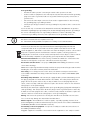
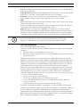
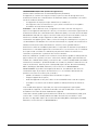
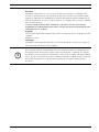
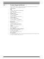
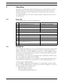
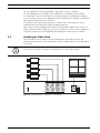
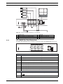
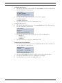
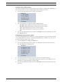
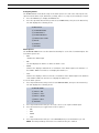
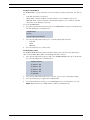
Digital Video Quad Processor LTC 2380/90, LTC 2382/90 en User Manuall Digital Video Quad Processor Table of Contents | en iii Table of Contents 1 Safety 1 1.1 Important Safety Instructions 1 1.2 Safety Precautions 3 1.3 Important Notices 3 1.4 Customer Support and Service 8 2 Unpacking 9 2.1 Parts List 9 2.2 Description 9 2.3 Installing the Video Quad 10 2.3.1 LTC 2380/90 Rear Panel Connections 11 2.3.2 LTC 2382/90 Rear Panel Connections 12 2.3.3 Wiring Requirements 12 2.3.4 Grounding Connection 14 2.3.5 Installing the Video Quad in a 19-inch Rack 14 2.4 Programming the LTC 2382/90 Video Processor 18 2.4.1 LTC 2382/90 Front Panel Function Keys 18 2.4.2 Using the Function Keys (LTC 2382/90) 19 2.5 Operating the Video Quad Processors 30 2.5.1 Operating the LTC 2382/90 Video Quad Processor 30 2.5.2 Controlling the Video Quad Processor Remotely 34 2.5.3 Restoring Factory Default Settings 38 2.6 Maintenance 38 2.7 Technical Specifications 39 3 Index 41 Bosch Security Systems, Inc. User Manual F.01U.090.110 | 3.0 | 2010.04 iv en | Table of Contents F.01U.090.110 | 3.0 | 2010.04 Digital Video Quad Processor User Manual Bosch Security Systems, Inc. Digital Video Quad Processor Safety | en 1 Safety 1.1 Important Safety Instructions 1 Read, follow, and retain for future reference all of the following safety instructions. Heed all warnings on the unit and in the operating instructions before operating the unit. 1. Cleaning - Unplug the unit from the outlet before cleaning. Follow any instructions provided with the unit. Generally, using a dry cloth for cleaning is sufficient, but a moist fluff-free cloth or leather shammy may also be used. Do not use liquid cleaners or aerosol cleaners. 2. Heat Sources - Do not install the unit near any heat sources such as radiators, heaters, stoves, or other equipment (including amplifiers) that produce heat. 3. Ventilation - Any openings in the unit enclosure are provided for ventilation to prevent overheating and ensure reliable operation. Do not block or cover these openings. Do not place the unit in an enclosure unless proper ventilation is provided, or the manufacturer's instructions have been adhered to. 4. Water - Do not use this unit near water, for example near a bathtub, washbowl, sink, laundry basket, in a damp or wet basement, near a swimming pool, in an outdoor installation, or in any area classified as a wet location. To reduce the risk of fire or electrical shock, do not expose this unit to rain or moisture. 5. Object and liquid entry - Never push objects of any kind into this unit through openings as they may touch dangerous voltage points or short-out parts that could result in a fire or electrical shock. Never spill liquid of any kind on the unit. Do not place objects filled with liquids, such as vases or cups, on the unit. 6. Lightning - For added protection during a lightning storm, or when leaving this unit unattended and unused for long periods, unplug the unit from the wall outlet and disconnect the cable system. This will prevent damage to the unit from lightning and power line surges. 7. Controls adjustment - Adjust only those controls specified in the operating instructions. Improper adjustment of other controls may cause damage to the unit. Use of controls or adjustments, or performance of procedures other than those specified, may result in hazardous radiation exposure. 8. Overloading - Do not overload outlets and extension cords. This can cause fire or electrical shock. 9. Power cord and plug protection - Protect the plug and power cord from foot traffic, being pinched by items placed upon or against them at electrical outlets, and its exit from the unit. For units intended to operate with 230 VAC, 50 Hz, the input and output power cord must comply with the latest versions of IEC Publication 227 or IEC Publication 245. 10. Power disconnect - Units with or without ON/OFF switches have power supplied to the unit whenever the power cord is inserted into the power source; however, the unit is operational only when the ON/OFF switch is in the ON position. The power cord is the main power disconnect device for switching off the voltage for all units. Bosch Security Systems, Inc. User’s Guide F.01U.090.110 | 3.0 | 2010.04 2 en | Safety Digital Video Quad Processor 11. Power sources - Operate the unit only from the type of power source indicated on the label. Before proceeding, be sure to disconnect the power from the cable to be installed into the unit. – For battery powered units, refer to the operating instructions. – For external power supplied units, use only the recommended or approved power supplies. – For limited power source units, this power source must comply with EN60950. Substitutions may damage the unit or cause fire or shock. – For 24 VAC units, voltage applied to the unit's power input should not exceed ±10%, or 28 VAC. User-supplied wiring must comply with local electrical codes (Class 2 power levels). Do not ground the supply at the terminals or at the unit's power supply terminals. – If unsure of the type of power supply to use, contact your dealer or local power company. 12. Servicing - Do not attempt to service this unit yourself. Opening or removing covers may expose you to dangerous voltage or other hazards. Refer all servicing to qualified service personnel. 13. Damage requiring service - Unplug the unit from the main AC power source and refer servicing to qualified service personnel when any damage to the equipment has occurred, such as: – the power supply cord or plug is damaged; – exposure to moisture, water, and/or inclement weather (rain, snow, etc.); – liquid has been spilled in or on the equipment; – an object has fallen into the unit; – unit has been dropped or the unit cabinet is damaged; – unit exhibits a distinct change in performance; – unit does not operate normally when the user correctly follows the operating instructions. 14. Replacement parts - Be sure the service technician uses replacement parts specified by the manufacturer, or that have the same characteristics as the original parts. Unauthorized substitutions may cause fire, electrical shock, or other hazards. 15. Safety check - Safety checks should be performed upon completion of service or repairs to the unit to ensure proper operating condition. 16. Installation - Install in accordance with the manufacturer's instructions and in accordance with applicable local codes. 17. Attachments, changes or modifications - Only use attachments/accessories specified by the manufacturer. Any change or modification of the equipment, not expressly approved by Bosch, could void the warranty or, in the case of an authorization agreement, authority to operate the equipment. F.01U.090.110 | 3.0 | 2010.04 User’s Guide Bosch Security Systems, Inc. Digital Video Quad Processor 1.2 Safety | en 3 Safety Precautions DANGER! High risk: This symbol indicates an imminently hazardous situation such as “Dangerous Voltage” inside the product. If not avoided, this will result in an electrical shock, serious bodily injury, or death. ! WARNING! Medium risk: Indicates a potentially hazardous situation. If not avoided, this could result in serious bodily injury or death. WARNING! Indicates a potentially hazardous situation. If not avoided, this may result in minor or moderate injury. Alerts the user to important instructions accompanying the unit. ! i 1.3 WARNING! Low risk: (without safety alert symbol) Indicates a potentially hazardous situation. If not avoided, this may result in property damage or risk of damage to the unit. NOTICE! This symbol indicates information or a company policy that relates directly or indirectly to the safety of personnel or protection of property. Important Notices Accessories - Do not place this unit on an unstable stand, tripod, bracket, or mount. The unit may fall, causing serious injury and/or serious damage to the unit. Use only with the cart, stand, tripod, bracket, or table specified by the manufacturer. When a cart is used, use caution and care when moving the cart/apparatus combination to avoid injury from tip-over. Quick stops, excessive force, or uneven surfaces may cause the cart/unit combination to overturn. Mount the unit per the manufacturer's instructions. All-pole power switch - Incorporate an all-pole power switch, with a contact separation of at least 3 mm in each pole, into the electrical installation of the building. If it is needed to open the housing for servicing and/or other activities, use this all-pole switch as the main disconnect device for switching off the voltage to the unit. Camera grounding - For mounting the camera in potentially damp environments, ensure to ground the system using the ground connection of the power supply connector (see section: Connecting external power supply). Camera lens - An assembled camera lens in the outdoor housing must comply and be tested in accordance with UL/IEC60950. Any output or signal lines from the camera must be SELV or Limited Power Source. For safety reasons the environmental specification of the camera lens assembly must be within the environmental specification of -10 °C (14 °F) to 50 °C (122 °F). Camera signal - Protect the cable with a primary protector if the camera signal is beyond 140 feet, in accordance with NEC800 (CEC Section 60). Bosch Security Systems, Inc. User’s Guide F.01U.090.110 | 3.0 | 2010.04 4 en | Safety Digital Video Quad Processor Coax grounding: – – Ground the cable system if connecting an outside cable system to the unit. Connect outdoor equipment to the unit's inputs only after this unit has had its grounding plug connected to a grounded outlet or its ground terminal is properly connected to a ground source. – Disconnect the unit's input connectors from outdoor equipment before disconnecting the grounding plug or grounding terminal. – Follow proper safety precautions such as grounding for any outdoor device connected to this unit. U.S.A. models only - Section 810 of the National Electrical Code, ANSI/NFPA No.70, provides information regarding proper grounding of the mount and supporting structure, grounding of the coax to a discharge unit, size of grounding conductors, location of discharge unit, connection to grounding electrodes, and requirements for the grounding electrode. i NOTICE! This device is intended for use in public areas only. U.S. federal law strictly prohibits surreptitious recording of oral communications. Your Bosch product was developed and manufactured with high-quality material and components that can be recycled and reused. This symbol means that electronic and electrical appliances, which have reached the end of their working life, must be collected and disposed of separately from household waste material. Separate collecting systems are usually in place for disused electronic and electrical products. Please dispose of these units at an environmentally compatible recycling facility, per European Directive 2002/96/EC. Environmental statement - Bosch has a strong commitment towards the environment. This unit has been designed to respect the environment as much as possible. Electrostatic-sensitive device - Use proper CMOS/MOS-FET handling precautions to avoid electrostatic discharge. NOTE: Wear required grounded wrist straps and observe proper ESD safety precautions when handling the electrostatic-sensitive printed circuit boards. Fuse rating - For security protection of the device, the branch circuit protection must be secured with a maximum fuse rating of 16A. This must be in accordance with NEC800 (CEC Section 60). Grounding and polarization - This unit may be equipped with a polarized alternating current line plug (a plug with one blade wider than the other blade). This safety feature allows the plug to fit into the power outlet in only one way. If unable to insert the plug fully into the outlet, contact a locally certified electrician to replace the obsolete outlet. Do not defeat the safety purpose of the polarized plug. Alternately, this unit may be equipped with a 3-pole grounding plug (a plug with a third pin for earth grounding). This safety feature allows the plug to fit into a grounded power outlet only. If unable to insert the plug into the outlet, contact a locally certified electrician to replace the obsolete outlet. Do not defeat the safety purpose of the grounding plug. Moving - Disconnect the power before moving the unit. Move the unit with care. Excessive force or shock may damage the unit and the hard disk drives. Outdoor signals - The installation for outdoor signals, especially regarding clearance from power and lightning conductors and transient protection, must be in accordance with NEC725 and NEC800 (CEC Rule 16-224 and CEC Section 60). Permanently connected equipment - Incorporate a readily accessible disconnect device in the building installation wiring. Pluggable equipment - Install the socket outlet near the equipment so it is easily accessible. F.01U.090.110 | 3.0 | 2010.04 User’s Guide Bosch Security Systems, Inc. Digital Video Quad Processor Safety | en 5 PoE - Never supply power via the Ethernet connection (PoE) when power is already supplied via the power connector. Power disconnect - Units have power supplied whenever the power cord is inserted into the power source. The power cord is the main power disconnect for all units. Power lines - Do not locate the camera near overhead power lines, power circuits, or electrical lights, nor where it may contact such power lines, circuits, or lights. SELV All the input/output ports are Safety Extra Low Voltage (SELV) circuits. SELV circuits should only be connected to other SELV circuits. Because the ISDN circuits are treated like telephone-network voltage, avoid connecting the SELV circuit to the Telephone Network Voltage (TNV) circuits. Video loss - Video loss is inherent to digital video recording; therefore, Bosch Security Systems cannot be held liable for any damage that results from missing video information. To minimize the risk of lost digital information, Bosch Security Systems recommends multiple, redundant recording systems, and a procedure to back up all analog and digital information. i NOTICE! This is a class A product. In a domestic environment this product may cause radio interference, in which case the user may be required to take adequate measures. FCC & ICES INFORMATION (U.S.A. and Canadian Models Only, CLASS B) This device complies with part 15 of the FCC Rules. Operation is subject to the following two conditions: 1. 2. This device may not cause harmful interference, and This device must accept any interference received, including interference that may cause undesired operation. NOTE: This equipment has been tested and found to comply with the limits for a Class B digital device, pursuant to Part 15 of the FCC Rules and ICES-003 of Industry Canada. These limits are designed to provide reasonable protection against harmful interference when the equipment is operated in a residential installation. This equipment generates, uses and can radiate radio frequency energy, and if not installed and used in accordance with the instructions, may cause harmful interference to radio communications. However, there is no guarantee that interference will not occur in a particular installation. If this equipment does cause harmful interference to radio or television reception, which can be determined by turning the equipment off and on, the user is encouraged to try to correct the interference by one or more of the following measures: – Reorient or relocate the receiving antenna. – Increase the separation between the equipment and receiver. – Connect the equipment into an outlet on a circuit different from that to which the receiver is connected. – Consult the dealer, or an experienced radio/TV technician for help. Intentional or unintentional changes or modifications, not expressly approved by the party responsible for compliance, shall not be made. Any such changes or modifications could void the user’s authority to operate the equipment.The user may find the following booklet, prepared by the Federal Communications Commission, helpful: How to Identify and Resolve Radio-TV Interference Problems. This booklet is available from the U.S. Government Printing Office, Washington, DC 20402, Stock No. 004-000-00345-4. Bosch Security Systems, Inc. User’s Guide F.01U.090.110 | 3.0 | 2010.04 6 en | Safety Digital Video Quad Processor INFORMATIONS FCC ET ICES (Residential applications) (modèles utilisés aux États-Unis et au Canada uniquement, CLASSE B) Cet appareil est conforme aux exigences imposées par la section 15 du règlement de la Commission fédérale des communications des États-Unis (FCC). Son utilisation est soumise aux deux conditions suivantes: – Cet appareil ne doit pas provoquer d'interférences nuisibles, et – doit supporter toutes les interférences reçues, dont les interférences susceptibles d'entraîner un fonctionnement imprévu. REMARQUE : suite à différents tests, cet appareil s'est révélé conforme aux exigences imposées aux appareils numériques de classe B, en vertu de la section 15 du règlement de la Commission fédérale des communications des États-Unis (FCC), et en vertu de la norme ICES003 d'Industrie Canada. Ces exigences visent à fournir une protection raisonnable contre les interférences nuisibles lorsque l'appareil est utilisé dans le cadre d'une installation résidentielle. Cet appareil génère, utilise et émet de l'énergie de radiofréquences et peut, en cas d'installation ou d'utilisation non conforme aux instructions, engendrer des interférences nuisibles au niveau des radiocommunications. Toutefois, rien ne garantit l'absence d'interférences dans une installation particulière. Il est possible de déterminer la production d'interférences en mettant l'appareil successivement hors et sous tension, tout en contrôlant la réception radio ou télévision. L'utilisateur peut parvenir à éliminer les interférences éventuelles en prenant une ou plusieurs des mesures suivantes: Au besoin, l’utilisateur consultera son revendeur ou un technicien qualifié en radio/télévision, qui procédera à une opération corrective. La brochure suivante, publiée par la Commission fédérale des communications (FCC), peut s’avérer utile : « How to Identify and Resolve RadioTV Interference Problems » (Comment identifier et résoudre les problèmes d’interférences de radio et de télévision). Cette brochure est disponible auprès du U.S. Government Printing Office, Washington, DC 20402, États-Unis, sous la référence n° 004-000-00345-4. AVERTISSEMENT: Ce produit est un appareil de Classe A. Son utilisation dans une zone résidentielle risque de provoquer des interférences. Le cas échéant, l’utilisateur devra prendre les mesures nécessaires pour y remédier. – Modifier l'orientation ou l'emplacement de l'antenne réceptrice; – Éloigner l'appareil du récepteur; – Brancher l'appareil sur une prise située sur un circuit différent de celui du récepteur; – Consulter le revendeur ou un technicien qualifié en radio/télévision pour obtenir de l'aide. Toute modification apportée au produit, non expressément approuvée par la partie responsable de l'appareil, est strictement interdite. Une telle modification est susceptible d'entraîner la révocation du droit d'utilisation de l'appareil. La brochure suivante, publiée par la Commission fédérale des communications (FCC), peut s'avérer utile : « How to Identify and Resolve Radio-TV Interference Problems ». Cette brochure est disponible auprès du U.S. Government Printing Office, Washington, DC 20402, États-Unis, sous la référence n° 004-000-00345-4. F.01U.090.110 | 3.0 | 2010.04 User’s Guide Bosch Security Systems, Inc. Digital Video Quad Processor Safety | en 7 Disclaimer Underwriter Laboratories Inc. (“UL”) has not tested the performance or reliability of the security or signaling aspects of this product. UL has only tested fire, shock and/or casualty hazards as outlined in UL's Standard(s) for Safety for Closed Circuit Television Equipment, UL 2044. UL Certification does not cover the performance or reliability of the security or signaling aspects of this product. UL MAKES NO REPRESENTATIONS, WARRANTIES, OR CERTIFICATIONS WHATSOEVER REGARDING THE PERFORMANCE OR RELIABILITY OF ANY SECURITY OR SIGNALING RELATED FUNCTIONS OF THIS PRODUCT. Copyright This user guide is the intellectual property of Bosch Security Systems, Inc. and is protected by copyright. All rights reserved. Trademarks All hardware and software product names used in this document are likely to be registered trademarks and must be treated accordingly. NOTICE! This user guide has been compiled with great care and the information it contains has been i thoroughly verified. The text was complete and correct at the time of printing. The ongoing development of the products may mean that the content of the user guide can change without notice. Bosch Security Systems accepts no liability for damage resulting directly or indirectly from faults, incompleteness or discrepancies between the user guide and the product described. Bosch Security Systems, Inc. User’s Guide F.01U.090.110 | 3.0 | 2010.04 8 1.4 en | Safety Digital Video Quad Processor Customer Support and Service If this unit needs service, contact the nearest Bosch Security Systems Service Center for authorization to return and shipping instructions. Service Centers USA Telephone: 800-366-2283 or 585-340-4162 Fax: 800-366-1329 Email: cctv.repair@us.bosch.com Customer Service Telephone: 888-289-0096 Fax: 585-223-9180 Email: security.sales@us.bosch.com Technical Support Telephone: 800-326-1450 Fax: 585-223-3508 or 717-735-6560 Email: technical.support@us.bosch.com Repair Center Telephone: 585-421-4220 Fax: 585-223-9180 or 717-735-6561 Email: security.repair@us.bosch.com Canada Telephone: 514-738-2434 Fax: 514-738-8480 Europe, Middle East & Asia Pacific Region Telephone: 44 (0) 1495 274558 Fax: 44 (0) 1495 274280 Email: rmahelpdesk@solectron.com More information For additional information, please contact your Bosch Security Systems representative or visit our web site at www.boschsecurity.com F.01U.090.110 | 3.0 | 2010.04 User’s Guide Bosch Security Systems, Inc. Digital Video Quad Processor 2 Unpacking | en 9 Unpacking This equipment should be unpacked and handled with care. If an item appears to have been damaged in shipment, notify the shipper. Verify that all parts shown in the Parts List are included. If any items are missing, notify your Bosch Security Systems Sales or Customer Service Representative. The original packing carton is the safest container in which to transport the unit. Save it for possible future use. 2.1 Parts List The LTC238x/90 package contains the following items. Qty. Equipment Part Number 1 Video Quad Digital Video Processor LTC 2380/90 or LTC 2382/90 1 External power supply GQ-PSU-00 1 US mains lead CBL-IEC-US 1 European mains lead CBL-IEC-EU 1 UK mains lead CBL-IEC-IRL 1 19-inch rack mounting kit for single or 'side by side' rack mounting, which includes: 1 – 1 binding plate GQ-M-BKT-02-00 – 1 short mounting ear GQ-M-BKT-00-00 – 1 long mounting ear GQ-M-BKT-01-00 – 4 M3 x 6 mm cheese-head Phillips screws F-PCHS-M3x6 15 way D-type break-out connection board GQ-ASY-AD-00 (LTC 2382/90 model only) 1 2.2 This manual F01U029247 Description The LTC 238x/90 Video Quad Processors use the latest integrated technology to produce high quality, real time video in both Full and Quad Screen modes. The display is updated at the field rate of 60 fields per second for EIA/NTSC or 50 fields per second for CCIR/PAL, providing real time video. The Video Quad processors require no external synchronization and accept video inputs with 2:1 interlaced source. The Video Quad processors auto detect the applicable video standard, PAL or NTSC, camera type, color or B/W, and configures itself accordingly. The LTC 2380/90 Video Quad processor is designed for easy installation in applications where four cameras need to be viewed on a single monitor. It offers a quad display with no user controls required - truly plug and play. The LTC 2382/90 is a full-featured Video Quad processor; which includes a monitor output plus a second output (REC OUT) that sends video to an external recording device. You can set the monitor output for these display options: – Quad display (all four cameras). – Full-screen display (any camera). – Sequencing with programmable dwell time. Bosch Security Systems, Inc. User’s Guide F.01U.090.110 | 3.0 | 2010.04 10 en | Unpacking Digital Video Quad Processor The LTC 2382/90 also offers programmable camera titles of up to 8 characters. The LTC 2382/90 allows recording in Full or Quad modes of individual cameras. Quad recorded images can be viewed in full screen using the built-in zoom playback. In addition, you can remotely control the LTC 2382/90, as well as synchronize the unit with external time/ date signals through an RS-232 connection. Several units may be daisy chained together so that all can be controlled from one PC. Individual units are identified by setting the UNIT ID parameter. Other features include a flashing alarm indicator, programmable audible alarm, a video loss output relay and an alarm output relay for control of a VCR or other device. Also available are front panel alarm clear, user programmable alarm dwell time, and a video loss indicator. 2.3 Installing the Video Quad These units allow user-friendly on-screen programming for quick-and-easy setup. The following figures illustrate connecting cameras, monitors, alarms and video recording devices to the units. i NOTICE! It may be necessary to connect a separate ground connection to the grounding screw on the rear panel to eliminate electrical interference on the video images. IN 1 2 3 4 MON 2 1 GND Figure 2.1 F.01U.090.110 | 3.0 | 2010.04 3 5V DC 4 OUT Typical Installation Configuration for LTC 2380/90 User’s Guide Bosch Security Systems, Inc. Digital Video Quad Processor Unpacking | en PLAY IN IN GND 1 4 3 2 1 ALM/RS-232 3 2 1 1 2 3 2.3.1 MON 5V DC 4 OUT REC OUT 2 3 4 5 6 Figure 2.2 11 Typical Installation Configuration for LTC 2382/90 RS232 to PC Alarm In (pins 1 to 5, typical alarm) Auto Terminating Video Loop Outputs 4 5 6 PLAY IN REC OUT (record out) VCR or DVR LTC 2380/90 Rear Panel Connections The figure below illustrates the rear panel connectors for the LTC 2380/90 video processor. IN 1 2 3 4 MON 1 GND Figure 2.3 2 3 5V DC 4 OUT LTC 2380/90 Rear Panel Video Inputs/Outputs IN 1 Video Input 1 - BNC 75 Ohm, auto terminating IN 2 Video Input 2 - BNC 75 Ohm, auto terminating IN 3 Video Input 3 - BNC 75 Ohm, auto terminating IN 4 Video Input 4 - BNC 75 Ohm, auto terminating OUT 1 Video Loop Output 1 - BNC OUT 2 Video Loop Output 2 - BNC OUT 3 Video Loop Output 3 - BNC OUT 4 Video Loop Output 4 - BNC MON Monitor Output Video - BNC 75 Ohm output impedance Power 5V DC 2.0 mm DC Power Jack (outside diameter: 6.4 mm, pin diameter: 2.0 mm GND Screw to connect an external earth wire Bosch Security Systems, Inc. User’s Guide F.01U.090.110 | 3.0 | 2010.04 12 en | Unpacking 2.3.2 Digital Video Quad Processor LTC 2382/90 Rear Panel Connections The figure below illustrates the rear panel connectors for the LTC 2382/90 video processor. IN VCR IN 2 1 GND 3 4 ALARM/REMOTE OUT Figure 2.4 VCR OUT MON 5V DC LTC 2382/90 Rear Panel Video Inputs/Outputs IN 1 Video Input 1 - BNC 75 Ohm, auto terminating IN 2 Video Input 2 - BNC 75 Ohm, auto terminating IN 3 Video Input 3 - BNC 75 Ohm, auto terminating IN 4 Video Input 4 - BNC 75 Ohm, auto terminating OUT 1 Video Loop Output 1 - BNC OUT 2 Video Loop Output 2 - BNC OUT 3 Video Loop Output 3 - BNC OUT 4 Video Loop Output 4 - BNC PLAY IN VCR/DVR Video Input - BNC 75 Ohm input impedance REC OUT Video Output to VCR/DVR - BNC 75 Ohm output impedance MON Monitor Output Video - BNC 75 Ohm output impedance Power 2.3.3 5V DC 2.0 mm DC Power Jack (outside diameter: 6.4 mm, pin diameter: 2.0 mm) GND Screw to connect an external earth wire Wiring Requirements Use the table below to determine the appropriate wires for terminals, alarms, trigger output, and an RS-232 connector. Application Recommended Wire Type Terminals 16–30 AWG or 0.5 mm–1 mm, shielded cable Alarm Inputs 20 AWG stranded, shielded cable Thresholds– High: 2.4 to 5.0 VDC; Low: 0.0 to 0.8 VDC Trigger Output 20 AWG stranded, shielded cable Maximum voltage: 30 VDC Recommended pull-up voltage: 5 VDC Recommended pull-up resistor value for 5 V: 5 K–10 K RS-232 20 AWG stranded, shielded cable Maximum distance: 15.4 m (50 ft) F.01U.090.110 | 3.0 | 2010.04 User’s Guide Bosch Security Systems, Inc. Digital Video Quad Processor Unpacking | en 13 Alarm/RS-232 Connector The following figure illustrates the positions of the inputs in the 15 way D-type break-out connection board. This board connect to the 15 Pin D-type connector, located on the rear panel of the LTC 2382/90 Video Quad processor. S 15 14 13 12 11 10 9 Figure 2.5 1 2 3 4 5 6 7 8 +VDC external 15-pin D-type Pinout ALARM/REMOTE (15 Pin D-Type) Pin 1 Alarm Input 1 Pin 2 Alarm Input 2 Pin 3 Alarm Input 3 Pin 4 Alarm Input 4 Pin 5 Ground Pin 6 Trigger Output (Open Collector Alarm Output) Pin 7 Ground Pin 8 TXD RS-232 Transmit Data Pin 9 RXD RS-232 Receive Data Pin 10 Alarm Relay NC (Alarm Relay Contact Normally Closed) Pin 11 Alarm Relay COM (Alarm Relay Contact Common) Pin 12 Alarm Relay NO (Alarm Relay Contact Normally Open) Pin 13 Video Loss Relay NC (Video Loss Relay Contact Normally Closed) Pin 14 Video Loss Relay COM (Video Loss Relay Contact Common) Pin 15 Video Loss Relay NO (Video Loss Relay Contact Normally Open) Bosch Security Systems, Inc. User’s Guide F.01U.090.110 | 3.0 | 2010.04 14 en | Unpacking Digital Video Quad Processor The following illustration depicts a typical Normally Open alarm circuit, where Pin 1 accepts the alarm input and Pin 5 is the ground: S 15 14 13 12 11 10 9 Figure 2.6 2.3.4 1 2 3 4 5 6 7 8 Typical Normally Open Alarm Circuit Diagram Grounding Connection It may be necessary to connect a separate ground connection to the grounding screw on the rear panel to eliminate electrical interference on the video images. 2.3.5 Installing the Video Quad in a 19-inch Rack There are two options for installing the unit in a 19-inch rack. A single unit can be installed in a rack using the long and the short mounting ears and screws supplied with the unit. Two units can be installed side by side in a rack using the binding plates (one plate supplied with each unit) and the two (2) short mounting ears (one short ear provided with each unit). Installing a Single Unit 1. Remove the rubber feet from the bottom of the unit. These feet may interfere with installing other hardware in the rack mount. 2. Remove the two (2) screws from the front side (A) of each unit. 2 A Figure 2.7 3. Side-view of Video Quad Unit Attach the short rack ear to the right side of the unit using two (2) M3 x 6 mm cheesehead screws (included with the rack mount kit). 4. Attach the long rack ear to the left of the unit using two (2) M3 x 6 mm cheese-head screws (included with the rack mount kit). MODE PLAY 4 MENU DISPLAY SEQ 1 2 3 4 3 ALM Figure 2.8 5. F.01U.090.110 | 3.0 | 2010.04 Short Ear (right) and Long Ear (left) Attached to the Unit Use four (4) bolts (not included) to attach the short and long rack ears to the rack mount. User’s Guide Bosch Security Systems, Inc. Digital Video Quad Processor Unpacking | en 15 Installing a Double Unit The package for each Video Quad contains a binding plate that you use to connect two units together. To connect two units you must connect one (1) binding plate to the bottoms of the units and one (1) binding plate to the tops of the units. The connected units fit into a 19-inch rack unit. 1. Turn the units over so that the front panels are towards you. 2. Remove the rubber feet from the bottom of both units. These feet may interfere with installing other hardware in the rack mount. 3. Determine which unit will server as the right-side unit and which as the left-side unit. 4. Remove the left, front screw (A) from the bottom of the right unit (B). B A Figure 2.9 Position of Screw to Remove from the Right Unit 5. Remove the right, front screw (C) from the bottom of the left unit (D). D C Figure 2.10 Bosch Security Systems, Inc. Position of Screw to Remove from the Left Unit User’s Guide F.01U.090.110 | 3.0 | 2010.04 16 en | Unpacking Digital Video Quad Processor 6. Connect both units (B and D) by attaching one (1) binding plate to the bottom of each unit (E and F). Use the two (2) screws removed from the bottom of the units and two (2) additional screws included with the rack mount kit. (Note that the illustrations shows a gap between the two units for clarity, in actuality, there should not be a gap between the units.) F E B D F Figure 2.11 E Binding Plate Connected to the Bottoms of Both Units 7. Turn the connected units over and ensure that the front panel is towards you. 8. Remove the front and back inner screws from the tops of both units (G and H). Retain these four (4) screws. H G B D H Figure 2.12 F.01U.090.110 | 3.0 | 2010.04 C G Top View of Connected Units User’s Guide Bosch Security Systems, Inc. Digital Video Quad Processor 9. Unpacking | en 17 Connect both units by attaching the second binding plate to the top of each unit (I and J). Use the four (4) screws removed from tops of the units. J I B D J Figure 2.13 C I Binding Plate Connected to the Tops of Both Units 10. Remove the two (2) screws (K) from the outside front edge (A) of each double unit. K A Figure 2.14 Side-view of Video Quad Unit 11. Attach a short rack ear to the left, outside edge of the double unit using two (2) M3 x 6 mm cheese-head screws (included with the rack mount kit). 12. Attach the second short rack ear to the right, outside edge of the double-unit using two (2) M3 x 6 mm cheese-head screws (included with the rack mount kit). 13. Use four (4) bolts (not included) to attach the short rack ears (L and M) to the rack mount. MODE M PLAY MENU DISPLAY SEQ 1 2 3 MODE 4 ALM Figure 2.15 Bosch Security Systems, Inc. PLAY MENU DISPLAY SEQ 1 2 3 4 L ALM Short Ears Attached to the Double Unit User’s Guide F.01U.090.110 | 3.0 | 2010.04 18 en | Unpacking 2.4 Digital Video Quad Processor Programming the LTC 2382/90 Video Processor The main difference between the LTC 2380/90 and the LTC 2382/90 video processors is the ability to program the LTC 2382/90 via the front panel controls. The following figures illustrate the front panels for both video processors. 2.4.1 Figure 2.16 LTC 2380/90 Front Panel Figure 2.17 LTC 2382/90 Front Panel LTC 2382/90 Front Panel Function Keys All programming is done with the front panel keys. There are eight keys on the front panel. Key Label Operating Function Programming Function PLAY Selects PLAY input for display NONE on monitor MENU SEQ ALM Selects the on-screen menu Enters the programming mode Selects the sequential NONE switching function and Alarm Acknowledge 1 ^ 2 3 4 Quad Table 2.1 F.01U.090.110 | 3.0 | 2010.04 < > Return Displays Camera 1 in Full- Scrolls up through program selections: screen mode selects entries Displays Camera 2 in Full- Scrolls down through program screen mode selections: selects entries Displays Camera 3 in Full- Moves cursor to the left in menus; selects screen mode entries Displays Camera 4 in Full- Moves cursor to the right in menus; screen mode selects entries Displays Quad mode Return (Enter) or set function LTC 2382/90 Front Panel Function Keys User’s Guide Bosch Security Systems, Inc. Digital Video Quad Processor 2.4.2 Unpacking | en 19 Using the Function Keys (LTC 2382/90) Programming the LTC 2382/90 includes setting titles for the video inputs, assigning dwell times for each video input and quad display for sequencing (SEQ) operation, enabling or disabling the alarms, and video loss alarm and enabling or disabling the security lock. Each of these functions are pre-programmed with a factory default setting. If there is no key activity while in Menu mode for one minute the unit automatically exits the menu mode. To access the MAIN menu: 1. Press the MENU key to display the MAIN menu screen. The unit displays the following screen: MAIN MENU VER X.X (1) TIME/DATE (2) SEQ SETUP (3) ALARM SETUP (4) REC OUT MODE (5) CAMERA TITLES (6) COLOR ADJUST (7) SYSTEM SETTINGS > (8) EXIT MENU The PLAY and SEQ/ALM keys are not used in programming. See Table 2.1 above for descriptions of the function keys. i NOTICE! The Video Quad illuminates the appropriate LEDs, located on the front panel, for active keys. Configuring the Time and Date Set the time and date format, the current time/date and the displayed position on the monitor from the TIME/DATE menu. 1. 2. Access the MAIN menu. Press the Up and Down arrow keys and select TIME/DATE; then press the Return key. The unit displays the following menu: TIME/DATE (1) TIME FORMAT (2) DATE FORMAT (3) TIME/DATE SET (4) DISPLAY: TOP 1 > Bosch Security Systems, Inc. (5) RETURN User’s Guide F.01U.090.110 | 3.0 | 2010.04 20 en | Unpacking Digital Video Quad Processor Setting the Time Format 1. Press the Up and Down arrow keys and select TIME FORMAT; then press the Return key. The unit displays the following menu: TIME FORMAT 12 HOURS (AM/PM) TO EXIT PRESS RETURN KEY 2. Press the Up and Down arrow keys and select from these options: 12 HOURS (AM/PM) 24 HOURS (00:00-23:59) 3. Press the Return key to return to the TIME/DATE menu. Setting the Date Format 1. Press the Up and Down arrow keys to select DATE FORMAT; then press the Return key. The unit displays the following menu: DATE FORMAT MM/DD/YY TO EXIT PRESS RETURN KEY 2. 3. Press the Up and Down arrow keys and select one of the following options: – MM/DD/YY – DD/MM/YY – YY/MM/DD Press the Return key to return to the TIME/DATE menu. Setting the Current Time and Date 1. Press the up and down arrow keys and select TIME/DATE SET; then press the Return key. The unit displays the following menu: TIME/DATE SET 24 HOUR MM/DD/YY 11:00:00 AM 01/31/2006 TO EXIT PRESS RETURN KEY 2. Press the Left and Right arrow keys to move the cursor to the required position. 3. Press the Up and Down arrow keys to establish the correct digit. 4. Press the Return key to return to the TIME/DATE menu. F.01U.090.110 | 3.0 | 2010.04 User’s Guide Bosch Security Systems, Inc. Digital Video Quad Processor Unpacking | en 21 Setting the Time and Date Display The monitor displays the date and time and the video from the recording device (REC OUT) in the selected position. The new setting is applied when exiting menu mode. 1. Press the Up and Down arrow keys and select DISPLAY. TIME/DATE (1) TIME FORMAT (2) DATE FORMAT (3) TIME/DATE SET > (4) DISPLAY:TOP 1 (5) RETURN 2. 3. Press the Return key to toggle through the display options: – BOTTOM 1 (approximately 5% from the bottom of the monitor) – BOTTOM 2 (approximately 10% from the bottom of the monitor) – TOP 1 (approximately 5% from the top of the monitor) – TOP 2 (approximately 10% from the top of the monitor) – OFF Press the Up and Down arrow keys and select RETURN; then press the Return key to exit the TIME/DATE menu. Configuring the Camera Sequence Setup You use the SEQ SETUP menu to adjust the sequence dwell times of the four cameras in Full screen and the Quad screen mode. You may program dwell times as SKIP or as 2, 3, 4, 5, 6, 7, 8, 9, 10, 20, 30, 50, 60, 80, or 99 seconds. 1. 2. Press the MENU key to display the MAIN menu. Press the Up and Down arrow keys and select SEQ SETUP; then press the Return key. The unit displays the following menu: SEQ SETUP (1) CAMERA 1: 9 SEC (2) CAMERA 2: 9 SEC (3) CAMERA 3: 9 SEC > (4) CAMERA 4: SKIP (5) QUAD: 9 SEC (6) RETURN 3. 4. Press Up and Down arrow keys to move the cursor to the required camera. Press the Return key to scroll through the dwell times. When you reach SKIP, press the Return key to toggle through the sequence again. 5. Press the Up and Down arrow key and select RETURN; then press the Return key to exit the menu. Bosch Security Systems, Inc. User’s Guide F.01U.090.110 | 3.0 | 2010.04 22 en | Unpacking Digital Video Quad Processor Configuring Alarms The ALARM SETUP menu allows setup of the alarm options for each of the video inputs. The options include alarm on/off, dwell time, polarity, video loss, relay on/off, and beeper on/off. 1. Press the MENU key to display the MAIN menu. 2. Press the up and down arrow keys and select ALARM SETUP; then press the Return key. The unit displays the following menu: ALARM SETUP (1) ALARM OPTIONS (2) ALARM DWELL (3) ALARM POLARITY (4) VIDEO LOSS ALERT (5) RELAY (6) BEEPER > (7) RETURN Alarm Options The ALARM OPTIONS menu sets the alarm functionality for each of the four Alarm inputs. The four alarms options are: – OFF disables the Alarm Input. – ON the unit displays the alarm icon when an alarm occurs. – QUAD switches the display to Quad mode on activation of the Alarm Input for the duration. of the DWELL TIME. The unit does not display the Alarm icon. – FULL switches the display to Full-screen mode on activation of the Alarm Input for the duration of the DWELL TIME. The unit does not display the Alarm icon. To set the alarm options: 1. Press Up and Down arrow keys and select ALARM OPTIONS; then press the Return key. The unit displays the following menu: ALARM OPTIONS (1) INPUT 1: ON (2) INPUT 2: FULL (3) INPUT 3: QUAD (4) INPUT 4: OFF > 2. 3. 4. (5) RETURN Press Up and Down arrow keys to move the cursor to the required alarm input. Press the Return key to toggle between these options: – ON – OFF – QUAD – FULL Press Up and Down arrow keys to select RETURN; then press the Return key to exit. NOTE: The Relay and Beeper functions are activated if they are enabled. F.01U.090.110 | 3.0 | 2010.04 User’s Guide Bosch Security Systems, Inc. Digital Video Quad Processor Unpacking | en 23 Setting the Alarm Dwell The ALARM DWELL sets the automatic reset period after an alarm is generated. The options are: – 1-99 SEC: automatic reset period. – HOLD: alarm continues until the relevant camera key or the ALM key is pressed. – FOLLOW: alarm continues until the external alarm signal is reset or until the relevant camera key or the ALM key is pressed. To set the ALARM DWELL: 1. Press the Up and Down arrow keys and select ALARM DWELL; then press the Return key. The unit displays the following menu: ALARM DWELL 60 SEC TO EXIT PRESS RETURN KEY 2. 3. Press the Up and Down arrow keys to scroll through the dwell options: – 1-99 SEC – HOLD – FOLLOW Press the Return key to exit the menu. Setting Alarm Polarity The ALARM POLARITY function defines how the alarm is generated for each alarm input, either from Normally Open (NO) or Normally Closed (NC) contacts. 1. Press the Up and Down arrow keys and select ALARM POLARITY; then press the Return key. The unit displays the following menu: ALARM POLARITY (1) INPUT 1: NO (2) INPUT 2: NC (3) INPUT 3: NO (4) INPUT 4: NC > (5) RETURN 2. Press the Up and Down arrow keys to move the cursor to the required alarm input. 3. Press the Return key to toggle between NO and NC. 4. Press Up and Down arrow keys to select RETURN; then press the Return key to exit. NOTE: Alarm functions are disabled when in Menu or Playback mode Bosch Security Systems, Inc. User’s Guide F.01U.090.110 | 3.0 | 2010.04 24 en | Unpacking Digital Video Quad Processor Setting the Video Loss Alert The VIDEO LOSS ALERT function determines if an alarm is generated when a video input is lost or defective. 1. Press the Up and Down arrow keys and select VIDEO LOSS ALERT; then press the Return key. The unit displays the following menu: VIDEO LOSS ALERT (1) CAMERA 1: ON (2) CAMERA 2: OFF (3) CAMERA 3: ON (4) CAMERA 4: OFF > (5) RETURN 2. Press the Up and Down arrow keys to move the cursor to the required camera. 3. Press the Return key to toggle between ON and OFF. 4. Press Up and Down arrow keys to select RETURN; then press the Return key to exit. Setting Relay Options The RELAY menu allows control of the alarm outputs for each alarm Input. 1. Press the Up and Down arrow keys and select RELAY; then press the Return key. The unit displays the following menu: RELAY (1) INPUT 1: OFF (2) INPUT 2: ON (3) INPUT 3: ON (4) INPUT 4: OFF > (5) RETURN 2. Press the Up and Down arrow keys to move the cursor to the required input. 3. Press the Return key to toggle between these options: – OFF: the unit does not activate the alarm relay when an alarm is present on that input. – 4. F.01U.090.110 | 3.0 | 2010.04 ON: the unit activates the alarm relay when an alarm is present on that input. Press Up and Down arrow keys to select RETURN; then press the Return key to exit. User’s Guide Bosch Security Systems, Inc. Digital Video Quad Processor Unpacking | en 25 Configuring the Beeper Use the BEEPER function to alert an operator when an alarm is generated. The Beeper can be turned ON or OFF for each alarm input. 1. Press the Up and Down arrow keys and select BEEPER; then press the Return key. The unit displays the following menu: BEEPER (1) INPUT 1: OFF (2) INPUT 2: ON (3) INPUT 3: ON (4) INPUT 4: OFF > (5) RETURN 2. Press the Up and Down arrow keys to move the cursor to the required input. 3. Press the Return key to toggle between these options: 4. – OFF: the unit does not activate the beeper when an alarm is present on that input. – ON: the unit activates the beeper when an alarm is present on that input. Press Up and Down arrow keys to select RETURN; then press the Return key to exit. Configuring the REC OUT Mode The REC OUT MODE defines the format of the recorded video. 1. Press the Up and Down arrow keys and select the REC OUT MODE; then press the Return key. The unit displays the following menu: REC OUT MODE QUAD ONLY TO EXIT PRESS RETURN KEY 2. Press the Up and Down arrow keys to toggle between the following modes: – QUAD ONLY: the unit transmits Quad mode images to the recording device. – SAME AS MONITOR: the unit transmits only the images on the monitor to the recording device. 3. Bosch Security Systems, Inc. Press the Return key to exit the menu. User’s Guide F.01U.090.110 | 3.0 | 2010.04 26 en | Unpacking Digital Video Quad Processor Configuring Camera Titles You can specify an 8-character camera title for each camera input. 1. Press the Up and Down arrow keys and select CAMERA TITLES; then press the Return key. The unit displays the following menu: CAMERA TITLES (1) CAMERA 1 (2) CAMERA 2 (3) CAMERA 3 (4) CAMERA 4 (5) DISPLAY: ON > (6) RETURN 2. Press the Up and Down arrow keys to move the cursor to the required Camera. 3. Press the Return key to display the CAMERA menu. CAMERA 1 CAM 1 TO EXIT PRESS RETURN KEY 4. Press the Left and Right arrow keys to move the cursor to the required position. 5. Press the Up and Down arrow keys to select the required character. 6. Press the Return key to return to the CAMERA TITLES menu. 7. Press the Return key to exit the menu. Displaying the Camera Titles The Camera Titles can be turned ON or OFF on the monitor. 1. Press the Up and Down arrow keys and select DISPLAY. CAMERA TITLES (1) CAMERA 1 (2) CAMERA 2 (3) CAMERA 3 (4) CAMERA 4 > (5) DISPLAY: ON (6) RETURN 2. Press the Return key to select either ON or OFF. The new setting is applied when exiting menu mode. 3. F.01U.090.110 | 3.0 | 2010.04 Press Up and Down arrow keys to select RETURN; then press the Return key to exit. User’s Guide Bosch Security Systems, Inc. Digital Video Quad Processor Unpacking | en 27 Color Adjustment The color setting for each video input is adjusted through the COLOR ADJUST menu. From this menu you can set each video input to one of these options: – AUTO Allows the unit to auto detect the color standard connected to the input and configures itself accordingly. – COLOR Configures the video input for color settings. – B/W Configures the video input for B/W. In addition you can set the brightness and contrast on individual camera inputs and set the color of the borders. Setting the Camera Color 1. Press the Up and Down arrow keys and select COLOR ADJUST; then press the Return key. The unit displays the following menu: COLOR ADJUST (1) CAMERA 1: AUTO (2) CAMERA 2: B/W (3) CAMERA 3: COLOR (4) CAMERA 4: AUTO (5) ADJUSTMENT (6) BORDER COLOR: WHITE > (7) RETURN 2. Press the Up and Down arrow keys to move the cursor to the required camera. 3. Press the Return key to toggle between these options: – AUTO – COLOR – B/W Setting Camera Brightness and Contrast 1. Press the Up and Down arrow keys and select ADJUSTMENT; then press the Return key. The unit displays the following menu: CAMERA 1 CONTRAST 2. Press the Left and Right arrow keys to adjust the contrast to display the optimum image quality. 3. Press the Return key to display the next menu: CAMERA 1 BRIGHTNESS 4. Press the Left and Right keys to adjust the brightness to display the optimum image quality. 5. Press the Up arrow key to advance the camera number. 6. Continue to adjust the color for each camera in the same manner. 7. Press the Return key at any time to exit the menu. Bosch Security Systems, Inc. User’s Guide F.01U.090.110 | 3.0 | 2010.04 28 en | Unpacking Digital Video Quad Processor Setting the Border Color 1. 2. 3. Press the Up and Down arrow keys and select BORDER COLOR. Press the Up arrow key to toggle between these options: – WHITE – BLACK – OFF Press Up and Down arrow keys to select RETURN; then press the Return key to exit. Configuring System Settings Set the language, password, text color, key lock out and unit ID. Press the Up and Down arrow keys and select SYSTEM SETTINGS; then press the Return key. The unit displays the following menu: SYSTEM SETTINGS 1) LANGUAGE: ENGLISH (2) NEW PASSWORD (3) DISABLE PASSWORD (4) TEXT COLOR: WHITE (5) KEY LOCK OUT: OFF (6) UNIT ID > (7) RETURN Setting the Language 1. Press the Up and Down arrow keys to move the cursor to the LANGUAGE option. 2. Press the Up arrow key to scroll through the list of supported languages: – Dutch – English – French – German – Italian – Polish – Portuguese – Spanish – Turkish Setting the Password The unit incorporates a password function for entry to the menus. This feature ensures that only authorized users can change the unit settings. 1. Press the Up and Down arrow keys to move the cursor to NEW PASSWORD. 2. Press the Return key to open the NEW PASSWORD menu: NEW PASSWORD ENTER 0--- PRESS ENTER TO CONFIRM 3. Use the arrow keys to enter your four digit password. 4. Press the Return key. The unit displays a confirmation screen: NEW PASSWORD CONFIRM 0--- TO EXIT PRESS RETURN KEY F.01U.090.110 | 3.0 | 2010.04 User’s Guide Bosch Security Systems, Inc. Digital Video Quad Processor Unpacking | en 5. Confirm your four digit password using the arrow keys. 6. Press the Return key to confirm password. 7. If the password is not correct the unit displays the following screen: 29 NEW PASSWORD INVALID PASSWORD TO EXIT PRESS RETURN KEY 8. Press the Return key to exit the menu. 9. If the password is correct the unit displays the following screen: NEW PASSWORD NEW PASSWORD SAVED TO EXIT PRESS RETURN KEY Using the Password Use the following procedure to access the MAIN menu with a password: 1. Press the MENU key. The unit displays the following screen: ENTER PASSWORD ENTER 0--- PRESS ENTER TO CONFIRM 2. Use the arrow keys to enter the password; then press the Return key. 3. If the password is entered incorrectly the unit displays the following screen: ENTER PASSWORD INVALID PASSWORD TO EXIT PRESS RETURN KEY 4. i If the password is correct the unit grants access to the menus. NOTICE! If a user forgets the password, you must restore the default settings to clear the password. See Section 2.5.3 Restoring Factory Default Settings, page 38 for more information. Disabling the Password 1. Press the Up and Down arrow keys and select DISABLE PASSWORD; then press the Return key. The unit displays the following menu: DISABLE PASSWORD PASSWORD CLEARED TO EXIT PRESS RETURN KEY 2. Bosch Security Systems, Inc. Press the Return key to exit the menu. User’s Guide F.01U.090.110 | 3.0 | 2010.04 30 en | Unpacking Digital Video Quad Processor Setting the Text Color Sets the text color for menus tables, the time and date, and the camera titles. 1. Press the Up and Down arrow keys and select TEXT COLOR. 2. Press the Up arrow key to toggle between these options: 3. – WHITE – YELLOW – RED – GREEN – BLUE Press Up and Down arrow keys to select RETURN; then press the Return key to exit. Disabling Front Panel Keys You can disable the Front Panel keys, except the Menu Key, to prevent accidental or unauthorized usage of the Front Panel keys. 1. Press the Up and Down arrow keys and select KEY LOCK OUT. 2. Press the Up arrow key to toggle between ON and OFF. 3. Press Up and Down arrow keys to select RETURN; then press the Return key to exit. Specifying the Unit ID Multiple units may be daisy chained together to allow remote communication via an RS-232 connection. Each unit can have a unique ID so that they can be addressed independently. 1. Press the Up and Down arrow keys and select UNIT ID. The unit displays the following menu: UNIT ID 000 TO EXIT PRESS RETURN KEY 2.5 2. Press the Up and Down arrow keys to increment or decrement the UNIT ID number. 3. Press the Return key to exit. Operating the Video Quad Processors The LTC 2380/90 is a “Plug and Play” device; it is operational as soon as power is connected. No adjustments are possible. The LTC 2382/90, on the other hand, is a programmable unit that you can customize. 2.5.1 Operating the LTC 2382/90 Video Quad Processor The LTC 2382/90 contains eight Front Panel function keys that allow normal operating selections and allow access to the control menus. The LTC 2382/90 may also be controlled remotely by a host computer using an RS-232 connection and command set. This chapter details the operations you can perform with the LTC 2382/90 video processor. Basic Video Processor Operations The basic operation includes selecting the sequence, the playback or live mode, and selecting individual camera inputs for viewing. When the unit is in the operational mode (that is, not in the programming mode), the following six keys are available for operating the unit: MENU, 1, 2, 3, 4, and Return The four keys labeled 1, 2, 3, 4 select video inputs 1 through 4, respectively, and the Return key selects the Quad mode. F.01U.090.110 | 3.0 | 2010.04 User’s Guide Bosch Security Systems, Inc. Digital Video Quad Processor Unpacking | en 31 Live Video Processor Operations This section details the advanced operations that you can perform with the LTC 2382/90 video processor. Displaying an Image in Full Screen Mode Press the 1, 2, 3, or 4 key to manually select a camera input and to display the image in the Full-screen mode. Displaying Images in Quad Mode Press the Return key to display all four camera inputs on the monitor. Each quadrant displays the video from its respective camera and are separated by a border. See Section Color Adjustment, page 27 to customize the color of the border. If camera titles have been applied, the monitor displays: – the Camera 1 title in the lower right-hand corner of the quadrant. – the Camera 2 title in the lower left-hand corner of the quadrant. – the Camera 3 title in the upper right-hand corner of the quadrant. – the Camera 4 title in the upper left-hand corner of the quadrant. Displaying Images Sequentially Press the SEQ/ALM key to activate the sequential switching function. See Section Configuring the Camera Sequence Setup, page 21 to customize the sequence list and dwell times. Press the SEQ key to start video sequencing. The default sequence displays the cameras in the order 1-2-3-4-QUAD. The quad screen is displayed after camera 4. Each camera remains on screen for the programmed dwell period, unless its dwell is set to SKIP, in which case it is deleted from the sequencing list. Press the SEQ key or any camera key to cancel the Sequence mode. Playing Recorded Video The unit allows you to view recorded VCR/DVR images. The images that the VCR/DVR records depends on the REC OUT mode setting (see Section Configuring the REC OUT Mode, page 25.). If the unit is in the QUAD ONLY mode, then the recording device records all four quadrants. If the unit is in the SAME AS MONITOR mode, then the recording device records only the images that the unit displays on the monitor. For example, if the unit is programmed to sequence each camera’s image in Full-screen mode and the REC OUT mode is set to SAME AS MONITOR, then the recording device records only the Full-screen image from each camera in sequence. The following procedures detail viewing images recorded in the QUAD ONLY mode and the SAME AS MONITOR mode. Bosch Security Systems, Inc. User’s Guide F.01U.090.110 | 3.0 | 2010.04 32 en | Unpacking Digital Video Quad Processor To view images recorded in the QUAD ONLY mode: 1. Insert a recorded tape into the VCR or select a playback time from the DVR and start the playback on the recording device. 2. Press the PLAY key on the LTC 2382/90 unit to display the playback video from the VCR/ DVR. The LED on the PLAY key remains illuminated as long as this function is selected. NOTICE! If there is no video signal on the PLAY input the video processor displays the following message: NO PLAY IN VIDEO i Check to make sure that the VCR/DVR is plugged in and turned on and that the video processor is in the Playback mode. If PLAY is pressed on the Video Quad before the recording device is in playback mode, the unit displays unexpected images. To correct this display, press the play button on the recording device. 3. Use the following keys to view an individual VCR/DVR image in Full-screen mode or to view all images in the Quad mode: i NOTICE! Playback in the Full-screen mode is actually a 4X zoom of the appropriate quadrant. This zoom causes some pixilation of the image to occur. a. Press the 1 key to view the image in the upper-left hand quadrant in Full-screen mode. Press the key again to freeze the image and press it again to unfreeze the image. b. Press the 2 key to view the image in the upper-right hand quad in Full-screen mode. Press the key again to freeze the image and press it again to unfreeze the image. c. Press the 3 key to view the image in the lower-left hand quad in Full-screen mode. d. Press the 4 key to view the image in the lower-right hand quad in Full-screen mode. Press the key again to freeze the image and press it again to unfreeze the image. Press the key again to freeze the image and press it again to unfreeze the image. e. Press the Return key to return to the Quad mode. f. Press the PLAY key to toggle between Live and Playback modes on the monitor. To view images recorded in the SAME AS MONITOR mode: 1. Insert a recorded tape into the VCR or select a playback time from the DVR and start the playback on the recording device. 2. Press the PLAY key on the LTC 2382/90 unit to display the playback video from the VCR/ DVR. The LED on the PLAY key remains illuminated as long as this function is selected. NOTICE! If there is no video signal on the PLAY input the video processor displays the following message: NO PLAY IN VIDEO i Check to make sure that the VCR/DVR is plugged in and turned on and that the video processor is in the Playback mode. If PLAY is pressed on the Video Quad before the recording device is in playback mode, the unit displays unexpected images. To correct this display, press the play button on the recording device. F.01U.090.110 | 3.0 | 2010.04 User’s Guide Bosch Security Systems, Inc. Digital Video Quad Processor 3. Unpacking | en 33 Use the following keys to view an individual VCR/DVR image in Full-screen mode or to view all images in the Quad screen mode: a. Press the 1 key to zoom-in on upper-left hand quadrant of the image. Press the key again to freeze the image and press it again to unfreeze the image. b. Press the 2 key to zoom-in on upper-right hand quadrant of the image. Press the key c. Press the 3 key to zoom-in on lower-left hand quadrant of the image. Press the key again to freeze the image and press it again to unfreeze the image. again to freeze the image and press it again to unfreeze the image. d. Press the 4 key to zoom-in on lower-right hand quadrant of the image. Press the key again to freeze the image and press it again to unfreeze the image. e. Press the Return key to return to the Full Screen/Quad mode. f. Press the PLAY key to toggle between Live and Playback modes on the monitor. Configuring Alarm Functions The LTC 2382/90 video processor allows you to customize alarm responses. The table below summarizes the alarm options and the actions that the video processor initiates once an alarm is triggered. OPTION View Mode ICON VCR O/P ALM Key Camera Key OFF N N N N N ON Y1 Y Y2 FLASH FLASH FULL FULL1 N FULL2 FLASH FLASH QUAD QUAD1 N QUAD2 FLASH FLASH Table 2.2 Alarm Options and Video Processor Actions 1. Switches to FULL if 1 alarm is present. If multiple alarms are present, an alarm sequence starts with a dwell time of 2 seconds. The sequence views (either FULL or QUAD) matches the user-programmed values in the ALARM OPTIONS menu. The unit always returns to the view mode it was in prior to alarm event upon expiry of the alarm event. 2. REC output follows the VIEW operation if the REC OUT MODE is set to SAME AS MONITOR otherwise it remains in Quad mode. This option includes the operation described for MLUTIPLE ALARMS. In addition to the functions above, you can enable alarm relays, trigger outputs, and the beeper sound. For example, CAM 1 and 3 are set to FULL and CAM 2 and 4 are set to QUAD and all 4 cameras are in ALARM. The video processor displays the video images in this sequence: CAM 1 FULL, QUAD, CAM 3 FULL, QUAD, CAM 1 FULL... until the alarm inputs are cleared. Setting the Alarm Duration The duration of the alarm mode is determined by one of the following conditions: – If the duration of the alarm input is less than the Alarm Dwell Time, the unit remains in – If the alarm input persists for longer than the Alarm Dwell Time, the unit remains in the the alarm mode for the entire Alarm Dwell Time. alarmed state only as long as the Alarm Dwell Time. – If an Alarm Dwell Time is set to HOLD, the alarm remains active until an operator acknowledges the alarm by pressing the appropriate Camera key or the SEQ/ALM key. – If an Alarm Dwell Time is set to FOLLOW, the alarm remains active until the alarm input is reset. – Operators reset an alarm by pressing the corresponding Camera key. – Operators reset all alarms simultaneously by pressing the SEQ/ALM key. Bosch Security Systems, Inc. User’s Guide F.01U.090.110 | 3.0 | 2010.04 34 en | Unpacking Digital Video Quad Processor Video Loss Alert Technical specifications The LTC 2382/90 may be programmed to produce an alarm if the video signal to any of the four camera inputs is lost or defective. (NOTE: Video Loss Alert must be ON for the respective input). A loss of video produces the following: 2.5.2 – The Video Quad displays the video loss icon on the monitor. – The Video Loss output (Relay 2) is active. Controlling the Video Quad Processor Remotely The LTC 2382/90 Video Quad processor allows for remote communications over the RS-232 protocol. Use the 15-pin D-type connector, located on the rear panel, to connect the video processor to a computer. This connection is facilitated by an adapter/break-out board, as illustrated below: 1 2 IN VCR IN 5 ALARM/REMOTE GND 3 IN VCR OUT MON 3 4 VCR OUT MON UNIT ID: 001 7 VCR IN 3 4 VCR OUT MON 5V DC UNIT ID: 000 3 9 1 2 3 4 5 OUT 5V DC 8 Figure 2.18 IN ALARM/REMOTE GND OUT 5V DC 4 6 VCR IN ALARM/REMOTE GND OUT 4 10 Multiple Unit Remote Configuration DVR Switcher Transmitting (Tx) Receiving (Rx) LTC 2382/90 Unit 2 6 7 8 9 10 LTC 2382/90 Unit 1 LTC 2382/90 Unit 0 Ground Maximum length of any common link: 15.4 m (50 ft) Central PC/Terminal The signal format for the RS-232 protocol is: i – Data Format: 9600 Baud / 8 Data Bit / No Parity / One Stop Bit – Mode: Duplex – Unit echoes received characters. NOTICE! Control commands for the LTC 2382/90 Video Quad are identical to those for the LTC 2376/LTC 2377 Quad. The wiring requirements and the baud rate, however, are different. Using the RS-232 Protocol Once the video processor is connected to the computer, you can use the RS-232 command set to control the video processor. The RS-232 command set is broken into two groups: – Front Panel Key Commands – Parameter Set/Read Commands F.01U.090.110 | 3.0 | 2010.04 User’s Guide Bosch Security Systems, Inc. Digital Video Quad Processor Unpacking | en 35 RS-232 Front Panel Key Emulation The RS-232 connection uses commands to emulate all Front Panel key functions. The table below summarizes these commands: Front Panel Emulation Commands Key RS-232 Command PLAY /VR MENU /ME SEQ/ALM S/SR 1/ /1U 2/ /2D 3/< /3L 4/> /4R Return /QE Table 2.3 RS-232 Key Emulation Commands You must terminate each command with either the standard 13 decimal return character or the standard 0D hex return character. Parameter Set/Read Commands The RS-232 Parameter Set/Read commands allow you to set various parameters in the video processor (time and date, for example) and allows the computer to read the video processor’s Alarm/Video status. The table below summarizes these commands: Parameter Set/Read Commands Parameter to Set RS-232 Code Time !TIME Date !DATE Display Unit ID !UI Unit Address !ID Parameter to Read RS-232 Code Alarm Video Status !S Table 2.4 RS-232 Parameter Set/Read Commands You must terminate each command with either the standard 13 decimal return character or the standard 0D hex return character. Setting the Time and Date over RS-232 Issue the following commands to set the time and date for the video processor: Set the Time: !TIME hh mm ss [return char] Set the Date: !DATE mm dd yy [return char] Bosch Security Systems, Inc. User’s Guide F.01U.090.110 | 3.0 | 2010.04 36 en | Unpacking Digital Video Quad Processor The return character is the standard 13 decimal or 0x0D hex. The numeric values for both the time and date commands must be in hexadecimal format as shown below: Hours: 0x00 to 0x17 Minutes: 0x00 to 0x3B Seconds: 0x00 to 0x3B Month: 0x01 to 0x0C Day: 0x1 to 0x1F Year: 0x00 to 0x63 (2000 to 2099) For example, to set the time to 23:56:00 send the following command: !TIME 17 38 0 [return char] To set the Date to 21 January 2006 send the following commands: !DATE 1 15 6 [return char] Connecting Multiple Units If there is only one video processor in the system, then the commands may be issued without the Unit ID prefix. This prefix is necessary if multiple video processors are connected in a daisy chain configuration to allow communication from a single PC/Terminal (see Figure 2.2 above). You set this prefix in the SYSTEM SETTINGS menu by configuring the UNIT ID parameter. You can address a particular unit directly by using the !ID command followed by the UNIT ID number followed by the command. The UNIT ID number must contain three digits, therefore the UNIT ID for unit number 1 is 001 and the UNIT ID for unit number twenty is 020. The format of the command in a multiple unit configuration is: !ID XXX CMD YYY where: !ID – is the Unit ID Address Command. – is the UNIT ID for the appropriate unit. This number must have three digits to match XXX a valid UNIT ID. CMD – is the command for the unit. – is the parameter for the preceding command, if necessary. YYY If a unit with a matching ID is found it replies with the “>” character followed by a return message. For example, to set the Date to 21 January 2006 on Unit 012 send the following command: !ID 012 !DATE 1 15 6 [return char] Displaying a UNIT ID To display the Unit ID on screen send the command !UI 1. Use this command to debug commands. To turn off the UNIT ID display send the command !UI 0. Broadcasting Commands to all Video Processors To send a broadcast to all units in the chain use the UNIT ID of FFF. For example, to set the time on all units to 23:56:00: !ID FFF !TIME 17 38 0 [return char] F.01U.090.110 | 3.0 | 2010.04 User’s Guide Bosch Security Systems, Inc. Digital Video Quad Processor i Unpacking | en 37 NOTICE! Each video processor receives this command in turn. The command is mirrored through all processors and does not generate a return message. Preventing UNIT ID Collision If more than one unit has the same UNIT ID the system experiences a clash on the Bus. It is the responsibility of the Master Controller to identify that there are two or more units with the same Unit ID. The LTC 2382/90 echoes each character received on its RX (receiving) line and on the TX (transmitting) line followed by the QUAD> prompt. For example, if you set the time on unit 050 to 23:56:00: !ID 050 !TIME 17 38 00<CR> and the unit responds with !ID 050 !TIME 17 38 00<CR>QUAD> then, the command was received by only one Video Quad processor. If two units, however, have the same UNIT ID the echo returned to the master controller resembles the following: !ID 050 !TIME 17 38 00<CR>QUAD>QUAD> The two QUAD> prompts indicate that a UNIT ID collision exists and that the operator must change one of the colliding UNIT ID numbers. Remote Alarm and Video Loss Status To read the video loss and the alarm status from individual units, issue the !S command. For example, to check the status of unit 50, issue this command: !ID 050 !S The unit responds with a hexadecimal Status Byte. The table below summarizes the inputs for which you can receive information and the status byte that the input returns: Description Bits Status Byte (hexadecimal) Alarm Status D0- Alarm I/P 1 0x01 D1- Alarm I/P 2 0x02 D2- Alarm I/P 3 0x4 D3- Alarm I/P 4 0x8 Video Loss/Present Status D4- Video I/P 1 0x10 D5- Video I/P 2 0x20 D6- Video I/P 3 0x40 D7- Video I/P 4 0x80 Table 2.5 Remote Alarm and Video Loss Status If the unit experiences a combination of triggered alarms and video loss alarms, the unit adds the hexadecimal values for each bit and displays the total hexadecimal value. For example, Alarm 3 (bit D2) and Alarm 4 (bit D3) are triggered, and Video 1 (bit D4) is in video loss on unit ID 050. If you then issue the !S command: !ID 050 !S The unit returns: QUAD> 1C The unit arrives at the 1C hexadecimal value by adding 0x4 (status byte for bit D2), 0x8 (status byte for bit D3) and 0x10 (status byte for bit D4). Bosch Security Systems, Inc. User’s Guide F.01U.090.110 | 3.0 | 2010.04 38 en | Unpacking 2.5.3 Digital Video Quad Processor Restoring Factory Default Settings At times you may have to restore the factory default settings to the unit. To restore defaults: 1. 2. Press and hold the PLAY key before applying power to the video processor. Connect the power cord (turn on power) while continuing to hold the PLAY key for 5 seconds. Once the system resets the defaults, the monitor displays: DEFAULTS DONE The factory default values are as follows: TIME/DATE Time/Date Not changed Time Format 24 hours Date Format MM/DD/YY Display TOP 2 SEQ SETUP Camera 1-4, Quad 2 seconds ALARM SETUP Alarm Inputs ON Dwell Time 2 seconds Alarm Input Polarities Normally Open (NO) Video Loss ON for all video inputs Relay ON for all inputs Beeper OFF for all inputs REC OUT MODE Set up OUAD ONLY CAMERA TITLES Display Titles 1, 2, 3, 4 Display ON COLOR ADJUST Video Inputs AUTO Contrast Nominal for all inputs Brightness Nominal for all inputs Border Color WHITE SYSTEM SETTINGS 2.6 Language ENGLISH Password Disabled Text Color WHITE Key Lockout OFF Unit ID 000 Maintenance The LTC 2382/90 requires no routine maintenance and is designed for long and trouble-free use under normal operating conditions. Repair should only be attempted by qualified personnel. F.01U.090.110 | 3.0 | 2010.04 User’s Guide Bosch Security Systems, Inc. Digital Video Quad Processor 2.7 Unpacking | en 39 Technical Specifications Input Mains Voltage to external Power Supply: (all Electrical Ratings Rear Panel models) Voltage: 90 to 265 VAC Video Input Voltage: 2 Vp-p max., 0.5 Vp-p min. Frequency: 47 to 63 Hz Relay Outputs: Nominal Power: 10 W Alarm Inputs: 30 V max. @ 1 A -0.3 V to 30 V max. Internal 22K pullup DC Voltage into Unit: Alarm I/P Threshold: 1.5 VDC Voltage: Alarm I/P Voltage 5 VDC ±5%, 10 W 0.7 VDC max. (Low): Video Format: RS232: Fully compliant EIA-232 All models auto detect the applicable video standard Certifications and Approvals i.e.: PAL or NTSC and configures itself accordingly. Resolution: 720 X 625 PAL Electromagnetic Complies with FCC Part 15, ICES- 720 X 525 NTSC Compatibility 003, and CE regulations (EMC): Front Panel (LTC2382/90 Only): Product Safety: Complies with CE regulations, UL, CSA, CTick, EN, and IEC Standards Power Indicator is illuminated when power is applied Mechanical to the unit. PLAY Button with LED indicator; selects Rack Mount Kit: Hardware included to mount either a playback video display on the single unit or two units in a 19-in. monitor. rack MENU Button; selects on-screen menu. Construction: SEQ/ALM Button with LED indicator; selects Finish Steel chassis sequencing and alarm clear functions. Camera Select Four (4) push buttons with LED Dimensions 220 x 296 x 42 mm (Arrow): indicators; selects a video input (W x D x H): (8.66 x 11.65 x 1.65 in.) (camera 1, 2, 3 or 4) for full screen display. During programming, used as menu navigation keys. Quad/Return Button with LED indicator; selects Weight: quad display on monitor. During LTC2380/90: 1.5 kg (3.31 lbs) programming, used to enter or set LTC 2382/90: 1.8 kg (3.97 lbs) parameters. Connectors (LTC 2380/90) Environmental Video Input Four (40 BNC, with auto switched Operating 75 Ohm termination Temperature: Video Output Four (4) BNC, loop through Storage 0°C to 45°C (32°F to 113°F) –35°C to 65°C (–31°F to 149°F) Temperature: Monitor Output One (1) BNC, 75 Ohm output Humidity: < 95% impedance Bosch Security Systems, Inc. User’s Guide F.01U.090.110 | 3.0 | 2010.04 40 en | Unpacking Power Input Digital Video Quad Processor DC Power Jack * 75 Ohm termination is normally connected to the Video Input. However if a loop through is connected this 75 Ohm termination is switched out and termination must be supplied by the downstream equipment. Chassis Earth Phillips screw Connectors (LTC2382/90) Video Input: Fouw (4) BNC, with auto switched 75 Ohm termination* Video Output: Four (4) BNC, loop through* Monitor Output: One (1) BNC, 75 Ohm output impedance PLAY IN: REC OUT: One (1) BNC, 75 Ohm termination One (1) BNC, 75 Ohm output impedance ALM/RS232: 15-Way D-type, breakout terminal block Power Input: DC power jack Chassis Earth: Phillips screw F.01U.090.110 | 3.0 | 2010.04 User’s Guide Bosch Security Systems, Inc. Digital Video Quad Processor 3 Index | en 41 Index Symbols !DATE command 35 !ID command 35 !S command 35 !TIME command 35 !UI command 35 /1U command 35 /2D command 35 /3L command 35 /4R command 35 /ME command 35 /QE command 35 /VR command 35 Numerics 15 Pin D-type connector 13 A ADJUSTMENT 27 ALARM DWELL 23 Alarm dwell 33 ALARM OPTIONS 22 ALARM POLARITY 23 ALARM SETUP menu 22 ALARM OPTIONS 22 DWELL TIME 22 Alarm video status parameter 35 Alarms 22 alarm dwell 23, 33 alarm polarity 23 alerts 25 duration 33 functions 33 remote 37 Alerts 25 video loss 34 ALM key 31, 33 B B/W 27 Baud rate 34 BEEPER menu 25 Black and white 27 Border color 28 Brightness 27 Broadcasting commands 36 C Camera brightness 27 contrast 27 sequence 21 titles 26 CAMERA menu 26 CAMERA TITLES menu 26 DISPLAY 26 Color 27 adjusting 27 border 28 text 30 COLOR ADJUST menu 27 ADJUSTMENT 27 Bosch Security Systems, Inc. User Manual BORDER COLOR 28 Commands !DATE 35 !ID 35 !S 35 !TIME 35 !UI 35 /1U 35 /2D 35 /3L 35 /4R 35 /ME 35 /QE 35 /VR 35 front panel key 34 key emulation 35 parameter read 34 parameter set 34 RS-232 35 S/SR 35 Configuring alarm duration 33 alarm dwell 23 alarm functions 33 alarm polarity 23 alarms 22 beeper 25 border 28 brightness 27 camera brightness 27 camera color 27 camera contrast 27 camera sequence 21 camera titles 26 color 27 contrast 27 current date 20 current time 20 date 19 date display 21 date format 20 language 28 password 28 REC OUT mode 25 relay options 24 remote connection 34 system 28 text color 30 time 19 time display 21 time format 20 UNIT ID 30 video loss alert 24 Connecting alarms 10, 13 cameras 10 monitors 10 multiple units 36 RS-232 13 video recording devices 10 F.01U.090.110 | 3.0 | 2010.04 42 en | Index Digital Video Quad Processor M Connections multiple units 36 rear panel LTC2380/90 11 LTC2382/90 12 Contrast 27 MAIN menu 19 Maintenance 38 Menus ALARM SETUP 22 ALARM OPTIONS 22 BEEPER 25 CAMERA 26 CAMERA TITLES 26 DISPLAY 26 COLOR ADJUST 27 ADJUSTMENT 27 BORDER COLOR 28 MAIN 19 REC OUT MODE 25 RELAY 24 SEQ SETUP 21 SKIP 21 SYSTEM SETTINGS 28, 36 DISABLE PASSWORD 29 KEY LOCK OUT 30 LANGUAGE 28 NEW PASSWORD 28 TEXT COLOR 30 UNIT ID 30 TIME/DATE 19 DATE FORMAT 20 DISPLAY 21 TIME FORMAT 20 TIME/DATE SET 20 VIDEO LOSS ALERT 24 Mode duplex 34 full-screen 31 live 30 playback 30 quad 31, 32 QUAD ONLY 25, 31 REC OUT 25, 31 SAME AS MONITOR 25, 31 D Daisy chain 30 Data bit 34 Data format 34 DATE FORMAT 20 Date parameter 35 Default settings 29 DISABLE PASSWORD 29 Disabling front panel keys 30 password 29 DISPLAY 21, 26 Displaying images 31 sequential images 31 UNIT ID 35, 36 Duplex mode 34 Dwell period 31 DWELL TIME 22 F Factory default settings 38 FOLLOW 33 Front panel LTC 2380/90 18 LTC 2382/90 18 function keys 18, 30 key emulation 35 Full-screen mode 31 Function keys 18 ALM 18, 31, 33 DOWN 18 ENTER 18 LEFT 18 MENU 18 PLAY 18 RIGHT 18 SEQ 18, 31, 33 SET 18 UP 18 O Operations 30 Outputs 11, 12 P Password 28, 29 Playback mode 30 G Q GND 12 Ground 12 H Quad mode 31, 32 QUAD ONLY mode 25, 31 HOLD parameter 33 R REC OUT mode 25, 31 REC OUT MODE menu 25 Recorded video 31 Relay 24 Relay 2 34 RELAY menu 24 Remote alarm 37 Remote communication 30 Remote connection 13, 34 RS-232 protocol 34 I Identification 30 Inputs 11, 12 Installing 10 K Key emulation commands 35 L Language 28 Live mode 30 F.01U.090.110 | 3.0 | 2010.04 User Manual Bosch Security Systems, Inc. Digital Video Quad Processor Index | en 43 setting date 35 time 35 S S/SR command 35 SAME AS MONITOR mode 25, 31 SEQ key 31, 33 SEQ SETUP menu 21 SKIP 21 SKIP setting 21 System settings 28 SYSTEM SETTINGS menu 28, 36 DISABLE PASSWORD 29 KEY LOCK OUT 30 LANGUAGE 28 NEW PASSWORD 28 TEXT COLOR 30 UNIT ID 30 T Technical specifications 39 Text color 30 TIME FORMAT 20 Time parameter 35 TIME/DATE menu 19 DATE FORMAT 20 DISPLAY 21 TIME FORMAT 20 TIME/DATE SET 20 TIME/DATE SET 20 U Unit address parameter 35 UNIT ID 30 collision 37 parameter 36 prefix 36 V Video loss 34 VIDEO LOSS ALERT menu 24 Video loss status 37 Bosch Security Systems, Inc. User Manual F.01U.090.110 | 3.0 | 2010.04 44 en | Index F.01U.090.110 | 3.0 | 2010.04 Digital Video Quad Processor User Manual Bosch Security Systems, Inc. Americas Bosch Security Systems, Inc. 850 Greenfield Road Lancaster, Pennsylvania 17601 USA Telephone +1 888-289-0096 Fax +1 585-223-9180 Email: security.sales@us.bosch.com www.boschsecurity.us Europe, Middle East, Africa: Bosch Security Systems B.V. P.O. Box 80002 5600 JB Eindhoven, The Netherlands Phone: + 31 40 2577 284 Fax: +31 40 2577 330 emea.securitysystems@bosch.com www.boschsecurity.com Asia-Pacific: Robert Bosch (SEA) Pte Ltd, Security Systems 11 Bishan Street 21 Singapore 573943 Phone: +65 6571 2600 Fax: +65 6571 2698 apr.securitysystems@bosch.com www.boschsecurity.com © Bosch Security Systems, Inc. 2010; F.01U.090.110 | 3.0 | 2010.04; Data subject to change without notice.