1
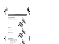
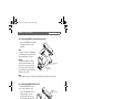
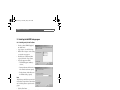
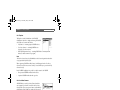
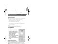
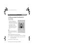
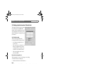
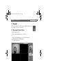
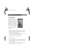
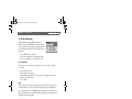
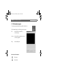
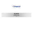
NetDVR.book Page i Wednesday, May 12, 2004 4:06 PM
NetDVR
User’s Guide
EN
NetDVR
NetDVR.book Page ii Wednesday, May 12, 2004 4:06 PM
NetDVR | User’s Guide
Bosch Security Systems | 2004-01
ii
NetDVR.book Page iii Wednesday, May 12, 2004 4:06 PM
NetDVR | User’s Guide | Contents
1.
INTRODUCTION .........................................................................................7
1.1
Description .................................................................................................7
1.2
Unpacking ..................................................................................................8
1.3
NetDVR Descriptions ..............................................................................8
2.
INSTALLATION .........................................................................................11
2.1
Installation summary .............................................................................. 11
2.1.1 System requirements ............................................................... 11
2.1.2 Recommended PC display settings ..................................... 11
2.1.3 Connecting Ethernet and power cables ............................. 11
2.1.4 Connecting NetDVR to a Hub on Internet or LAN ............ 12
2.1.5 Connecting NetDVR directly to a PC .................................. 12
2.1.6 Location ...................................................................................... 12
2.2
Installing the NetDVR Setup program .............................................. 13
2.2.1 Installing ‘setup’ for the first time .......................................... 13
2.2.2 Removing the program (Uninstall) ........................................ 14
2.3
NetDVR software ................................................................................... 14
2.4
Opening Configuration program ........................................................ 14
2.4.1 Explorer ....................................................................................... 15
2.4.2 Local Area Cameras ................................................................. 15
2.4.3 ‘My Cameras’ folder ................................................................. 16
2.4.4 Creating a new folder .............................................................. 16
2.4.5 NetDVR Registration in ‘My Cameras’ ................................. 16
2.4.6 Registering a NetDVR in remote Network .......................... 16
2.4.7 Registering a NetDVR in a local Network ........................... 17
2.4.8 WRS (Web Registration Server) .......................................... 17
3.
CONFIGURING THE NETDVR ...............................................................18
3.1
Log-in screen .......................................................................................... 18
3.2
Device Information (‘Information’ tab) ............................................... 18
3.2.1 Camera description .................................................................. 18
3.2.2 Camera setup shortcuts. ......................................................... 19
3.3
System setting information (‘System’ tab) ....................................... 19
3.3.1 Setting NetDVR time ............................................................... 19
3.3.2 Load default setup .................................................................... 19
3.3.3 Reboot Camera ......................................................................... 19
Bosch Security Systems | 2004-01
iii
NetDVR.book Page iv Wednesday, May 12, 2004 4:06 PM
NetDVR | User’s Guide | Contents
3.4
Setting Network Information (‘Network’ tab) ................................... 20
3.4.1 Ethernet ....................................................................................... 20
3.4.2 xDSL (PPPoE) ........................................................................... 20
3.4.3 DNS ............................................................................................. 20
3.4.4 WRS ............................................................................................ 21
3.4.5 Port assignment ........................................................................ 21
3.5
Setting up user accounts (‘User’ tab) ............................................... 22
3.5.1 Administrator .............................................................................. 22
3.5.2 Users ........................................................................................... 22
3.6
Setting Channel information (‘Channel’ tab) ................................... 23
3.6.1 Channel Use .............................................................................. 23
3.6.2 Camera Configuration ............................................................. 23
3.6.3 Motion Threshold ...................................................................... 23
3.6.4 PTZ ............................................................................................... 24
3.7
Setting Security information (‘Security’ tab) .................................... 25
3.7.1 Setting Security information ................................................... 25
3.8
Setting harddisk information (‘HDD’ tab) ......................................... 25
3.8.1 Auto Delete ................................................................................ 25
3.8.2 HDD Status ................................................................................ 26
3.8.3 How to format the HDD .......................................................... 26
3.9
Setting screen adjustment (‘Screen Adjustment’ tab) .................. 26
3.9.1 Screen settings ......................................................................... 26
3.10 Setting schedule information (‘Schedule’ tab) ............................... 27
3.10.1 Status bar-graph ....................................................................... 27
3.10.2 Post Alarm .................................................................................. 28
3.10.3 Time Table .................................................................................. 28
3.10.4 Normal Save ............................................................................... 28
3.10.5 Alarm Save ................................................................................. 29
3.10.6 Alarm Trigger ............................................................................. 29
3.10.7 Quality Box ................................................................................. 29
3.10.8 Setting up the output relay schedule ................................... 30
4.
MONITORING ...........................................................................................31
4.1
Opening the Live Viewer ...................................................................... 31
4.1.1 Selecting a NetDVR to view ................................................... 31
4.1.2 Login ............................................................................................ 32
Bosch Security Systems | 2004-01
iv
NetDVR.book Page v Wednesday, May 12, 2004 4:06 PM
NetDVR | User’s Guide | Contents
4.2
5.
4.1.3 Changing a password ............................................................. 32
4.1.4 Connecting ................................................................................. 32
Using the Live Viewer ........................................................................... 32
4.2.1 View quad monitoring screen ................................................ 32
4.2.2 View a specific channel ........................................................... 32
4.2.3 Quick recording ........................................................................ 33
4.2.4 PTZ functions ............................................................................ 33
4.2.5 Channel selection when PTZ is enabled ............................. 34
4.2.6 Alarm indicator .......................................................................... 34
4.2.7 Changing viewing resolution and frame rate ...................... 34
4.2.8 Disconnecting ............................................................................ 34
PLAYBACK ................................................................................................35
5.1
Opening the Playback Viewer ............................................................ 35
5.1.1 Select a NetDVR to playback ................................................ 36
5.1.2 Select a NetDVR to playback ................................................ 36
5.1.3 Changing a password ............................................................. 37
5.1.4 Connecting ................................................................................. 37
5.2
Using the Playback Viewer .................................................................. 37
5.3
Image Control panel .............................................................................. 38
5.4
Disk Control panel ................................................................................. 39
5.4.1 Delete Data ................................................................................ 39
5.4.2 Data Backup .............................................................................. 39
5.5
Playback Control .................................................................................... 40
5.5.1 Play Speed: ................................................................................ 40
5.5.2 Play Control Panel .................................................................... 41
5.5.3 Playback Time Select .............................................................. 41
5.6
Playback image monitoring ................................................................. 41
5.6.1 (1) Total recorded time indication ......................................... 41
5.6.2 (2) Scroll bar for selection of time and date ....................... 41
5.6.3 (3) Selected range indication ................................................ 41
5.6.4 (4) Hair line for frame movement ........................................... 42
5.6.5 (5) Total recorded status indication ..................................... 42
5.7
Disconnecting ........................................................................................ 42
5.8
Link to Live viewer ................................................................................. 42
Bosch Security Systems | 2004-01
v
NetDVR.book Page vi Wednesday, May 12, 2004 4:06 PM
NetDVR | User’s Guide | Contents
6.
FILE CONVERTER ....................................................................................45
6.1
Introduction ............................................................................................. 45
6.1.1 Image Format Conversion ....................................................... 45
6.1.2 Image Playback ......................................................................... 45
6.2
Installation ................................................................................................ 46
6.3
Starting the program ............................................................................. 47
Bosch Security Systems | 2004-01
vi
NetDVR.book Page 7 Wednesday, May 12, 2004 4:06 PM
NetDVR | User’s Guide | Introduction
1.
7
Introduction
1.1 Description
4-channel network DVR
NetDVR is a digital video recorder (DVR) that is controlled from a client PC through an
Ethernet connection using the TCP/IP protocol. The unit includes a Video compression
device, a Web server, a Networking interface and a hard disk (HDD). It requires up to four
external cameras, a power supply and a network connection to operate. The internal
settings allow the adaption of the unit for NTSC or PAL cameras.
Protected data on the HDD
NetDVR records and protects images on its HDD at a maximum speed of 30 frames (or
images) per second (fps). It incorporates a file system that prevents recorded data from
being damaged or lost in the event of sudden power failure. The HDD is built in an
externally accessible rack.
Efficient image compression
NetDVR utilizes Wavelet still image compressing. It has a 32-bit RISC CPU for more
efficient image processing.
Simple installation and additional functions
Its functional firmware is stored in an 8-MB flash memory chip. The firmware can be
upgraded remotely via Internet or Intranet. The NetDVR connects to external devices such
as sensors, pan/tilt mechanisms, zoom lenses, etc., via an HD-15 port (RS -232 & RS-485).
All external devices can be remotely controlled. The NetDVR controls 4 external CCD
cameras, (including existing analogue CCTV cameras) by connecting them to video input
ports.
HDD protection
The internal hard disk drive is of the same specification as used in laptop computers.
Therefore the NetCam DVR should be handled with care while in operation. Excessive
shock or vibration may cause a disk crash which damages the disk and causes loss of data.
Recommendation
Mount the NetDVR on a stable surface and avoid shock and vibration especially during
operation. Handle with care.
Indoor/Outdoor use
The operating temperature range of the NetDVR supports indoor application only.
Bosch Security Systems | 2004-01
NetDVR.book Page 8 Wednesday, May 12, 2004 4:06 PM
NetDVR | User’s Guide | Introduction
8
1.2 Unpacking
Unpack carefully and handle the electronic equipment with care to prevent damage. Check
for the following items:
•
•
•
•
•
•
NetDVR
Crossover cable, 1 m (red)
Direct cable 2 m (white)
Adapter and Power cable (12V DC, 3.5A)
Software
Manual
Note:
Save the packaging materials for future use if the unit needs to be shipped for service or repair.
1.3 NetDVR Descriptions
BOSCH
1
Front View:
Operation:
Video Input:
Sensor Input:
Alarm Output:
A
PWR
= Power ON indicator
RUN
= Internal processor is working when ON
REC
= Unit is recording when ON
CMPR = Unit is compressing images when ON
Indicator is ON for the enabled video input channels
Indicator is ON when event is detected on the input
Indicator is ON when relay output is active
1. Hard Disk Rack with lock (A).
Rear View:
2.
3.
4.
5.
6.
7.
8.
Relay output (Alarm Out).
Sensor input.
Serial communication (RS232, RS 485, RS 422).
Base band video inputs.
Video input termination switch.
Ethernet Network.
Power supply input, 12Vdc, 3.5A.
2
3
4
5
6
Bosch Security Systems | 2004-01
7
8
NetDVR.book Page 9 Wednesday, May 12, 2004 4:06 PM
NetDVR | User s Guide | Introduction
9
Re lay ou tput (ALARM OUT):
Solid-state relay output, normally open
contacts. Max . 250VAC or 250VDC, 170mA.
AL
O1
+
-
AR
M
O2
+
-
OU
O T
+
3
O4
-
+
-
Senso r Input:
Opto-coupler alarm sensor inputs. Internal
Pull-up to +5VDC
S1
+
SE
NS
S2
-
+
OR
IN
S3
-
+
S4
-
+
Input closed: No event
Input open: Event
Serial Commu nication :
RS-232:
To communicate with external PTZ
controlled CCTV cameras. These
pins are for devices that comply
with RS-232C. Connect pins Rx, Tx
and G (ground).
RS-422:
To communicate with external PTZ
controlled CCTV cameras that
satisfy RS-422 protocol, half-duplex.
It is connected to R+, R-, T+, and
T-.
RS-485:
Alternative communication port
for BOSCH AutoDome versions
with RS485 port. Use T+ and Tto make the two wire connection.
Bosch Security Systems | 2004-01
SE
RS
RX
RIA
23
2
TX
G
LC
OM
RS
R+
M.
42
R-
2/4
8
T+
T-
5
-
NetDVR.book Page 10 Wednesday, May 12, 2004 4:06 PM
NetDVR | User’s Guide | Introduction
10
Base band video inputs
Analogue video inputs for NTSC or PAL signals on BNC. The 4 inputs can be terminated
into 75 Ohms or High impedance for loop trough. Use a BNC T-piece for the loop through
connection.
Termination Switches
Switch Function
The switch number corresponds with the input
channel number. Put the switch in the down
position (75 Ohm) to terminate the input or in
the up position for high impedance loop
through.
Network
Connect to the Ethernet network using a RJ45
UTP connector. Communication is on 10baseT
- TCP/IP protocol.
DC12V
Power supply connector, 12Vdc 3.5A with
5mm connector, positive voltage on the center
pin.
Bosch Security Systems | 2004-01
IMPEDANCE
SELECT SW
Ch
1
1
Ch
2
Ch
3
2 3 4 HI-Z
Ch
4
75ohm
NetDVR.book Page 11 Wednesday, May 12, 2004 4:06 PM
NetDVR | User’s Guide | Installation
11
2. Installation
2.1 Installation summary
Installation of the NetDVR consists of the following basic steps:
•
•
•
•
•
•
Connect the NetDVR onto a local Ethernet network and connect power.
Install the NetDVR software on a PC.
Configure the Administrator’s settings.
Configure the recording and search options.
Mount the NetDVR in the correct location and re-connect the power and Ethernet.
Connect the external cameras.
Installation details are given in the following paragraphs:
2.1.1 System requirements
For NetDVR you need:
•
Network: 10 Base-T LAN.
For a PC to access NetDVR:
•
•
•
•
•
CPU: Pentium II or above
Minimum free RAM: 64MB
Operating system: Windows 98, 2000, ME, NT4 or XP
Network interface card: 10 base-T or dual speed 10/100 base-T with TCP/IP enabled.
16 MB video memory or more.
2.1.2 Recommended PC display settings
Using the Windows ‘Setting / Control Panel / Display’ options:
•
•
Set color option to ‘High color (16-bit)’ or above.
Set screen resolution to 1024x768 pixels (minimum).
2.1.3 Connecting Ethernet and power cables
•
•
•
Connect an Ethernet LAN cable to the ‘Ethernet’ port (RJ-45 connector) on the rear
panel.
Connect the power supply (12V, 3.5A adaptor, supplied) to the connector marked ‘DC
12V’.
Confirm that the green LED on the Ethernet port flashes every 1 to 2 seconds. Note that
it starts flashing 5 to 6 seconds after applying power.
Bosch Security Systems | 2004-01
NetDVR.book Page 12 Wednesday, May 12, 2004 4:06 PM
NetDVR | User’s Guide | Installation
12
2.1.4 Connecting NetDVR to a Hub on Internet or LAN
•
Connect the NetDVR to the network
hub using the white direct cable
(supplied).
Note:
A remote user cannot access the NetDVR until its
network settings have been assigned. It requires
an unoccupied IP address to be assigned.
B
HU
DC 12V
Caution:
Do not use the default IP address. Within a
closed network, random IP addresses may be
assigned as long as each one is unique. For a
private network connected to the Internet, a
registered IP address is required (available from
your Internet service provider).
POWER SUPPLY
TO AC OUTLET
(SUPPLIED)
ETHERNET
DIRECT CABLE
(SUPPLIED)
Note:
The network address of the local user and that of the NetDVR must be within the same network segment.
2.1.5 Connecting NetDVR directly to a PC
To configure the NetDVR locally, it
can be connected directly to a PC.
•
ETHERNET
CROSS OVER CABLE
Connect the NetDVR to the PC’s
LAN port using the crossover
cable (cable with red connectors,
supplied). Ensure that the local PC
and NetDVR both have their
network address set within the
same network segment.
(SUPPLIED)
DC 12V
POWER SUPPLY
(SUPPLIED)
TO AC OUTLET
2.1.6 Location
•
Place the NetDVR appropriately
for your purpose. Mount the NetDVR on a stable surface and avoid shock and vibration
especially during operation.
MAC address
The 12-digit MAC address of the NetDVR is on a label on the bottom. To correctly enter
this address using the ARP command, enter the “-” as separator to form a string of 6 twodigit characters, i.e. 00408C100086 becomes 00-40-8C-10-00-86.
Bosch Security Systems | 2004-01
NetDVR.book Page 13 Wednesday, May 12, 2004 4:06 PM
NetDVR | User’s Guide | Installation
2.2 Installing the NetDVR Setup program
2.2.1 Installing ‘setup’ for the first time
•
•
•
•
•
Insert the software CD-ROM (supplied)
into the PC’s drive.
Copy ‘Setup.exe’ onto the PC’s desktop.
Double click on ‘Setup.exe’ on the desktop
to activate the setup program.
Read the license conditions and, when
accepted, click on the ‘I agree’ button.
Select the components to install:
• The NetDVR program (mandatory
selection)
•
Start menu shortcuts, which insert icons
in the Windows start menu (optional)
•
Desktop shortcuts, which adds icons to
the Windows desktop (optional).
Note:
The default setting is with all three components selected.
De-select what is not required. However, either the ‘Start
menu’ or the ‘desktop Shortcuts’ is required to start the
program.
•
•
Click the ‘Next’ button.
Select a directory to install the program to, if needed.
Note:
The default is 'D:\Program Files\Bosch\NetDVR’, where D: is the disk holding the operating system.
•
Click the ‘Finish’ button to complete the installation.
If ‘Desktop shortcuts’ has been selected, the
following three icons appear on the desktop:
•
•
•
‘NetDVR Configuration’ provides access to
administrator’s settings (refer to section 3)
‘NetDVR Monitor’ opens the monitor
window (view only, no playback functions,
refer to section 4)
‘NetDVR Playback’ opens the Playback
window (with a link to the monitor, refer to
section 5)
Bosch Security Systems | 2004-01
13
NetDVR.book Page 14 Wednesday, May 12, 2004 4:06 PM
NetDVR | User’s Guide | Installation
2.2.2 Removing the program (Uninstall)
To uninstall the program:
• Select ‘Uninstall’ in the Windows start menu.
Or
•
Use the Windows Control Panel’s ‘add/remove programs’ utility to uninstall the
NetDVR.
2.3 NetDVR software
NetDVR comprises three software programs:
•
•
•
Configure: to setup the NetDVR system parameters.
Monitor: to monitor real-time images.
Playback: to search and playback recorded images and backup files.
2.4 Opening Configuration program
Click on the ‘NetDVR Configuration’ icon on the desktop or on the link in the
Start menu.
Enter your password (default: admin).
To change the password, click on the ‘Edit’
button.
First enter the current password, next enter the
new password and enter the same new
password again to confirm.
Bosch Security Systems | 2004-01
14
NetDVR.book Page 15 Wednesday, May 12, 2004 4:06 PM
NetDVR | User’s Guide | Installation
15
2.4.1 Explorer
The Explorer is in the left hand frame of the ‘NetDVR
ConfigStation’ and used to configure and manage all NetDVR
device addresses. It contains three folders:
•
•
•
‘My Cameras’ – containing registered NetDVR devices.
‘Local Area Cameras’ – containing NetDVR devices
detected in a local area network.
‘WRS’ (Web Registration Server) – containing NetDVR devices with a dynamic IP
address (for future extension of the program).
Note:
The ‘Local Area Cameras’ directory lists all NetDVR devices on the local network segment that are detected but
not yet registered in the ‘My Cameras’ folder.
When registering a NetDVR onto ‘My Cameras’, it will disappear from the ‘Local Area
Cameras’ directory. Remote cameras can only be viewed when they are present in the ‘My
Cameras’ directory
In the ‘NetDVR ConfigStation’ it is possible to verify the status of each NetDVR:
•
•
Non-operational NetDVR is indicated with a red dot.
Operational NetDVR is indicated with a green dot.
2.4.2 Local Area Cameras
All NetDVR devices on the Local Area Network and in the
same segment of the client PC are visible in the Local Area
Cameras folder. These non-registered cameras are identified by
their IP address. If the IP address is outside the local network
segment address range it cannot be accessed. In order to make
the device accessible, change the IP address to a free local
address:
•
•
•
•
Right click on IP address of the NetDVR device.
Click ‘Change IP’
Enter the Administrator’s password of the device and change
IP address.
Click OK to confirm.
Bosch Security Systems | 2004-01
NetDVR.book Page 16 Wednesday, May 12, 2004 4:06 PM
NetDVR | User’s Guide | Installation
16
2.4.3 ‘My Cameras’ folder
Transferring a NetDVR from the ‘Local Area Cameras’ folder to the ‘My Cameras’ folder
makes it possible to rename it and use a Nickname to open the connection. NetDVR
devices on a remote Network can only be registered onto this folder.
When registering a NetDVR, the relevant address information of the selected device is
stored in the PC. This makes it possible to access a registered NetDVR without being in the
same local network.
2.4.4 Creating a new folder
By creating folders and registering the appropriate NetDVR devices in each folder, it is
easier and more convenient to manage multiple devices. To register folders:
•
•
•
•
•
Move the mouse cursor over ‘My Cameras’.
Click the right hand mouse button.
Select ‘New Folder’ from the pop-up menu - a dialogue box pops up to enter a new
folder name.
Enter the name and press ‘OK’ button to create a new folder.
To delete a registered folder, select ‘Delete Folder ’ in the pop-up menu.
2.4.5 NetDVR Registration in ‘My Cameras’
There are two methods of registering a NetDVR into the ‘My Cameras’ folder (or subfolders); one for remote networks, and the other for local networks.
2.4.6 Registering a NetDVR in remote Network
•
•
•
•
•
Move the mouse cursor over ‘My Cameras’.
Click the right button of the mouse.
Select 'Add Cam’ - a dialogue box pops up
to enter the IP address of the remote
NetDVR.
Press the ‘Start Probe’ button, and when
found the NetDVR is automatically
registered.
To delete a registered NetDVR, select
‘Delete Cam’ in the pop-up menu.
Note:
The name of a registered NetDVR may have up to 30 English characters or numbers. NetDVR with a dynamic
IP are registered in the ‘WRS’ folder (this option is for future extension).
Important: For easy access to a remote or local NetDVR always use it on a fixed IP
address.
Bosch Security Systems | 2004-01
NetDVR.book Page 17 Wednesday, May 12, 2004 4:06 PM
NetDVR | User’s Guide | Installation
17
2.4.7 Registering a NetDVR in a local Network
•
•
Drag a NetDVR from the ‘Local Area Cameras’ directory onto the ‘My Cameras’
directory or a sub-folder.
To unregister, drag it from ‘My Cameras’ into the ‘Local Area Cameras’ directory. The
nickname is replaced by the IP address.
2.4.8 WRS (Web Registration Server)
When a NetDVR is connected via ISDN, xDSL, or cable modem, its IP address may
change whenever it reconnects to the Internet service provider. In this case, users don’t
know the IP address so cannot access the NetDVR. This is why a WRS (Web Registration
Server) is necessary. A NetDVR with dynamic IP is registered to the WRS server to make it
easy for users to find the changed IP address and to access it.
Note:
The WRS option requires a server with the WRS software installed. Please contact your reseller for
information.
Bosch Security Systems | 2004-01
NetDVR.book Page 18 Wednesday, May 12, 2004 4:06 PM
NetDVR | User’s Guide | Configuring the NetDVR
18
3. Configuring the NetDVR
Select the NetDVR in the explorer frame of the ‘NetDVR ConfigStation’ window.
•
Click the IP address or the Nickname.
3.1 Log-in screen
To enter the NetDVR’s parameter set-up:
•
Enter the administrator’s Password of the
device.
Note:
Entry to the configuration settings of the NetDVR is
possible only with the administrator’s password. The
default password of the NetDVR is ‘admin’.
If ‘Save Password’ is checked, it is not
necessary to enter the Password every time you
log in. ‘Save Password’ function can only be
utilized if the NetDVR is registered on the ‘My
Cameras’ folder.
• Click on the “Login” button.
or
•
Click on the “Configure” button to re-enter
the configuration program when the password is still valid.
or
•
Click on the “Exit” button to terminate the configuration program.
3.2 Device Information (‘Information’ tab)
The ‘Information’ tab displays setting information for the selected camera. The following
are set up when the camera is manufactured and cannot be changed:
•
•
•
•
•
Model name
Hardware version
Software version
Serial number
Mac Address
3.2.1 Camera description
The ‘Description’ may be changed using up to 30 English characters and/or numbers. To
change the description:
•
•
•
Click on the cell to the right of ‘Description’ (the default text is ‘Welcome’).
Type in the new description and press the ‘Enter’ key.
Click ‘Apply’ to upload the new setting in the NetDVR.
Bosch Security Systems | 2004-01
NetDVR.book Page 19 Wednesday, May 12, 2004 4:06 PM
NetDVR | User’s Guide | Configuring the NetDVR
19
3.2.2 Camera setup shortcuts
The main information about the current setup is displayed for the connected NetDVR. This
screen provides a shortcut for the blue items in the list; to change the settings:
•
•
•
Double-click the required item to open its configuration Tab.
Enter the settings in the dedicated configuration screen.
Click the ‘Apply’ button to store the new settings and click the ‘Information’ tab and
select the next item if required.
3.3 System setting information (‘System’ tab)
3.3.1 Setting NetDVR time
The NetDVR has an internal real-time clock with
time zone adjustment. To set the time and date:
•
•
•
•
•
Select the time zone from the pull down menu.
Check the Daylight Saving Time box to activate
DST (DST is automatically changed).
Select the date from the calendar.
Enter the ‘Current time’ (the new time is validated
as soon as the Apply button is clicked).
Click the “Apply” button to upload the settings to
the NetDVR.
Using NTP (Network Time Protocol)
The NTP protocol is compatible with the Windows
SNTP time function and enables synchronization of the NetDVR clocks in a network.
NTP mode: Select Client to receive time information from the time server. Select Server to
configure this NetDVR as time server. All other devices are clients and synchronize time
with this server.
Interval: Select the interval that the clock will be synchronized.
IP type: Select "Local IP" for using a local time server or "Public IP" to use a time server on
the Internet (NetDVR connects automatically to one of 59 preprogrammed time servers).
Local IP: Enter the IP address of the local Time Server (either a NetDVR configured as
time server or a Network PC with Windows Time Server enabled).
3.3.2 Load default setup
Resets the configuration to factory defaults (excluding time and network configurations):
•
Click on the ‘Start’ button to the right of ‘Load Setup Defaults’.
3.3.3 Reboot Camera
If the NetDVR has a problem, reboot it without interrupting the power supply as follows:
•
Click on the ‘Start’ button to the right of ‘Reboot Camera’.
Bosch Security Systems | 2004-01
NetDVR.book Page 20 Wednesday, May 12, 2004 4:06 PM
NetDVR | User’s Guide | Configuring the NetDVR
20
Note about time overlap
After the time setting for the NetDVR has been adjusted, there may be an overlap of time
settings of previously recorded images with newly recorded images. To avoid deletion of
images, the frames with the same new time are recorded next to the previous ones. Frames
with the same time settings appear red in the playback bar and playback reverts back to the
time settings again to playback the second set of images with identical time settings.
3.4 Setting Network Information (‘Network’ tab)
3.4.1 Ethernet
The ‘Ethernet’ section of the ‘Network’ tab
allows the IP address, Network Mask, Gateway
address and DNS server addresses to be set
manually.
Note:
There is no field for Broadcast address
configuration because this is configured
automatically. If the addresses are incorrectly
assigned, the NetDVR cannot be accessed.
The DHCP (Dynamic Host Configuration
Protocol) is for the Network administrator to
automatically assign IP addresses to the
connected network devices. It is only used in
combination with the optional WRS feature. If
the administrator checks the ‘DHCP Enable’
option, IP address in the NetDVR is
automatically set; the IP address will not be
shown.
3.4.2 xDSL (PPPoE)
When using a xDSL connection with PPPoE login, check the xDSL box and enter the User
ID and Password needed to login on the Internet account.
3.4.3 DNS
The DNS section of the ‘Network’ tab is used when a NetDVR is registered on the dynamic
IP registration list of a WRS (Web Registration Server). Enter the address of the WRS server
in the DNS fields.
Bosch Security Systems | 2004-01
NetDVR.book Page 21 Wednesday, May 12, 2004 4:06 PM
NetDVR | User’s Guide | Configuring the NetDVR
21
3.4.4 WRS
When a NetDVR is connected via ISDN, xDSL or a cable modem, its IP address changes
whenever it reconnects to the Internet service provider. In this case, users don’t know the IP
address and thus cannot access the NetDVR. This is why the WRS (Web Registration
Server) is necessary. Connection to the NetDVR is then done via the WRS services.
•
•
Registration Interval: Enter the time interval for automatic registration of the NetDVR’s
IP address at the WRS server.
Registration Server and Group ID: This is to enter your own server and group ID on the
WRS. The ‘Group ID’ is used for organizing the NetDVR devices in groups on the
WRS.
Note:
This function requires installation of a separate WRS server with dedicated software.
3.4.5 Port assignment
The ‘Port Assignment’ section of the ‘Network’
tab is to configure Playback port and
Monitoring port when a firewall is present in
the network.
•
•
•
Select ‘Normal’ for networks without a
firewall.
Select ‘Firewall’ for networks with a firewall
Click on 'Advanced’ to manually set the
playback and monitoring port.
Note:
The Viewer program uses port 8105 as playback port
and port 8001 as monitoring port for surveillance. If the
ports are blocked on the network, available ports should
be entered manually. The changed value is effected after
rebooting. To return to defaults, click on the ‘Default’
button, and the changed value is reconfigured as the
default values (8105 and 8001). The firewall function
uses port 80, which is normally open for browsing the
Internet. Using this port for playback and monitoring
may slow down the frame rate.
Click the “Apply” button to upload the settings
into the NetDVR.
Bosch Security Systems | 2004-01
NetDVR.book Page 22 Wednesday, May 12, 2004 4:06 PM
NetDVR | User’s Guide | Configuring the NetDVR
22
3.5 Setting up user accounts (‘User’ tab)
3.5.1 Administrator
The 'Administrator’ has default access to all
NetDVR functions.
•
•
•
•
The Administrator’s user name is fixed as
‘admin’.
The default Administrator’s password in
‘admin’. The password should be changed
for security reasons, to change the
password:
Type the new password in the ‘Password’
field.
Retype the new password in the ‘RePasswd’ field.
3.5.2 Users
A general user may monitor real-time images plus search and view recorded images when
authorized to do so by the administrator. The administrator sets the user names and
passwords.
•
•
•
•
Check the User1, User2, User3 or User4 boxes to enable up to four users.
Default user names are User1, User2, User3 and User4 respectively (these names can be
changed).
Type the new password in the ‘Password’ field.
Retype the new password in the ‘Re-Passwd’ field.
User authorization:
•
•
•
•
Check Channels 1, 2, 3 and/or 4 to authorize a user to access the images of the
respective channels.
Check the ‘PTZ’ box to give the user access to pan/tilt/zoom controls in the Monitor
program.
Check the ‘HDD’ box to give the user access to search and playback functions in the
Playback program.
Check the ‘DEL, box to give the user access to deleting recorded images using the
Playback program.
Click the “Apply” button to load the settings in the NetDVR.
Bosch Security Systems | 2004-01
NetDVR.book Page 23 Wednesday, May 12, 2004 4:06 PM
NetDVR | User’s Guide | Configuring the NetDVR
23
3.6 Setting Channel information (‘Channel’ tab)
3.6.1 Channel Use
The ‘Channel’ tab function configures channels
to view live images and to record them on the
NetDVR’s internal HDD.
•
Select one or more channels (Channel 1– 4)
as video source(s).
Note:
It is very important to select only the channels that have
an external camera connected. Otherwise recording speed
or transmission speed may be slower.
3.6.2 Camera Configuration
In the ‘Camera Configuration’ section the cameras type is defined:
•
•
•
Check ‘NTSC’ or ‘PAL’ according to TV standard of the connected cameras.
Check ‘Rotation 180°’ to rotate an image by 180° (if camera is mounted upside-down, for
example, suspended from a ceiling).
Check ‘B&W’ if a monochrome (black and white) camera is used.
3.6.3 Motion Threshold
The ‘Motion Threshold’ function sets the motion detection threshold.
The range is from 1 to 999. An entry of ‘1’ is the lowest threshold giving highest sensitivity,
and ‘999’ is the highest threshold giving the lowest sensitivity. The default value is ‘500’.
Bosch Security Systems | 2004-01
NetDVR.book Page 24 Wednesday, May 12, 2004 4:06 PM
NetDVR | User’s Guide | Configuring the NetDVR
24
3.6.4 PTZ
The ‘PTZ’ section sets up the drivers for a pan/
tilt/zoom control mechanism, if installed.
To install click the ‘Setup’ button and configure
the following:
•
•
Model: At present, NetDVR is supplied
with some protocols for specific models of
pan/tilt mechanisms (which can be selected
from the pull down menu).
Select communication protocol and enter
this is the appropriate fields:
• Interface: NetDVR has two sets of interface pins: the RS232 interface and the RS485
(half-duplex) interface. Select the appropriate interface for which the pan/tilt/zoom
control receiver is connected to NetCam-DVRII.
•
Baud: Configures data transmission rate (from the pull-down list).
•
Parity: Checks data loss for transmission (from the pull-down list).
•
Stop bit: Configures stop bit for transmission (from the pull-down list).
•
Data bit: Configures data bit for transmission (from the pull-down list).
•
Address: This field identifies the base address of the pan/tilt/zoom (P/T/Z) control
receiver for the select video channel.
Note:
Settings for Bosch and Philips Autodome devices: Interface: RS232, Baud: 9600, Parity: None, Stopbit: 1,
Address: address of the PTZ device, and Databit: 8. The NetDVR may support up to four PTZ devices for four
separate channels. Use the RS232-to-bi-phase converter to connect and address the four devices.
Click the “Apply” button to upload the settings into the NetDVR.
Bosch Security Systems | 2004-01
NetDVR.book Page 25 Wednesday, May 12, 2004 4:06 PM
NetDVR | User’s Guide | Configuring the NetDVR
25
3.7 Setting Security information (‘Security’ tab)
3.7.1 Setting Security information
Access to specific IP addresses can be allowed
or denied.To set security information:
•
•
•
•
Select ‘IP Filtering’.
Enter the range of IP addresses to be
allowed or denied access.
Select ‘Allow’ to allow access of the entered
ranges of IP addresses. All other addresses
are denied access.
Select ‘Deny’ to prohibit access of the
entered ranges of IP addresses. All other
addresses are granted access.
Note:
The IP filtering is applied to the whole range of entered IP addresses. For example, if you configure
‘192.168.1.99 to 192.168.1.101’ and ‘192.168.1.150 to 192.168.1.160’ as ‘Deny’, the relevant IP users
cannot access the NetDVR. If you wish to allow or deny access to just one IP address, enter the IP address as a
range in the form ‘192.168.1.100-192.168.1.100’.
You can enter the ranges of IP addresses in 10 statements.
Click the “Apply” button to upload the settings into the NetDVR. Setting harddisk
information (‘HDD’ tab)
3.8 Setting harddisk information (‘HDD’ tab)
3.8.1 Auto Delete
The ‘Auto Delete’ function automatically
deletes data by 1000, 2000, 5000 or 10000
frames when the HDD is full. By default, the
earliest recorded frames are deleted. When
activating this function, the NetDVR will be in
a loop recording mode by using the space of
the deleted images. If this Auto Deletion
feature is disabled, the NetDVR stops
recording when the HDD is full.
Note:
If an administrator or authorized user manually deletes
data on the HDD using the ‘Playback’ program while
another user is searching on the HDD, the
PlaybackViewer displays an ‘Auto Delete [number]’ message to the other user (‘number’ indicates number of
deleted image frames).
Bosch Security Systems | 2004-01
NetDVR.book Page 26 Wednesday, May 12, 2004 4:06 PM
NetDVR | User’s Guide | Configuring the NetDVR
26
3.8.2 HDD Status
The pie diagram shows the Hard Disk Drive’s free space.
HDD Enable:
•
•
If the ‘HDD Enable’ box is checked, the NetDVR will record images on its HDD as
selected in the ‘Schedule’ tab.
If the ‘HDD Enable’ is not selected, the NetDVR will neither record nor playback. The
default value is ‘Enabled’.
3.8.3 How to format the HDD
It is possible to (re-)format the HDD using the following procedure:
Caution: When HDD is formatted, all recorded images are deleted.
•
•
•
•
•
•
•
Start ‘NetDVR Configuration’.
Click on the ‘HDD’ tab in the ‘Configuration’ program.
Disable the HDD and click on the ‘Apply’ button.
Select ‘HDD Enable’ but don’t click the ‘Apply’ button yet.
When the ‘HDD Format’ button is activated again, click the ‘HDD Format’ button.
Confirm the request to format the HDD.
When the HDD is formatted, click on the ‘HDD Enable’ button and next the ‘Apply’
button.
Note:
If the administrator formats the HDD from the ‘Setup’ program while another user uses is searching on the
HDD, Playback Viewer displays the message: 'HDD is to be formatted now by a administrator. Connection
will be closed. Please reconnect later’. The connection of the other user is then closed.
Click the “Apply” button to upload the settings into the NetDVR.
Bosch Security Systems | 2004-01
NetDVR.book Page 27 Wednesday, May 12, 2004 4:06 PM
NetDVR | User’s Guide | Configuring the NetDVR
27
3.9 Setting screen adjustment (‘Screen Adjustment’ tab)
3.9.1 Screen settings
To adjust the video image:
•
•
•
Select the ‘Screen Adjustment’ tab.
Adjustment in this menu affects both the
live image and the recorded image displays.
Select the channel to be adjusted.
Adjust the brightness, contrast, hue,
saturation, horizontal offset as required to
balance the images as they appear on
screen.
Note:
Depending on model the Horizontal Offset and Video
Gain may be automatic and not adjustable. The controls
are then grayed out.
Brightness: Adjusts the lightness/darkness of the screen image.
Contrast: Adjusts the ratio between dark and bright parts of the image (soft or hard image).
Hue:
For NTSC cameras adjust until the white image areas appear white. For PAL
leave the adjustment at default.
Saturation: Adjusts the color brightness of the image.
Click the “Apply” button to upload the settings into the NetDVR.
Bosch Security Systems | 2004-01
NetDVR.book Page 28 Wednesday, May 12, 2004 4:06 PM
NetDVR | User’s Guide | Configuring the NetDVR
28
3.10 Setting schedule information (‘Schedule’ tab)
The settings in ‘Schedule’ are used to program
the recording status of the NetDVR. The
schedule setup of the individual channels and
of the output relays is done in their respective
windows. Clicking on the “Setup” button opens
these windows.
3.10.1 Status bar-graph
The horizontal bar graph indicates the
recording time schedule and status as follows:
•
•
•
As recording rate gets higher, the color
becomes denser.
There are two bars for each channel, one to
indicate the configuration of the normal
recording schedule (top), and the red one
to indicate the event condition (bottom).
A blue vertical bar indicates the current
time of the NetDVR.
External Sensor Input Devices
The Sensor input devices can be selected trigger event recording.
To enable the (alarm) sensor input ports:
•
Check the relevant boxes to enable the devices.
Note:
The NetDVR supports normally-closed (NC) type sensors only. These option check boxes only configure which
type of external device is used. The functions controlled by the relevant external device are configured in the
separate ‘Setup’ screens as detailed below.
The sensor (alarm) inputs comprise LED type photo-couplers. The inputs contacts must be
normally closed. Opening the input contact generates an alarm trigger.
Specification of the input: Input pull-up to 5 Vdc for an open input, current 12 mA for
closed contact.
3.10.2 Post Alarm
This function determines how long an image will be recorded after an alarm triggered event
has occurred. Valid entries are between 0 and 60 seconds.
Click the “Apply” button to upload the settings into the NetDVR.
Setting up a recording schedule:
•
Click on the ‘Setup’ button for the channel to be configured.
Bosch Security Systems | 2004-01
NetDVR.book Page 29 Wednesday, May 12, 2004 4:06 PM
NetDVR | User’s Guide | Configuring the NetDVR
29
Note:
Repeat for each channel to configure all relevant schedules. Each channel can have its own timetable.
3.10.3 Time Table
•
A day can be divided into 5 time zones
between 0:00 and 24:00. If you configure
the first time zone to be only part of a full
day, the following time zone will be
activated. Note that zone 5 automatically
fills in the remainder of the day.
3.10.4 Normal Save
Normal Save defines recording parameters for
normal (not event-triggered) recording as
follows:
•
•
•
Set the ‘frame rate’ using the pull-down list
(the higher the rate, the less ‘jumpy’ the
picture).
Set the ‘resolution’ using the pull-down list
(the higher the resolution, the more detail
that is visible).
Set the ‘quality’ (compressing rate) using
the pull-down list (choosing lower image
quality results in a higher compression rate
and smaller file size).
3.10.5 Alarm Save
Event Save defines the recording parameters for an event-triggered situation as follows:
•
•
•
Set the ‘frame rate’ using the pull-down list (the higher the rate, the less ‘jumpy’ the
picture).
Set the ‘resolution’ using the pull-down list (the higher the resolution, the more detail
that is visible).
Set the ‘quality’ (compressing rate) using the pull-down list (choosing lower image
quality results in a higher compression rate and smaller file size).
3.10.6 Alarm Trigger
The alarm trigger defines which events trigger the 'Alarm Save’ function. The Relay Output
trigger schedule is setup in the Relay Setup screen.
Bosch Security Systems | 2004-01
NetDVR.book Page 30 Wednesday, May 12, 2004 4:06 PM
NetDVR | User’s Guide | Configuring the NetDVR
•
•
If the motion detect ‘MD’ or a sensor (S1~S4) check box is selected, the image is
recorded on the HDD with the 'Alarm Save’ setting, when that device triggers the alarm.
Select the event devices for each of the five Time Table sections.
3.10.7 Quality Box
The quality box allows for selecting the area of
interest to full image quality (focus area) while
the remainder of the image is reduced in
contrast to reduce the amount of data to be
stored or transmitted.
•
•
•
•
•
Click on the large button to open the
Quality Box configuration window.
A quality box is configured by drawing a
rectangular area in the image.
Move the mouse over the border and click
to resize or move inside the QBOX, click
and move the box.
To clear a configured quality box, click the
mouse button out of selected area.
Set the 'Attenuation level’ (1 to 5) to
determine the contrast of the image outside
the ‘focus area’.
Note:
Selecting attenuation level ‘1’ means the contrast level outside the ‘ focus area’ is almost the same as that
within the ‘focus area’. Selecting level ‘5’ means the image outside the ‘focus area’ is dark.
•
•
30
Click on the OK button to enter the quality box settings.
Check the quality box checkboxes for the time zones as required.
Click on the OK button to confirm the settings and return to the ‘Schedule’ main screen
Bosch Security Systems | 2004-01
NetDVR.book Page 31 Wednesday, May 12, 2004 4:06 PM
NetDVR | User’s Guide | Configuring the NetDVR
3.10.8 Setting up the output relay schedule
Click the “Relay” Setup button.
Time Table
•
•
•
A day can be divided into 5 time zones
between 0:00 and 24:00. The time zones
for the relay output can have its own
schedule or the schedule of (one of) the
channels can be entered.
First define which Relay must be operated
manually from the Live Viewer. The
manual selection is exclusive for that relay
output; all other check boxes are disabled.
Fill in the matrix of alarm trigger inputs
‘Motion Detect CH1 ~ CH4’ or ‘Sensor
Input 1 ~ Input 4’.
Click on the OK button to confirm the settings and return to the ‘Schedule’ main screen.
Click the “Apply” button to upload the settings into the NetDVR.
Bosch Security Systems | 2004-01
31
NetDVR.book Page 32 Wednesday, May 12, 2004 4:06 PM
NetDVR | User’s Guide | Monitoring
4. Monitoring
4.1 Opening the Live Viewer
To open the Live Viewer:
• Click on the ‘NetDVR Monitor’ icon on the desktop.
Or
•
•
Click on the ‘NetDVR Monitor’ icon in the
Windows Start menu
>>Programs>>Bosch>>NetDVR Monitor.
The real-time Live Viewer opens.
Note:
Holding the mouse pointer over a button will reveal the
function of that button in a pop-up box.
4.1.1 Selecting a NetDVR to view
If a NetDVR is already selected, its nickname or
IP Address is shown in the address field (top
right).
•
•
Reconnect by clicking the ‘Connect’ button.
Enter the User Name and Password of the
device and click on the OK button.
To select a NetDVR (if no selection is already
shown) or to change a selection:
•
•
•
•
Click on the ‘Select Camera’ button to open
the Explorer.
Expand the ‘My Cameras’ or ‘Local Area
Cameras’ folders by clicking the [+] in front
of the name to list the installed devices.
Select a NetDVR by double-clicking on its
name or by clicking the name once and then
clicking on the ‘OK’ button.
After a NetDVR has been selected its IP
address or ‘Nick Name’ is displayed in the
address field.
Bosch Security Systems | 2004-01
32
NetDVR.book Page 33 Wednesday, May 12, 2004 4:06 PM
NetDVR | User’s Guide | Monitoring
33
4.1.2 Login
•
Enter the User Name and Password of the selected NetDVR and click the OK button.
4.1.3 Changing a password
The Login screen allows the User’s Password to
be changed.
•
If the selected NetDVR is registered, the
‘Change Password’ check button is active.
Note:
The User ID of the previous user is shown in ‘User
Name’.
A user may change their password using up to
14 English characters or numbers. The
Administrator’s Password can only be changed
in the Configuration program. To change a user password:
•
Click on ‘Change password’ and follow on-screen instructions
4.1.4 Connecting
The program connects the NetDVR after
successful login.
For reconnection after transmission interruption, ensure the Name is displayed in the
address field.
•
Click on the ‘Connect’ button.
4.2 Using the Live Viewer
4.2.1 View quad monitoring screen
• Click the quad icon (bottom left of screen).
Or
•
Double-click on the single image.
4.2.2 View a specific channel
• Click on the relevant Camera View icon (bottom left of screen).
Or
•
Double-click on one of the four images in the quad monitoring screen (see also ‘Channel
selection when PTZ is enabled’)
Bosch Security Systems | 2004-01
NetDVR.book Page 34 Wednesday, May 12, 2004 4:06 PM
NetDVR | User’s Guide | Monitoring
34
4.2.3 Quick recording
When monitoring real-time images, you can
record specific images to the PC’s hard disk.
To record from the Live Viewer:
•
•
•
•
Click on the red ‘Rec’ button (or press
‘Ctrl’+S).
A dialogue box opens that provide
information about the recording.
The Quick recording process ends
automatically after 5 minutes (unless user
stops it earlier by clicking on the ‘Stop’
button).
After the recording process is finished
completely, the user is prompted to enter a
file name and directory to save on the PC’s disk.
Note:
When the Quick recording process finishes normally, the Playback program is automatically started for
immediate replay of the file. If the Playback Viewer is already open, a second Playback Viewer will be started.
4.2.4 PTZ functions
A user authorized for PTZ may control the
Pan/tilt/zoom functions. To do so:
•
•
•
Place mouse cursor over the image.
A dotted cross line appears on the center
with control bars on each side of the image.
Zoom & Focus: Move the mouse pointer to
the right or left and slide-bars appear in the
screen. The left bar controls the Zoom (Z)
and the right bar controls the Focus (F).
Note:
The focus function will only have effect when the function is available and enabled in the PTZ unit.
•
Pan & Tilt: To control pan/tilt function, click the right hand mouse button on the image.
Place the mouse pointer on the side of the image where the PTZ unit has to move to and
click the right hand mouse button to initiate pan and/or tilt movement.
Note:
Moving the cursor further away from the center of the image makes pan and tilt operate faster, when that
function is supported by the PTZ unit.
Bosch Security Systems | 2004-01
NetDVR.book Page 35 Wednesday, May 12, 2004 4:06 PM
NetDVR | User’s Guide | Monitoring
35
4.2.5 Channel selection when PTZ is enabled
If a user is authorized for PTZ control functions, cameras must be selected by clicking on
Camera View selection icons (see also 4.2.2). Clicking on the image will also trigger pan, tilt
zoom or focus activity.
4.2.6 Alarm indicator
The Alarm indicator lights up red and an audible tone is produced, when an alarm has
triggered recording.
•
Click on the ‘Alarm’ indicator to silence the alarm.
Relay output switching
The Relay buttons activate the respective relay
in the connected device. The relays may switch
external devices such as a remote door lock,
lighting, etc.
•
Click on the ‘Relay’ button to switch the external device on or off.
Bosch Security Systems | 2004-01
NetDVR.book Page 36 Wednesday, May 12, 2004 4:06 PM
NetDVR | User’s Guide | Monitoring
4.2.7 Changing viewing resolution and frame rate
To change resolution:
•
•
•
•
Place the mouse pointer over the image.
Click the right hand mouse button.
Move the move over ‘Resolution’ and a list
of available resolutions appears.
Select the required resolution by clicking
on it.
To change the frame rate:
•
•
•
•
Place the mouse pointer over the image.
Click the right hand mouse button.
Move the move over ‘Frame Rate’ and a list
of available frame rates appears.
Select the required frame rate by clicking
on it.
4.2.8 Disconnecting
•
•
Click the connect button again.
Click on the OK button in the disconnect
dialogue screen.
Bosch Security Systems | 2004-01
36
NetDVR.book Page 37 Wednesday, May 12, 2004 4:06 PM
NetDVR | User’s Guide | Playback
37
5. Playback
This viewer is to monitor the recorded images of NetDVR. The login process is
same as for the ‘Live Viewer’. See section 4.1.
5.1 Opening the Playback Viewer
To open The Playback Viewer
• Click on the ‘NetDVR Playback' icon on the desktop.
Or
•
•
Click on the ‘NetDVR Playback’ icon in the Windows Start menu
>>Programs>>Bosch>>NetDVR Playback.
The Playback Viewer opens.
Note:
Holding the mouse pointer over a button for a few seconds will reveal the function of that button in a pop-up
box.
Bosch Security Systems | 2004-01
NetDVR.book Page 38 Wednesday, May 12, 2004 4:06 PM
NetDVR | User’s Guide | Playback
38
5.1.1 Select a NetDVR to playback
If a NetDVR is already selected, its nickname or IP Address is shown in the address field
(top right).
•
•
Reconnect by clicking the
‘Connect’ button.
Enter the User Name and Password of the device and click on the OK button.
To select a NetDVR (if no selection is already shown) or to change a selection:
•
•
•
•
Click on the
‘Select Camera’ button to open the Explorer.
Expand the ‘My Cameras’ or ‘Local Area Cameras’ folders by clicking the [+] in front of
the name to list the installed devices.
Select a NetDVR by double-clicking on its name or by clicking the name once and then
clicking on the ‘OK’ button.
After a NetDVR has been selected its IP address or ‘Nick Name’ will be displayed in the
address filed.
5.1.2 Select a NetDVR to playback
•
•
Reconnect by clicking the Connect button.
Enter the User Name and Password of the
device and click on the OK button.
To select a NetDVR (if no selection is already
shown) or to change a selection:
•
•
•
•
•
Click on the “Open backup file…” button
in the Explorer window.
From the “Open” explorer window
navigate to the backup folder.
Select a backup file by double-clicking on
its name or by clicking the name once and
then clicking on the ‘OK’ button.
Enter a Password when prompted to do so.
After a NetDVR has been selected its file
name will be indicated in the address bar
and the file is opened for playback.
Bosch Security Systems | 2004-01
NetDVR.book Page 39 Wednesday, May 12, 2004 4:06 PM
NetDVR | User’s Guide | Playback
5.1.3 Changing a password
The Login screen allows for changing the
User’s Password.
•
If the selected NetDVR is registered, the
‘Change Password’ check button is active.
Note:
The User ID of the previous user is shown in ‘User
Name’.
A user may change his/her password using up
to 14 English characters or numbers. The
Administrator’s Password can only be changed
in the Configuration program. To change a
user password:
•
Click on ‘Change password’ and follow on-screen instructions
5.1.4 Connecting
The program connects the NetDVR after
successful login.
For reconnection after transmission interruption, ensure the Name is displayed in the
address field.
•
Click on the ‘Connect’ button.
5.2 Using the Playback Viewer
Selecting the image
Select the image by clicking on corresponding Camera Views button.
•
•
Selected channels are shown in yellow.
Non-selected channels are shown in blue.
Viewing quad screen playback
• Click on the quad icon.
Or
• Double-click on the single image.
‘Quad screen’ means that all 4 channels are displayed.
Viewing a specific channel
• Click on the relevant Camera icon.
Or
•
Double-click on one of the four images in the quad monitoring screen.
Bosch Security Systems | 2004-01
39
NetDVR.book Page 40 Wednesday, May 12, 2004 4:06 PM
NetDVR | User’s Guide | Playback
40
5.3 Image Control panel
The image of a selected camera is also
displayed in the control panel in a small screen
at the top right corner. To select an image from
a quad screen display, click the image once.
Together with the associated buttons the
following functions can be controlled: image
expansion (electronic zoom), brightness, and
contrast. It is also possible to save an image on
the PC as a ‘bitmap’ file or print it when the
playback is stopped.
•
•
•
Image Expansion – This is used to zoom into a specific part of a recorded image from a
selected camera view. Configure electronic zoom by dragging rectangular area in the
control image. This area may be moved and resized.
To change the area using the keyboard: To change the size press the ‘+’ (expansion) and
‘-’ (reduction) or ‘PgUp’ (expansion), and ‘PgDn’ (reduction) keys.
To move the selected zoom area, use arrow keys on the keyboard.
To change the area using the mouse:
•
To change the size, move the mouse over one of the corners and as the pointer changes
into an arrow press and hold down the right hand mouse button and drag the corner to
make the area larger or smaller.
• To move, the mouse in the zoom area and as the pointer changes to a cross press and
hold down the left hand mouse button and move the selected zoom area.
The expanded image is displayed in relevant camera view screen.
To return to normal view:
•
•
•
•
•
Click outside the selected area to disable image expansion.
Control brightness – Slider controls to adjust the brightness of selected image. (Clicking
on the ‘Brightness’ icon will return the level to the default value).
Control contrast – Slider controls to adjust the contrast of selected image. (Clicking on
the ‘Contrast’ icon will return the level to the default value).
Save file – To save a selected full image as ‘bitmap’ file (the selection becomes active
after stopping playback).
Print file – To print the selected full image (the selection becomes active after stopping
playback).
Bosch Security Systems | 2004-01
NetDVR.book Page 41 Wednesday, May 12, 2004 4:06 PM
NetDVR | User’s Guide | Playback
41
5.4 Disk Control panel
This panel indicates the current HDD status. If image
playback is stopped, the HDD information is updated about
every 10 seconds. As long as Playback is running, only the size
of recorded data will be regularly updated. The three lines of
text include:
•
•
•
Line 1 – HDD size and free disk space.
Line 2 – Date and time of first recorded image on disk.
Line 3 – Date and time of last recorded image on disk.
5.4.1 Delete Data
The delete data is accessible only for a authorized user. To delete a portion of or all the
recorded data:
•
•
•
•
Click on the ‘Waste bin’ icon.
A ‘Delete utility’ window appears.
Enter the date and time in the ‘To’ box. The portion of recording between the ‘From’
and the ‘To’ date will be deleted.
Click on ‘Delete’.
Note:
The ‘From' date cannot be selected and is the beginning of the recorded data by default. Caution is advised to
ensure that the deleted range is correctly chosen so that the latest information is not automatically deleted.
If a user manually deletes data on the HDD using the ‘Playback Viewer’ while another user
also uses Playback, the message 'Auto Delete (number)’ is displayed. (The ‘number’ refers to
the number of deleted image frames).
5.4.2 Data Backup
It is possible to backup recorded images from a NetDVR onto the user’s PC, via the
network. To backup a portion of recorded data:
•
•
•
•
•
•
•
Click on the ‘Hard Disk’ icon.
A ‘Backup utility’ window appears.
Enter the date and time of the start and end of the recording to be backed up.
Select the appropriate camera check box.
Enter a file name.
Protect the backup recording with a password by entering (and verifying) the password
in the fields provided. To subsequently open the file, the password that was configured
in this window must be entered.
Click on ‘Backup’.
Note:
The backup the file is only made from the selected camera. The backup file size is actually smaller than the
available disk space indicated on the ‘Backup utility’ window (the indicated size is the size of all 4 channels).
Bosch Security Systems | 2004-01
NetDVR.book Page 42 Wednesday, May 12, 2004 4:06 PM
NetDVR | User’s Guide | Playback
42
The maximum capacity of a continuous backup file is 600MB. If the selected data exceeds
600MB, the file is split. If this occurs, a number is appended after file name and the same ID
is assigned to every split file. This makes it more convenient to manage data on a CD,
where the unit of partition is 600MB. A backup file has the *.rec file extension.
Every divided data file has the same ID. Although the backup file is divided into smaller
parts, they maintain a relationship to one another. This means that when one of the divided
files is played, the whole data information is indicated. These files should be stored in the
same directory. If they are stored in various directories, only the files in same directory can
be played back.
The backup data can be played back through Playback viewer. To play back a backup file:
•
•
•
•
•
Click on the “Select Camera” icon on the Playback viewer.
Click on the “Open Backup File..” button.
Browse to the backup file and click on the file name
Click on the “Open” button.
To get access enter the password given when the backup was made.
5.5 Playback Control
Playback control selects an event type to search on. To select an event:
•
•
•
Click on the All button to select all recorded images for replay.
Click on the MD button to playback images that are recorded with ‘motion detection’
event.
Click on the S1~S4 button to playback images that are recorded with sensor detected
events.
5.5.1 Play Speed:
This controls play speed (0.5x/1x/2x/4x/Max) using a drag
slider.
Note:
If the user’s Network transmission speed is slow, not all of the recorded
frames can be displayed at the selected speed. Then, the Playback Viewer
keeps up the selected speed by skipping frames.
Speed options:
•
•
•
0.5x: This plays back recorded images at half the speed of the original recorded images
(playback takes twice as long).
1x/2x/4x: This plays recorded images at original speed, double speed and four-times the
speed (respectively) of original recorded images.
Max: Every frame is played without skipping any frame at the maximum network
transmission speed.
Bosch Security Systems | 2004-01
NetDVR.book Page 43 Wednesday, May 12, 2004 4:06 PM
NetDVR | User’s Guide | Playback
43
5.5.2 Play Control Panel
Previous/Reverse-Play/Stop/Play/Next (from left to right).
Note:
Clicking the ‘prev’ (‘next’) button once advances to the previous (next) frame.
5.5.3 Playback Time Select
•
“Playback time select” defines the detail of the playback
time scale; the range selections are 5, 10, 15, 30 and 60
minutes.
Three lines of information are provided:
Line 1 – Playback begin time and date.
Line 2 – Playback end time and date.
Line 3 – Number of frames (images) selected in the playback time scale.
5.6 Playback image monitoring
5.6.1 (1) Total recorded time indication
•
•
This indicates the date, time, from the starting point to the finishing point of recorded
data.
The scale division is in Hour (H) and Day (D) of the month.
5.6.2 (2) Scroll bar for selection of time and date
•
•
•
•
The scroll bar may be moved within range of recorded data.
To select a section of the recording, drag the scroll bar with the mouse. While dragging
the scroll bar the time and date is shown in a pop up box.
Click the arrow button on either side of the scroll bar to step through the time scale with
increments equal to the selected playback time range of 5, 10, 15, 30 and 60 minutes.
The width of scroll bar depends on the ratio of total recorded time and playback range
selection.
5.6.3 (3) Selected range indication
•
•
The time scale indicates the time duration of the selected data.
Displayed time range is 5, 10, 15, 30 or 60 minutes (as set by the ‘Range time select’
buttons).
Bosch Security Systems | 2004-01
NetDVR.book Page 44 Wednesday, May 12, 2004 4:06 PM
NetDVR | User’s Guide | Playback
44
5.6.4 (4) Hair line for frame movement
•
Use the hairline scroll bar to move to the relevant frame. The hairline can be moved by
dragging it to the required time or my clicking on the required time or on the frame.
5.6.5 (5) Total recorded status indication
•
•
The color density of the frame information bar indicates frame rate. As the recording
rate is higher, the color of the bar becomes denser (darker).
If Motion Detection or a Sensor is activated, the status information bar is colored red at
that point.
5.7 Disconnecting
•
•
Click the connect button again
.
Click on the OK button in the disconnect
dialogue screen.
5.8 Link to Live viewer
Click on the live Monitor Viewer button
without logging in.
Bosch Security Systems | 2004-01
to connect directly to the live viewer
NetDVR.book Page 45 Wednesday, May 12, 2004 4:06 PM
NetDVR | User’s Guide | Playback
45
Installing and formatting the Hard Disk Drive
Important: Make sure power is disconnected from the NetDVR before working on the
unit.
Removing the HDD cradle:
Unlocking and removing the HDD cradle from
the Rack.
•
•
•
Find the correct position of the key, push in
and turn the key 45 degrees anticlockwise
to unlock. This also disconnects the HDD
power.
Lift handle and pull so the cradle slides out
of the rack.
Release the hook in the front left part of the
cover and slide the cover backwards to
remove.
Preparing the HDD:
•
•
Handle the HDD with care, and take
measures to avoid damage by electrostatic
discharge.
Configure the jumpers on the HDD to
install as master. The illustration shows the
setting for Maxtor disks.
EN
OP
OP
EN
HD
D
MASTER
J50
Installing the HDD:
•
•
•
Insert the power and IDE connectors.
Insert the HDD in the cradle. First insert
the connector side (B), push down this side
and drag to the rear in the cradle, then
push in at the front (A).
Fix the HDD with the 4 supplied screws.
Bosch Security Systems | 2004-01
OPEN
J48
J46
J44
J42
NetDVR.book Page 46 Wednesday, May 12, 2004 4:06 PM
NetDVR | User’s Guide | Playback
46
Fitting the HDD in the cradle:
•
•
•
Lift the handle and slide the HDD cradle
into the rack.
Pull the handle down and ensure the cradle
seats correctly in the rack.
Insert the key and turn clockwise to lock
the rack again. Locking also restores power
to the HDD.
Formatting the HDD:
•
•
•
•
•
•
•
Start ‘NetDVR Configuration’.
Click on the ‘HDD’ tab in the
‘Configuration’ program.
Disable the HDD and click on the ‘Apply’
button.
Select ‘HDD Enable’ but don’t click the
‘Apply’ button yet.
When the ‘HDD Format’ button is
activated again, click the ‘HDD Format’
button.
Confirm the request to format the HDD.
When the HDD is formatted, click on the
‘HDD Enable’ button and next on the
‘Apply’ button.
Bosch Security Systems | 2004-01
B
A
NetDVR.book Page 47 Wednesday, May 12, 2004 4:06 PM
NetDVR | User’s Guide | File Converter
47
6. File Converter
6.1 Introduction
This File Converter software program converts the image files recorded and stored by the
“Net” series of network video products to file formats supported by the Windows operating
systems. The program converts proprietary Wavelet compressed file formats with .eye and
.rec extensions into image formats with .avi, .jpg or .bmp extensions.
6.1.1 Image Format Conversion
Input
format
.eye
Output
format
.avi
.eye
.jpg
.eye
.bmp
.eye
.rec
.cbh
.rec
.avi
.rec
Description
Converts all .eye files in a folder into an .avi movie
file.
Converts all .eye files in a folder into .jpg image files.
Converts a single .eye file into a .jpg image file.
Converts all .eye files in a folder into .bmp image
files. Converts a single .eye file into a .bmp image file.
Converts all .eye files in a folder into a .rec movie file.
Converts a .rec movie file into an .avi movie file.
Converts a “.cbh” movie file into a “. rec” movie file.
6.1.2 Image Playback
Item
.eye
.rec
Description
Playback “.eye” files in a folder
Playback one “.rec” movie file (one channel playback).
Bosch Security Systems | 2004-01
NetDVR.book Page 48 Wednesday, May 12, 2004 4:06 PM
NetDVR | User’s Guide | File Converter
6.2 Installation
Navigate to the File Converter folder and File
Converter program on the Program CD.
•
•
•
•
•
•
Start the File Converter installer program
by double clicking the
“RecFileConverter.exe program name in
Windows explorer.”
The Welcome screen opens and follow the
instructions on screen.
Ensure that both components are checked for installation and click Next to continue
Accept the default install location or browse to your preferred destination folder.
Click Install to continue.
On the Completing Setup Wizard screen click Finish.
Bosch Security Systems | 2004-01
48
NetDVR.book Page 49 Wednesday, May 12, 2004 4:06 PM
NetDVR | User’s Guide | File Converter
6.3 Starting the program
To start the program from the desktop double click the icon.
The Command bar gives the following selection options:
File
-
Selects the file format and file as
conversion input.
Convert - Selects the file format and name of the
conversion output file.
Help
-
Selects the Help files.
Function of the buttons:
Play button
Pause button
Stop button
Start conversion
Show the image during conversion
Bosch Security Systems | 2004-01
49
NetDVR.book Page 50 Wednesday, May 12, 2004 4:06 PM
NetDVR | User’s Guide | File Converter
Bosch Security Systems | 2004-01
50
NetDVR.book Page i Wednesday, May 12, 2004 4:06 PM
NetDVR | User’s Guide
Bosch Security Systems | 2004-01
NetDVR.book Page ii Wednesday, May 12, 2004 4:06 PM
Bosch Sicherheitssysteme GmbH
Bosch Security Systems B.V.
Ludwig-Bölkow-Allee
P.O. Box 80002
85521 Ottobrunn
5600 JB Eindhoven
Germany
The Netherlands
www.bosch-sicherheitssysteme.de
www.boschsecuritysystems.com
9922 141 01091 04-20
© 2004 Bosch Security Systems B.V.
Subject to change. Printed in The Netherlands.