1
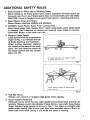
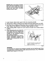
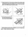
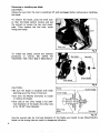
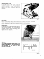
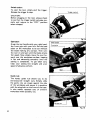
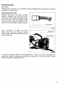
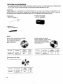
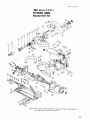
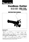
185 mm (744”)
MODEL 5077B
Equlpped wlth Electric Blade Brake
INSTRUCTION MANUAL
DOUBLE
INSULATION
SPEC IFICATIONS
Blade diameter
Max. cutting capacity
No load speed
Overall length
Net weight
185 mm (7-1/4”)
62 mm (2-318”)
4,300 Rimin.
439 mm (17.114”)
6.3 kg (13.9 Ibs)
IMPORTANT SAFETY INSTRUCTIONS
(For All Tools)
WARNING: When using electric tools, basic safety precautions
should always be followed to reduce the risk of fire, electric
shock, and personal injury, including the following:
READALL INSTRUCTIONS.
1. Keep work area clean. Cluttered areas and benches invite injuries.
2. Consider work area environment. Do not use power tools in damp or wet
locations. Keep work area well lit. Do not expose power tools to rain. Do not
use tool in presence of flammable liquids or gases.
3. Keep children away. All visitors should be kept away from work area. Do not
let visitors contact tool or extension cord.
4. Store idle tools. When not in use, tools should be locked-up or stored in a
dry, high place - out of reach of children.
5. Do not force tool. It will do the job better and safer at the rate for which it was
intended.
6. Use correct tool. Do not force small tool or attachment to do the job of a
heavy-duty tool. Do not use tool for purpose not intended; for example, don’t
use circular saw for cutting tree limbs or logs.
7. Dress appropriately. Do not wear loose clothing or jewelry. They can be
caught in moving parts. Rubber gloves and non-skid footwear are
recommendedwhen working outdoors. Wear protective hair covering to
contain long hair.
8. Use safety glasses. Also use face or dust mask if cutting operation is dusty.
9. Do not abuse cord. Never carry tool by cord or yank it to disconnect from
receptacle. Keep cord from heat, oil, and sharp edges.
10. Secure workpiece. Use clamps or a vise to hold work. It is safer than using
your hand; it also leaves both hands free to operate tool.
1 1 . Do not over-reach. Keep proper footing and balance at all times.
12. Maintain tools with care. Keep tools sharp and clean for better and safer
performance. Follow instructions for lubricating and changing accessories.
Inspect tool cords periodically and, if damaged, have repaired by authorized
service facility. Inspect extension cords periodically and replace if damaged.
Keep handles dry, clean, and free from oil and grease.
13. Disconnect tools when not in use, before servicing, and when changing
accessories, such as blades, bits, and cutters.
14. Remove adjusting keys and wrenches. Check to ensure that keys and
adjusting wrenches are removed from tool before turning the tool on.
15. Avoid unintentional starting. Do not carry plugged-in tool with finger on
switch. Be sure switch is OFF when plugging in.
16. Check damaged parts. Before further use of the tool, a guard or other part
that is damaged should be carefully checked to determine that it will operate
properly and perform its intended function. Check for alignment of moving
parts, binding of moving parts, breakage of parts, mounting, and any other
conditions that may affect tool operation. A guard or other part that is damaged
should be properly repaired or replaced by an authorized service center unless
otherwise indicated elsewhere in this instruction manual. Defective switches
should be replaced by an authorized service center. Do not use tool if the
switch does not turn it on and off.
2
17. Extension cords. Make sure your extension cord is in good condition. When
using an extension cord, be sure to use one heavy enough to carry the current
your product will draw. An undersized cord will cause a drop in line voltage
resulting in loss of power and overheating. Table 1 shows the correct size to
use depending on cord length and nameplate ampere rating. If in doubt, use
the next heavier gauge. The smaller the gauge number, the heavier the cord.
Table 1. MINIMUM GAUGE FOR CORD SETS
Total Length of Cord in Feet
0-25
Ampere Rating
More NotMore
Than
Than
I
26-50
1
51-100
1
101-150
I
I
AWG
0
-
6
18
16
16
14
6
-
10
18
16
14
12
12
16
16
14
12
16
14
12
Not recommended
10
I
1
12
18. Outdoor use extension cords. When tool is used outdoors, use only
extension cords intended for outdoor use and so marked.
19. Stay alert. Watch what you are doing. Do not operate tool when you are tired.
20. Guard against electric shock. Prevent body contact with grounded surfaces,
for example: pipes, radiators, ranges, refrigerator enclosures.
21. Replacement parts. When servicing, use only identical replacement part.
22. Polarized plugs: To reduce the risk of electric shock, this equipment has a
polarized plug (one blade is wider than the other). This plug will fit in a
polarized outlet only one way. If the plug does not fit fully in the outlet, reverse
the plug. If it still does not fit, contact a qualified electrician to install the proper
outlet. Do not change the plug in any way.
3
VOLTAGE WARNING: Before connecting the tool to a power source
(receptacle outlet, etc.) be sure the voltage supplied is the same as that
specified on the nameplate of the tool. A power source with voltage greater
than that specified for the tool can result in SERIOUS INJURY to the user, as
well as damage the tool. If in doubt, DO NOT PLUG IN THE TOOL. Using a
power source with voltage less than the nameplate rating is harmful to the
motor.
4
ADDITIONAL SAFETY RULES
1. Keep Guards In Place and I n Working Order.
Never wedge or tie lower guard open. Check operation of lower guard before each use. Don’t use if lower guard does not close briskly over saw blade.
CAUTION: If saw is dropped, lower guard may be bent, restricting full return.
2. Keep Blades Clean and Sharp.
Sharp blades minimize stalling and kickback.
3. DANGER: Keep Hands Away From Cutting Area.
Keep hands away from blades. Don’t reach underneath work while blade
is rotating. Don’t attempt t o remove cut material when blade is moving.
CAUTION: Blades coast after turn off.
4. Support Large Panels.
Large panels must be supported as
shown in Fig. 1 t o minimize the risk
of blade pinching and kickback.
When cutting operation requires
the resting of the saw o n the work
piece, the saw shall be rested on
the larger portion and the smaller
piece cut off.
6+4!k=a
To avoid kickback, do support board
or panel near the cut.
Fig.
Don‘t support board or panel away
from the cut.
Fig. 2
5. Use Rip Fence.
Always use a fence or straight edge guide when ripping.
6. Guard Against Kickback.
Kickback occurs when the saw stalls rapidly and is driven back towards the
operator. Release switch immediately if blade binds or saw stalls. Keep blades
sharp. Support large panels as shown in Fig. 1. Use fence or straight edge
guide when ripping. Don’t force tool. Stay alert exercise control. Don’t remove saw from work during a cut while the blade is moving.
5
NEVER place your hand or fingers
behind the saw. If kickback occurs,
the saw could easily jump backwards over your hand, possibly
causing severe injury.
Fig.
7. Lower Guard. Raise lower guard with the retracting handle.
8. Adjustments. Before cutting be sure depth and bevel adjustments are tight.
9. Use Only Correct Blades In Mounting. Don’t use blades with incorrect size
holes. Never use defective or incorrect blade washers or bolts.
IO. Avoid Cutting Nails. Inspect for and remove all nails from lumber before
cutting.
11. When operating the saw, keep the
cord away from the cutting area
and position it so that it will not be
caught on the workpiece during
the cutting operation.
Operate with proper hand support,
proper workpiece support, and
supply cord routing away from the
work area.
A typical illustration of proper hand
support, workpiece support, and
supply cord routing.
WARNING:
It is important t o support the workpiece properly and t o hold the saw firmly
t o prevent loss of control which could cause personal injury. Fig. 4 illustrates
typical hand support of the saw.
6
12. Place the wider portion of the saw base on that part of the workpiece which
is solidly supported, not on the section that will fall off when the cut is made.
As examples, Fig. 5 illustrates the RIGHT way t o cut off the end of a board,
and Fig. 6 the WRONG way. If the workpiece is short or small, clamp it down.
DON'T TRY TO HOLD SHORT PLECES BY HAND!
Fig.
Fig.
13. Never attempt t o saw w i t h the circular saw held upside down in a
14. Before setting the tool down after completing a cut, be sure that the lower
(telescoping) guard has closed and the blade has come t o a complete stop.
SAVE THESE INSTRUCTIONS.
7
Removing or installing saw blade
CAUTION :
Always b e sure that the tool is switched off and unplugged before removing or installing
the blade.
To remove the blade, press the shaft lock
so that the blade cannot revolve and use
the wrench to loosen the hex bolt clockwise. Then remove the hex bolt, outer
flange and blade.
To install the blade, follow the removal
procedure in reverse. BE SURE TO
TIGHTEN THE HEX BOLT SECURELY.
inner flange
\
Fig. 9
CAUTION :
.Be sure the blade is installed with teeth
pointing up a t the front of the tool.
*Use only the Makita wrenches to install
or remove the blade.
*One side of the inner flange is for 5/8"
hole diameter of the blade; the other side
is for 13/16" hole diameter.
Blade
Outer flange
I
Fig. 1(
Use the correct side for the hole diameter of the blade you intend to use. Mounting the
blade on the wrong side can result in dangerous vibration.
a
Adjusting depth of cut
Loosen the lever on the depth guide and
move the base up or down. At the desired
depth of cut, secure the base by tightening
the lever.
Fig. 1
CAUTION :
Use a shallow depth of cut when cutting thin workpiece for cleaner, safer cuts.
*After adjusting the depth of cut, always tighten the lever securely.
Bevel cutting
Loosen the lever on the bevel scale plate on
the front of the base. Set for the desired
angle (0" -45') by tilting accordingly, then
tighten the lever securely.
Bevel scale plats
Sighting
For straight cuts, align the l e f t notch in the
front of the base with your cutting line on
the workpiece. For 45" bevel cuts, align
the right notch with it.
For straight
cuts
I 1
For 45"
bevel cuts
Base plate
I
Fig. 1
9
Switch action
To start the tool, simply pull the trigger.
Release the trigger to stop.
CAUTION :
Before plugging in the tool, always check
to see that the trigger switch actuates properly and returns to the "OFF" position
when released.
Trigger switch
Operation
Grasp the rear handle with your right hand,
the front grip with your left. Set the base
plate on the workpiece to be cut without
the blade making any contact. Then turn
the tool on and wait until the blade attains
full speed. Now simply move the tool forward over the workpiece surface, keeping
it flat and advancing smoothly until the
sawing i s completed. To get clean cuts,
keep your sawing line straight and your
speed of advance uniform.
Fie. 1!
Guide rule
The handy guide rule allows you to do
extra-accurate straight cuts. Simply slide
the guide rule up snugly against the side
of the workpiece and secure it in position
with the wing bolt on the front of the base.
It also makes repeated cuts of uniform
workpiece width possible, too.
Fig. 1 6
10
MAINTENANCE
CAUTION :
Always be sure that the tool is switched off and unplugged before attempting to perform
inspection or maintenance.
Replacing carbon brushes
Remove and check the carbon brushes
regularly. Replace when they wear down
to the limit mark. Keep the carbon brushes
clean and free to slip in the holders. Both
carbon brushes should be replaced at the
same time. Use only Makita carbon brushes.
I
Limit mark
Fig. 1'
Use a screwdriver to remove the brush
holder caps. Take out the worn carbon
brushes, insert the new ones and secure the
brush holder caps.
Screwdriver
I
1
Fig. 18
To maintain product SAFETY and RELIABILITY, repairs, any other maintenance or
adjustment should be performed by Makita Authorized or Factory Service Centers,
always using Makita replacement parts.
OPTIONAL ACCESSORIES
The accessories listed in this manual are availableat an extra cost from your Makita distributor or Makita factory
service center. Service centers are listed on the warranty card packed with your tool.
CAUTION :
These accessories or attachments are recommended for use with your Makita tool specified in this
manual. The use of any other accessories or attachments might present a risk of injury to persons.
The accessories or attachments should be used only in the proper and intended manner.
0
Guide rule
Part No. 164095-8
0
Wrench 13
Part No. 782016-4
0
Steel carrying case
Part No. 823204-5
Saws
Carbide-tipped saw blade
Faster, smoother, longer sawing
without blade sharpening.
Cuts wood, drywall, plastics,
hard wood, etc.
Chisel tooth combination saw blade
For rip and cross-cut work.
Most frequently used for
general carpentry.
Part No.
792436-4
Hole
diameter
Diameter
I
I
5/8”
I
No.
teeth
20
Combination saw blade
Part No.
792446-1
12
I
diameter
1
7-11 4 (185 mm)
No.
Hole
Diameter
I
I
-
I
518”
teeth
40
Part No.
Diameter
Hole
diameter
No.
teeth
May-26-'87
US
185 mm (7-1/4")
HYPOID SAW
Model 5077B
Note The switch, noise suppressor and other part conftguratlons
may differ from country to country.
13
May-26-'87
MODEL 50778
'iLM
&
DESCRIPTION
1
3
4
5
6
7
8
9
10
11
12
13
14
15
16
17
1s
19
1
1
1
1
1
1
1
1
1
1
3
1
1
1
1
1
1
1
1
20
3
21
1
1
1
22
23
24
25
2
27
1
4
4
28
29
2
2
30
31
33
1
1
1
1
34
2
36
1
1
1
1
4
26
32
37
38
39
40
-
At.,
2
2
Hex Socket Head Bolt M5x14
Flat Washer 5
52
1
1
1
1
1
1
1
1
1
1
53
3
54
55
1
1
56
57
58
59
1
1
1
Side Grip
LWB,
Pan Head Screw M4x10 IWith Washed
Ring Spring 8
Pin 6
compresrlon sprmg 7
Retaining Ring S- 17
Gear Housing
Seal Ring 17
Ball Bearing 6203LLB
Binding Head Screw M5x12
Fan 92
ARMATURE ASSEMBLY
lWith Item 52 & 54 - 571
Insulation Washer
Ball Bearing 608LB
Baffle Plate
Hex Bolt M5x65 lWith Washer]
FIELD ASSEMBLY
Flat Washer 8
Hex Flange Hesd Bolt M8x20
Outer Flange 4 0
Inner Flange 4 0
Spindle
Woodruff Key 4
Bearing Retainer 23-36
Ball Bearing 6003LLB
Retaining Ring 5-42
Safety Cover
Tension Spring 4
Pan Head Screw M5x20 !With Washer]
41
42
43
44
45
46
47
48
49
Bsarlng BOX
Hex Socket Head Bolt M6x12
Rubber Pin 4
~ a iBi e a r l n g w L L e
Retaining Ring S - 1 6
Hypoid Gear36
Sleeve 16
Blade Care
Hex Socket Head Bolt M6x25 !With Warherl
Rubber Sleeve 6
Countersunk Head Screw M6x28
Indication Label
Rivet 0 - 5
Name Plate
Flat Washer 5
Hex Socket Head Bolt M5x30
Brush Holder Cap
Carbon Brush
Motor Housing
Cord
Cord Guard
Strain Relief
Pan Head Screw M4x18 lWith Washer)
Handle Cover
Rubber Pin 4
Switch
Dust cover
Pan Head Screw M4x25 IWRh Washer)
50
51
60
61
62
63
64
65
66
67
68
69
70
71
72
73
74
75
76
77
76
-
2
1
1
1
1
1
1
1
1
1
1
1
1
1
1
1
1
1
1
1
-
Note: The switch and other part specifications may differ from country to country.
14
DESCRIPTION
MACHINE
MACHINE
2
'iLM
Base
wing e m ~ 5 x 1 0
Cap Square Neck Bolt M8x24
Screw M5x12
Flat Washer 8
Flat Washer 8
LeYe, Plate
Lock Plate
Hex Nut MB
Pan Head Screw M4xB IWith Warherl
Spring Pin 6 - 4 5
Hex Bolt M8x28
Lock Plate
Lever Plate
Flat Washer 8
Flat Washer 8
Pan Hesd Screw M4x8 (With Washer)
US
MAKITA LIMITED ONE YEAR WARRANTY
Warranty Policy
Every Makita tool is thoroughly inspected and tested before leaving the factory. It is warranted t o
be free of defects from workmanship and materials for the period of ONE YEAR from the date of
original purchase. Should any trouble develop during this one-year period, retum the COMPLETE
tool, freight prepaid, t o one of Makita’s Factory or Authorized Service Centers. If inspection shows
the trouble is caused by defective workmanship or material, Makita will repair (or at our option,
replace) without charge.
This Warranty does not apply where:
repairs have been made or attempted by others:
repairs are required because of normal wear and tear:
The tool has been abused, misused or improperly maintained;
alterations have been made to the tool.
IN NO EVENT SHALL MAKITA BE LIABLE FOR ANY INDIRECT, INCIDENTAL OR CONSEQUENTIAL DAMAGES FROM THE SALE OR USE O F THE PRODUCT. THIS DISCLAIMER
APPLIES BOTH DURING AND AFTER THE TERM O F THIS WARRANTY.
MAKITA DISCLAIMS LIABILITY FOR ANY IMPLIED WARRANTIES, INCLUDING IMPLIED
WARRANTIES O F “MERCHANTABILITY” AND “FITNESS FOR A SPECIFIC PURPOSE,”
AFTER THE ONE-YEAR TERM O F THIS WARRANTY.
This Warranty gives you specific legal rights, and you may also have other rights which vary from
state to state. Some states d o not allow the exclusion or limitation of incidental or consequential
damages, so the above limitation or exclusion may not apply t o you. Some states d o not allow
limitation on how long an implied warranty lasts, so the above limitation may not apply to you.
c _ _ _
Makita Corporation of America
2650 Gainesville Hwy
Buford, GA 30518
MCA - a195
883588E065
PRINTED IN U.S.A.
1995-9-c