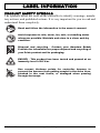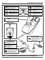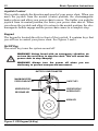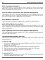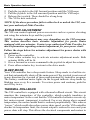
1
BASIC OPERATION INSTRUCTIONS Synergy TRU-Balance VSI Controller TM ACN# 088 609 661 SAFETY GUIDELINES WARNING! An authorized Pride Provider or a qualified technician must perform the initial setup of this product and must perform all of the instructions in this manual. The symbols below are used throughout this owner's manual and on the power chair to identify warnings and important information. It is very important for you to read them and understand them completely. WARNING! Indicates a potentially hazardous condition/ situation. Failure to follow designated procedures can cause either personal injury, component damage, or malfunction. On the product, this icon is represented as a black symbol on a yellow triangle with a black border. MANDATORY! These actions should be performed as specified. Failure to perform mandatory actions can cause personal injury and/or equipment damage. On the product, this icon is represented as a white symbol on a blue dot with a white border. PROHIBITED! These actions are prohibited. These actions should not be performed at any time or in any circumstances. Performing a prohibited action can cause personal injury and/or equipment damage. On the product, this icon is represented as a black symbol with a red circle and a red slash. NOTE: These instructions are compiled from the latest specifications and product information available at the time of publication. We reserve the right to make changes as they become necessary. Any changes to our products may cause slight variations between the illustrations and explanations in this manual and the product you have purchased. The latest/current version of this manual is available on our website. 088 609 661 Copyright © 2009 Pride Mobility Products Corporation INFMANU3383/Rev B/May 2009 VSI Controller www.pridemobility.com TABLE OF CONTENTS LABEL INFORMATION ................................................................... 4 INTRODUCTION ................................................................................ 5 VSI CONTROLLER ............................................................................ 7 PRECAUTIONARY GUIDELINES ............................................... 7 OPERATING THE VSI CONTROLLER .................................... 11 LOCKING/UNLOCKING THE VSI ............................................. 16 ACTUATOR ADJUSTMENT ........................................................ 17 SLEEP MODE ..................................................................................... 17 THERMAL ROLLBACK .................................................................. 17 FAULT CODES .................................................................................. 18 CARE AND MAINTENANCE ........................................................ 19 WARRANTY ....................................................................................... 19 www.pridemobility.com VSI Controller LABEL INFORMATION PRODUCT SAFETY SYMBOLS The symbols below are used on the controller to identify warnings, mandatory actions, and prohibited actions. It is very important for you to read and understand them completely. Read and follow the information in the owner’s manual. Avoid exposure to rain, snow, ice, salt, or standing water whenever possible. Maintain and store in a clean and dry condition. Disposal and recycling - Contact your Quantum Rehab Provider for information on proper disposal and recycling of your Pride product and its packaging. EMI-RFI - This product has been tested and passed at an immunity level of 20 V/m. Use correct tie-down points for controller harness to prevent the harness from getting caught in the drive tires, pinched in the seat frame, or damaged when passing through doorways. VSI Controller www.pridemobility.com Basic Operation Instructions 5 INTRODUCTION WELCOME to Pride Mobility Products Corporation (Pride). The product you have purchased combines state-of-the-art components with safety, comfort, and styling in mind. We are confident that the design features will provide you with the conveniences you expect during your daily activities. Understanding how to safely operate and care for this product should bring you years of trouble free operations and service. Read and follow all instructions, warnings, and notes in this manual before attempting to operate your product for the first time. You must also read all instructions, warnings, and notes contained in any supplemental instructional booklets for the controller, front riggings, and/or seating system that accompanied your power chair before initial operation. Your safety depends upon you, as well as your provider, caretaker, or healthcare professional in using good judgement. This manual is to be used in addition to the power base owner’s manual that came with your power chair. If there is any information in this manual which you do not understand, or if you require additional assistance for setup or operation, please contact your authorized Pride Provider. Failure to follow the instructions, warnings, and notes in this manual and those located on your Pride product can result in personal injury and/or product damage and will void Pride’s product warranty. PURCHASER’S AGREEMENT By accepting delivery of this product, you promise that you will not change, alter, or modify this product or remove or render inoperable or unsafe any guards, shields, or other safety features of this product; fail, refuse, or neglect to install any retrofit kits from time to time provided by Pride to enhance or preserve the safe use of this product. INFORMATION EXCHANGE We want to hear your questions, comments, and suggestions about this manual. We would also like to hear about the safety and reliability of your new Pride product, and about the service you received from your authorized Pride Provider. www.pridemobility.com VSI Controller 6 Basic Operation Instructions Please notify us of any change of address, so we can keep you apprised of important information about safety, new products, and new options that can increase your ability to use and enjoy your Pride product. NOTE: If you ever lose or misplace your product registration card or your copy of this manual, contact us and we will be glad to send you a new one immediately. My authorized Pride Provider Is: Name: ______________________________________________________ Address: ____________________________________________________ Phone Number:_______________________________________________ Purchase Date: _______________________________________________ VSI Controller www.pridemobility.com Basic Operation Instructions 7 VSI CONTROLLER The VSI Controller is a fully-programmable, integral electronic controller system that allows you to operate your power chair. It is designed to allow the user to have complete control over chair movement and speed. The controller has been pre-programmed to meet a typical user’s needs. The program is set using either a personal computer with software provided by the controller manufacturer or with a hand-held programmer, also provided by the controller manufacturer. WARNING! The controller program can affect speed, acceleration, deceleration, dynamic stability, and braking. If it is programmed incorrectly or outside of the safe limits as determined by your healthcare professional, it can create a dangerous situation. Only the power chair manufacturer, an authorized representative of the manufacturer, or a trained service technician should program the controller. PRECAUTIONARY GUIDELINES Before operating the VSI Controller, please read the following. These guidelines are provided for your benefit and will aid you in the safe operation of the controller system. Turn off the power to the controller when transferring to or from your power chair. Follow all of the procedures and heed the warnings as explained in your power chair owner’s manual. www.pridemobility.com VSI Controller 8 Basic Operation Instructions Electromagnetic and Radio Frequency Interference (EMI/RFI) WARNING! Laboratory tests have shown that electromagnetic and radio frequency waves can have an adverse affect on the performance of electrically-powered mobility vehicles. Electromagnetic and Radio Frequency Interference can come from sources such as cellular phones, mobile two-way radios (such as walkie-talkies), radio stations, TV stations, amateur radio (HAM) transmitters, wireless computer links, microwave signals, paging transmitters, and medium-range mobile transceivers used by emergency vehicles. In some cases, these waves can cause unintended movement or damage to the control system. Every electrically-powered mobility vehicle has an immunity (or resistance) to EMI. The higher the immunity level, the greater the protection against EMI. This product has been tested and has passed at an immunity level of 20 V/m. WARNING! Be aware that cell phones, two-way radios, laptops, and other types of radio transmitters may cause unintended movement of your electrically-powered mobility vehicle due to EMI. Exercise caution when using any of these items while operating your mobility vehicle and avoid coming into close proximity of radio and TV stations. WARNING! The addition of accessories or components to the electrically-powered mobility vehicle can increase the susceptibility of the vehicle to EMI. Do not modify your power chair in any way not authorized by Pride. WARNING! The electrically-powered mobility vehicle itself can disturb the performance of other electrical devices located nearby, such as alarm systems. NOTE: For further information on EMI/RFI, go to the Resource Center on www.pridemobility.com. If unintended motion or brake release occurs, turn your controller off as soon as it is safe to do so. Contact Pride or your authorized Pride Provider to report the incident. VSI Controller www.pridemobility.com Basic Operation Instructions 9 VSI Controller Features Figure 1 provides information on the VSI components and connections. Use this diagram to familiarize yourself with the function and location of each component before using the VSI Controller. The following functions are available with the VSI Controller: Joystick Control The joystick is used to control the direction and speed of the power chair. Actuator Adjustment The user can control positioning of power accessory actuators with the VSI. Drive Profile Selection The user can select from available drive profiles, if programmed. Speed Adjustment The user can increase or decrease the maximum speed of the power chair, if programmed. Sleep Mode This feature is designed to preserve battery charge, and can be disabled through programming. Thermal Rollback This is a safety feature designed to prevent the power chair from overheating and causing damage to the motors or controller. Light Controls The user can control the lights on the power chair. www.pridemobility.com VSI Controller 10 Basic Operation Instructions Battery Condition Meter On/Off Key A series of ten LEDs, which indicate charge level. Press to power on or off the power chair and controller. Speed/Profile Indicator A series of five LEDs, which display the speed/profile setting. Horn Key Activates a warning horn. Speed/Profile Decrease Speed/Profile Increase Used to decrease the speed/ profile setting. Used to increase the speed/ profile setting. Joystick Controls the speed and direction of the power chair. FRONT VIEW 3-Pin OBC Connector Provides battery charging voltage (onboard chargers only) to the controller and provides the charger inhibit signal. 3-Pin Off-board Charger/ Programming Socket Connects to battery charger plug or programmer. Ferrite Core Reduces electromagnetic emissions. 9-Pin Beau Connector Harness Main power cable which accepts battery voltage and sends motor signals to the power chair. Figure 1. VSI Components and Connections (9-Pin Configuration) VSI Controller www.pridemobility.com Basic Operation Instructions OPERATING CONTROLLER THE 11 VSI The VSI Controller is used to operate your power chair and all of its components. See figures 2, 3, and 4. The VSI controller may consist of: 1. joystick 2. keypad 3. 3-pin off-board charger/programming socket Figure 2. VSI Controller (9-pin) 4. 3-pin onboard charger (OBC) connector 5. 9-pin controller connector 6. 6-pin actuator connector (for optional equipment) 7. 2-pin battery connector 8. 4-pin motor/brake connectors (left and right) 9. 3-pin lighting connector (for optional equipment) 10. lighting module Figure 3. VSI Controller (Battery and Motor/Brake Connectors) Figure 4. VSI Controller (Lighting Module) www.pridemobility.com VSI Controller 12 Basic Operation Instructions Joystick Control The joystick controls the direction and speed of your power chair. When you move the joystick from the neutral (center) position, the electromagnetic brakes release and allow your power chair to move. The farther you push the joystick from its neutral position, the faster your power chair moves. When you release the joystick and allow it to return to the neutral position, the electromagnetic brakes engage and the power chair comes to a complete stop. Keypad The keypad is located directly in front of the joystick. It contains keys that you will use to control your power chair. See figures 5 and 6. On/Off Key The on/off key turns the system on and off. WARNING! Unless faced with an emergency situation, do not use the on/off key to stop the chair. This will cause the power chair to stop abruptly. WARNING! Always turn the power off when you are stationary to prevent unexpected movement. BATTERY CONDITION METER MAXIMUM SPEED/ PROFILE INDICATOR ON/OFF KEY SPEED/PROFILE DECREASE KEY SPEED/PROFILE INCREASE KEY HORN KEY Figure 5. VSI Keypad (4-Key) VSI Controller www.pridemobility.com Basic Operation Instructions 13 BATTERY CONDITION METER MAXIMUM SPEED/ PROFILE INDICATOR ON/OFF KEY *ACTUATOR LIGHT *ACTUATOR LIGHT *ACTUATOR KEY *ACTUATOR KEY SPEED/PROFILE INCREASE KEY SPEED/PROFILE DECREASE KEY HORN KEY * For optional equipment on some models. Figure 6. VSI Keypad (6-Key) MAXIMUM SPEED/ PROFILE INDICATOR BATTERY CONDITION METER ON/OFF KEY HAZARD LIGHTS LIGHT KEY LEFT TURN SIGNAL RIGHT TURN SIGNAL HORN KEY ACTUATOR KEY SPEED/PROFILE DECREASE KEY SPEED/PROFILE INCREASE KEY Figure 7. VSI Keypad (9-Key) www.pridemobility.com VSI Controller 14 Basic Operation Instructions Battery Condition Meter The battery condition meter is located in front of the joystick. This is a 10segment illuminated display that indicates that the VSI is powered on and also gives the battery status, the VSI status, and the electrical system status. Red, yellow, and green lights lit: Batteries charged; VSI and electrical system OK. Red and yellow lights lit: Charge batteries if possible; VSI and electrical system OK. Red lights only lit or slow flash: Charge batteries as soon as possible; VSI and electrical system OK. Rapid flash of lights: The VSI has detected a problem in the electrical system and power chair drive operation is inhibited. Refer to “Fault Codes.” Ripple side to side of lights twice followed by seven flashing lights: The joystick was not in the neutral position when the controller was turned on. Refer to “Fault Codes.” Ripple side to side of lights: The VSI has detected an off-board charger plugged into the off-board charger port. Refer to “Fault Codes.” NOTE: If you have attempted to resolve the problem and still get “ripple side to side of lights,” contact an authorized Pride Provider. NOTE: When the batteries approach a discharged state, the red lights will begin to slowly flash, reminding you the batteries need to be charged immediately! Speed/Profile Keys There are two keys that control either speed or profiles, depending on your VSI program. Press the speed/profile increase key to increase the speed or change the profile. Press the speed/profile decrease key to decrease the speed or change the profile. The speed/profile setting is displayed on the maximum speed/profile indicator. If your power chair was programmed with a drive profile, contact your authorized Pride Provider for more information. NOTE: We recommend that the first few times you operate your power chair, you set the speed to the slowest setting until you become familiar with your new power chair. VSI Controller www.pridemobility.com Basic Operation Instructions 15 Actuator Keys and Actuator Lights (for optional equipment) Actuator keys and actuator lights are used for optional equipment such as power elevating seats or power elevating leg rests. For specific operation of the actuator keys and actuator lights, refer to “Actuator Adjustment.” Horn Key The horn key activates a warning horn. 3-Pin Off-board Charger/Programming Socket You may use an off-board charger to charge your power chair batteries through the 3-pin socket located on the front of the VSI. See figure 8. If you use an off-board charger, the charger current should not exceed 8 amps. Contact your authorized Pride Provider for more information. Figure 8. 3-pin Off-Board Charger Socket WARNING! Only chargers with Neutrik NC3MX plugs should be connected to the off-board charger/programming socket. See your authorized Pride Provider for more information. NOTE: The socket may also be used for reprogramming the VSI. Contact an authorized Pride Provider for more information. 3-Pin Onboard Charger (OBC) Connector This connects the VSI to the onboard battery charger. This connection provides an inhibit that disables the VSI when the onboard battery charger is on. The 3-pin OBC connector is coded with colored dots. The dots are positioned so that you align the flat side of the male connector with the flat side of the female connector before making the connection. It is typically mounted next to the controller connector on the power base. Refer to your power chair owner’s manual for exact location. WARNING! Failure to properly align the connectors can result in damage to the VSI, the charger harness, and the connectors. www.pridemobility.com VSI Controller 16 Basic Operation Instructions 9-Pin Controller Connector This connects the VSI to the power chair’s batteries, motors, and motor brakes. It is typically mounted on the power base. Refer to your power chair owner’s manual for exact location. 6-Pin Actuator Connector (For Optional Equipment) This connects the VSI to optional equipment such as a lighting system or a power elevating seat. It is typically mounted on the power base. Refer to your power chair owner’s manual for exact location. 2-Pin Battery Connector The 2-pin battery connector connects the controller to both batteries. 4-Pin Motor/Brake Connectors The 4-pin motor/brake connectors connect each motor and brake to the controller. There are two motor/brake connectors, one each for the left and right motors and brakes. 3-Pin Lighting Connector (For Optional Equipment) The 3-pin lighting connector connects the VSI to a separate lighting module located on the power base. LOCKING/UNLOCKING THE VSI The VSI has a feature that enables you to lock your power chair to prevent unauthorized use. To lock the VSI: 1. With the VSI powered on, press and hold the on/off key. After one (1) second, the VSI should beep. 2. Release the on/off key. 3. Push the joystick to the full forward position until the VSI beeps. 4. Pull the joystick to the full rearward position until the VSI beeps. 5. Release the joystick. There should be a long beep. 6. The VSI is now locked. To unlock the VSI: 1. Press the on/off key and power on the VSI. The maximum speed/profile indicator should ripple side to side. VSI Controller www.pridemobility.com Basic Operation Instructions 2. 3. 4. 5. 17 Push the joystick to the full forward position until the VSI beeps. Pull the joystick to the full rearward position until the VSI beeps. Release the joystick. There should be a long beep. The VSI is now unlocked. NOTE: If the above procedure fails to either lock or unlock the VSI, contact your authorized Pride Provider. ACTUATOR ADJUSTMENT The VSI can control optional power accessories such as a power elevating seat using the actuator keys and the joystick. NOTE: Actuator adjustment may vary depending on the VSI program. This section describes basic actuator adjustment for power chairs equipped with one actuator. Contact your authorized Pride Provider for more information regarding actuator adjustment for your power chair. Follow the steps below for actuator adjustment for power chairs with one actuator: 1. Power on the controller. 2. Press either actuator key to activate actuator adjustment mode. Both actuator LEDs will be lit. 3. Give a forward or reverse command to the joystick to adjust the actuator. 4. Press either actuator key to return to the drive mode. SLEEP MODE Your VSI controller has a sleep mode feature. Sleep mode is a built-in circuit that automatically shuts off the main power if the joystick is not moved in any direction for a period of time predetermined by controller program. The battery condition meter lights on the keypad indicate sleep mode by blinking once every five seconds. To restore power and continue, push the on/off key twice. THERMAL ROLLBACK The VSI controller is equipped with a thermal rollback circuit. This circuit monitors the temperature of the controller, which roughly translates to motor temperature. In the event that the VSI controller becomes excessively hot, motor current (amperage) is reduced. For every degree above normal temperature, the motor current limit is reduced proprotionally. This reduces “power,” which could also reduce power chair speed. nce the VSI controller reaches its temperature limit, the current output is reduced to zero and your power chair will stop. This allows the electrical components and motors to www.pridemobility.com VSI Controller 18 Basic Operation Instructions cool down. When the temperature returns to a safe level, your power chair resumes its normal operation. FAULT CODES The VSI controller is designed with the user’s safety as the prime consideration. It incorporates many sophisticated self-test features which search for potential problems at a rate of 100 times per second. If the VSI detects a problem either in its own circuits or in the power chair’s electrical system, it may decide to stop the power chair, depending on the severity of the problem. The VSI is designed to maximize the user’s safety under all normal conditions. The table below identifies the individual fault codes. Fault codes are displayed as a rapid flashing of the lights. If you encounter one of these fault codes or experience any other problems with your power chair, contact an authorized Pride Provider. Flashing Lights Diagnosis and Solution 1 The batteries need charging or there is a bad connection to the batteries. Check the connections to the batteries. If the connections are good, try charging the batteries. 2 The left motor has a bad connection. Check the left motor connection. 3 The left motor has a short circuit to another connection. Contact your authorized Pride Provider. 4 The right motor has a bad connection. Check right motor connection. 5 The right motor has a short circuit to another connection. Contact your authorized Pride Provider. Ripple side to The power chair is being inhibited by the off-board battery charger. side of lights 7 8 A joystick fault is indicated. Make sure that the joystick is in the (center) position before turning on the controller. A controller system fault is indicated. Make sure that all connections are secure and the batteries are fully charged. 9 The parking brakes have a bad connection. Check the parking brake motor connections. Make sure the controller connections are secure. 10 An excessive voltage has been applied to the controller. This is usually caused by a poor battery connection. Check the battery connections. VSI Controller www.pridemobility.com Basic Operation Instructions 19 CARE AND MAINTENANCE Refer to your power chair owner’s manual for proper cleaning and disposal instructions. WARRANTY For two (2) years from the date of purchase, Pride will repair or replace at our option to the original purchaser, free of charge, the controller or any of its components found upon examination by an authorized representative of Pride to be defective in material and/or workmanship. www.pridemobility.com VSI Controller Pride Mobility Products Corporation 182 Susquehanna Avenue Exeter, PA 18643-2694 USA Pride Mobility Products Company 380 Vansickle Road Unit 350 St. Catharines, Ontario L2R 6P7 Canada Pride Mobility Products Ltd. 32 Wedgwood Road Bicester, Oxon OX26 4UL Pride Mobility Products Australia Pty. Ltd. 21 Healey Road Dandenong, 3175 Victoria, Australia Pride Mobility Products Italia S.r.l. Via del Progresso - ang. Via del Lavoro Loc. Prato della Corte 00065-Fiano Romano (RM) Pride Mobility Products Europe B.V. Castricummer Werf 26 1901 RW Castricum The Netherlands *INFMANU3383*