1
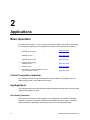
APOGEE Unit Vent
Controller ⎯
0 to 10V Output
Owner’s Manual
125-1957
Rev. CA, July 2007
Siemens Building Technologies, Inc.
Rev. CA, July 2007
NOTICE
The information contained within this document is subject to change without notice and should not be construed as a
commitment by Siemens Building Technologies, Inc. Siemens Building Technologies, Inc. assumes no responsibility
for any errors that may appear in this document.
All software described in this document is furnished under a license and may be used or copied only in accordance
with the terms of such license.
WARNING
This equipment generates, uses, and can radiate radio frequency energy and if not installed and used in accordance
with the instructions manual, may cause interference to radio communications. It has been tested and found to
comply with the limits for a Class A digital device, pursuant to Part 15 of the FCC rules. These limits are designed to
provide reasonable protection against such interference when operated in a commercial environment. Operation of
this equipment in a residential area is likely to cause interference in which case users at their own expense will be
required to take whatever measures may be required to correct the interference.
SERVICE STATEMENT
Control devices are combined to make a system. Each control device is mechanical in nature and all mechanical
components must be regularly serviced to optimize their operation. All Siemens Building Technologies branch offices
and authorized distributors offer Technical Support Programs that will ensure your continuous, trouble-free system
performance.
For further information, contact your nearest Siemens Building Technologies, Inc. representative.
Copyright 2006 by Siemens Building Technologies, Inc.
TO THE READER
Your feedback is important to us. If you have comments about this manual, please submit them to
SBT_technical.editor.us.sbt@siemens.com
CREDITS
APOGEE is a registered trademark of Siemens Building Technologies, Inc.
Insight for Minicomputers is a registered trademark of Siemens Building Technologies, Inc.
Insight for Personal Computers is a registered trademark of Siemens Building Technologies, Inc.
Country of Origin: US
Table of Contents
How To Use This Manual................................................................................................. iv
Manual Organization ......................................................................................................iv
Manual Conventions ................................................................................................... v
Manual Symbols .......................................................................................................... v
Datamate Software ..................................................................................................... v
Getting Help ................................................................................................................vi
Where To Send Comments.........................................................................................vi
Product Overview ............................................................................................................. 1
Introduction .................................................................................................................... 1
Ordering Notes ............................................................................................................ 1
Hardware Inputs .......................................................................................................... 2
Hardware Outputs ....................................................................................................... 3
Controller LED Indicators ............................................................................................ 4
Temperature Sensors ................................................................................................. 4
Actuators ..................................................................................................................... 5
Applications....................................................................................................................... 6
Basic Operation ............................................................................................................. 6
Control Temperature Setpoints ................................................................................... 6
Day/Night Mode........................................................................................................... 6
Valve Configuration ..................................................................................................... 7
Heating and Cooling Switchover ................................................................................. 7
Control Loops .............................................................................................................. 7
Morning Warm-up/Cool-down ..................................................................................... 8
ON/OFF Coil Valve Control ......................................................................................... 8
Electric Heat ................................................................................................................ 8
Fan Operation ............................................................................................................. 8
Fail-safe Operation ...................................................................................................... 8
Application 2281 – Heating and/or Chilled Water Cooling, ASHRAE Cycles I and II . 10
Application 2283 – Heating and/or Chilled Water Cooling, ASHRAE Cycle III .......... 13
Application 2284 – Heating and DX Cooling, ASHRAE Cycles I and II ..................... 16
Application 2286 - Heating and DX Cooling, ASHRAE Cycle III ................................. 18
Application 2287 – Heating and Cooling, Nesbitt Cycle W......................................... 20
Overview ................................................................................................................... 20
Application 2299 – Slave Mode ................................................................................... 22
Overview ................................................................................................................... 22
I
APOGEE Unit Vent Controller⎯0 to 10V Output Owner’s Manual
Point Database ................................................................................................................ 23
Troubleshooting .............................................................................................................. 33
Overview ...................................................................................................................... 33
Basic Service Information ......................................................................................... 33
Ordering Replacement Parts..................................................................................... 34
Preventive Maintenance............................................................................................ 34
Safety Features ......................................................................................................... 34
Controller LEDs ......................................................................................................... 34
Glossary ........................................................................................................................... 35
Overview ...................................................................................................................... 35
ii
Table of Contents
iii
How To Use This Manual
This manual is written for the owner and user of the Siemens Building Technologies, Inc. Unit
Vent Controller – 0 to 10V, often referred to as controller for the remainder of this manual.
This manual is designed to help you become familiar with the controller and its applications.
This chapter covers manual organization, manual symbols and conventions used and how to
access help.
Manual Organization
This manual contains the following chapters:
•
Chapter 1 Product Overview, describes the hardware components and accessories
used with the controller.
•
Chapter 2 Applications, describes the control applications available in the controller.
•
Chapter 3 Point Database, defines the point database descriptors and includes
addresses and applications.
•
Chapter 4 Troubleshooting, describes basic corrective measures to take should you
encounter a problem when using this controller. For issues not covered in this
chapter, contact your local Siemens Building Technologies representative.
•
A Glossary describes the terms and acronyms used in this manual.
•
An Index is provided to assist you in finding information.
Siemens Building Technologies,Inc.
iv
Manual Organization
Manual Conventions
The following table lists conventions used in this manual.
Convention
Actions that you should
perform are specified in
boldface font.
Example
Type F for Field panels.
Click OK to save changes and close the dialog box.
Error and system
messages are displayed
in Courier New font.
The message Report Definition successfully renamed
appears in the status bar.
New terms appearing for
the first time are
italicized.
The Open Processor continuously executes a user-defined set of
instructions called the control program.
Manual Symbols
The following table lists symbols that used to draw your attention to important information.
Notation
Symbol
Meaning
CAUTION:
Indicates that equipment damage or loss of data may
occur, if a procedure is not performed as specified.
WARNING:
Indicates that personal injury or loss of life may occur to the
user, if a procedure is not performed as specified.
Datamate Software
Datamate is a customer software tool for all controller communications. There are two
versions: Datamate Base, and Datamate Advanced. Datamate Base works on an IBMcompatible Personal Computer (PC), or a Handheld PC or Pocket PC™ running Windows
CE. Datamate Advanced works only on an IBM-compatible Personal Computer.
With Datamate, you can back up, restore and edit any APOGEE® database (but only
Datamate Advanced allows you to edit points offline). Backing up and restoring a database is
accomplished while connected to any APOGEE® field panel, or to the Automation Level
Network (ALN) or Field Level Network (FLN) device in question. A modem and telephone
lines can also be used. Databases can be saved for permanent storage or used as backup.
For more information on Datamate software, refer to the appropriate user guide for the
version of Datamate you are using (Base or Advanced), or contact your local Siemens
Building Technologies, Inc. representative.
Siemens Building Technologies,
v
APOGEE Unit Vent Controller⎯0 to 10 V Output Owner’s Manual
Getting Help
For more information about the Unit Vent Controller, contact your local Siemens Building
Technologies representative.
Where To Send Comments
Your feedback is important to us. If you have comments about this manual, please submit
them to SBT_technical.editor.us.sbt@siemens.com
vi
Siemens Building Technologies. Inc.
1
Product Overview
Introduction
The Unit Vent Controller—0 to 10V Output is the Siemens Building Technologies, Inc.
Terminal Equipment Controller (TEC) used in unit ventilator applications. See Figure 1. It
provides Direct Digital Control (DDC) for five applications. The controller can operate as an
independent, stand-alone, DDC room controller or be networked with an APOGEE field
panel.
The controller provides all termination, input/output, system and local communication
connections. See Figure 1. The controller hardware consists of the controller with cover and
mounting bracket.
Table 1. Unit Vent Controller – 0 to 10 V Output Applications.
Standard Applications
2281 Heating and/or Chilled Water Cooling, ASHRAE Cycles l and II
2283 Heating and/or Chilled Water Cooling, ASHRAE Cycle III
2284 Heating and DX Cooling, ASHRAE Cycles I and II
2286 Heating and DX Cooling, ASHRAE Cycle III
2287 Nesbitt Cycle W
2299Slave Mode (no control; available for set up, and point extension device)
Ordering Notes
Unit Vent Controller – 0 to 10 Volt Output
Siemens Building Technologies, Inc.
540-509
1
APOGEE Unit Vent Controller⎯0 to 10V Output Owner’s Manual
COVER
CONTROLLER
BOARD
MOUNTING
HOLE
(2)
24 V-AC
TEC0197R3
C
H
C H
DO 1 DO 2 DO 3 DO 4 DO 5 DO 6 DO 7 DO 8 DI 3
NO C NO C NO C NO C NO C NO C NO C NO C AI 3
DI 2
DI 4
LAN
TRUNK
AO 1 AO 2 AO 3
+ - + - + -
1 2 3 4 5 6 7 8 9 10 11 12 13 14 15 16 17 18 19 20 21 22 23 24 25 26 27 28
1 2 3 4 5 6 7 8 9 10 11 12 13 14 15 16 17 18 19 20 21 22 23 24 25 26 27 28
TX RX
+
- S
+
-
BST
MOUNTING
RAIL
RTS
S
DO LEDS
POWER
TRUNK
TERMINATIONS
INPUT / OUTPUT TERMINATIONS
TRANSMIT LED
LAN
TRUNK
TERMINATIONS
ROOM TEMPERATURE
SENSOR / MMI PORT
BST LED
RECEIVE LED
Figure 1. Unit Vent Controller - 0 to 10V Output.
Hardware Inputs
Analog
•
Averaging air temperature sensor
•
Room temperature sensor
•
Room temperature setpoint dial (optional)
•
Low Temperature Detection Thermostat (LTDT)
•
Night mode override (optional)
•
Wall switch (optional)
Digital
2
Siemens Building Technologies, Inc.
Introduction
Hardware Outputs
Analog (0 to 10V)
Application
•
Cooling valve actuator
2281, 2283, 2287
•
Face-bypass damper actuator
2281, 2283, 2284, 2286
•
Heating valve actuator
2281, 2283, 2284, 2286, 2287
•
Outdoor air damper actuator
2281, 2283, 2284, 2286
Application
Digital
•
Auxiliary radiation electric coil contact; or,
auxiliary radiation two-position valve actuator
2281, 2283, 2284, 2286
•
Unit fan
2281, 2283, 2284, 2286, 2287
•
First stage electric heat
2281, 2283, 2284, 2286
•
Second stage electric heat
2281, 2283, 2284, 2286
•
Third stage electric heat
2281, 2283, 2284, 2286
•
Two-position cooling valve actuator
2281, 2283, 2284, 2286
•
Two-position heating valve actuator
2281, 2283, 2284, 2286
•
DX coil
2284, 2286, 2287
Power Wiring
The controller is powered by 24 Vac and connects to the two screw terminals on the
controller. Labeled “C” (Common) and “H” (Hot) on the terminal block labeled “24 VAC”. No
earth-ground connection is required (Figure 2).
Communication Wiring
The controller connects to the field panel by means of a Floor Level Network (FLN) trunk.
Communication wiring connects to the three screw terminals on the controller labeled “+”
(positive), “-“ (negative), and “S” (Shield) (Figure 3).
Siemens Building Technologies, Inc.
3
APOGEE Unit Vent Controller⎯0 to 10V Output Owner’s Manual
FLN TRUNK
24 V-AC
E
C H
DO 1 DO 2 DO 3 DO 4 DO 5
NO C NO C NO C NO C NO C NO
+ - S
1 2 3 4 5 6 7 8 9 10 11 1
1 2 3 4 5 6 7 8 9 10 11 12
(SHIELD)
TEC0470R1
COMMON
TEC0253R2
24 VAC HOT
CONTROLLER POWER WIRING
(SHIELD)
(-)
(+)
(-)
(+)
NOTE: NO EARTH GROUND CONNECTION
Figure 2. Power Wiring.
Figure 3. Communication Wiring.
Controller LED Indicators
The controller has eleven Light Emitting Diode (LED) indicators. See Figure 1. Table 2 lists
the type, the abbreviation on the controller, and the indication of each LED.
Table 2. Controller LEDS.
LED Type
Label
(if present)*
LED
Number
Indication
DO
LED 1 to
LED 8
1 to 8
Receive
RX
9
Indicates, when flashing, that the controller is
receiving information from the field panel.
Transmit
TX
10
Indicates, when flashing, that the controller is
transmitting information to the field panel.
Basic Sanity Test
BST
11
Indicates, when flashing ON and OFF once
per second, that the controller is functioning
property.
Indicates the ON/OFF status of the
DO associated with it. A glowing LED
indicates that the DO is energized.
*Some LED labels and numerals may be hidden by the controller cover.
Temperature Sensors
Temperature sensors used with the Unit Vent Controller—0 to 10V Output include an
electronic room, mixed air or discharge air temperature sensor.
Room Temperature Sensor
The Terminal Equipment Controller room temperature sensor connects to the controller by
means of a cable pre-terminated at both ends with a 6-conductor RJ-11 plug-in connector.
See Figure 1 for the location of the room temperature sensor/Man-Machine Interface (MMI)
port.
4
Siemens Building Technologies, Inc.
Introduction
Mixed Air/Discharge Air Temperature Sensor
The mixed air/discharge air temperature sensor is a 100K ohm thermistor that connects to
the controller at the screw terminals for Al 3.
For more information about Siemens Building Technologies, Inc. temperature sensors,
contact your local Siemens Building Technologies, Inc. representative.
Actuators
Damper Actuators
The damper actuator used with the Unit Vent Controller—0 to 10V Output is a 0 to 10V spring
return electronic damper motor that positions an outside air damper. A 0 to 10V electronic
damper motor can be used to position a face-and-bypass damper.
Valve Actuators
The valve actuators used with the Unit Vent Controller—0 to 10V Output are modulating
spring return and non-spring return electronic valve motors that position the valves.
Related Equipment
•
Relay Module
•
Damper Actuator(s)
•
Valve Actuator(s)
•
Mixed Air/Discharge Air Temperature Sensor (optional)
•
TEC Room Temperature Sensor
Contact your local Siemens Building Technologies, Inc. representative for product numbers
and more information.
Siemens Building Technologies, Inc.
5
2
Applications
Basic Operation
The Unit Vent Controller⎯0 to 10V Output provides Direct Digital Control (DDC) technology
for unit ventilator applications. The applications available in this controller are as follows:
•
Heating and/or Chilled Water Cooling,
ASHRAE Cycles l and II
Application 2281
Heating and/or Chilled Water Cooling,
ASHRAE Cycle III
Application 2283
Heating and DX Cooling,
ASHRAE Cycles I and II
Application 2284
Heating and DX Cooling,
ASHRAE Cycle III
Application 2286
•
Nesbitt Cycle W
Application 2287
•
Slave Mode (no control; available for set up,
and point extension device)
Application 2299
•
•
•
Control Temperature Setpoints
The controller maintains a specified temperature setpoint based on Day/Night mode, the
heating/cooling mode, or the setpoint dial (if used).
Day/Night Mode
The controller maintains the specified day setpoint temperature during daytime hours and the
specified night setpoint at night.
Day Heating Operation
The controller maintains the room temperature by resetting the unit ventilator's discharge
temperature setpoint (2281/2284), modulating the available coil control device, controlling
auxiliary radiation (if provided), positioning the outdoor air or face-bypass damper.
6
Siemens Building Technologies,Inc.
Basic Operation
Day Cooling Operation
The controller maintains the room temperature by resetting the unit ventilator's discharge
temperature setpoint (2281), running the face-bypass damper at full all the time, modulating
or cycling the available coil control device (DX coil – 2284) or positioning the outdoor air
damper.
Night Heating Operation
The controller maintains the room temperature turning the fan and heating on and off as
required.
Night Cooling Operation
The controller maintains the room temperature by turning the fan and cooling on and off as
required.
Night Mode Override Switch
If the RTS has an override switch, it can be used to command the controller into day mode
for an adjustable amount of time. This only affects a controller in night mode.
Valve Configuration
2-Pipe Heating/Cooling – units with one valve, controlling a coil that may have hot water or
chilled water (depending on the season).
4-Pipe Heating or Cooling – units that are heating or cooling only, units with a heating and a
cooling coil, units with electric heating, etc.
Heating and Cooling Switchover
NOTE:
For 2-pipe heating/cooling (Application 2281 and 2283), a field panel must
control the switchover between heating and cooling.
The heating/cooling switchover determines whether the controller is in heating or cooling
mode by monitoring the room temperature and the demand for heating and cooling (as
determined by the temperature control loops).
Control Loops
Room Loop – uses the control setpoint and room temperature to set the discharge setpoint
between the minimum and maximum discharge temperature (2281, 2284).
Heating Loop – maintains room temperature setpoint by turning valves and/or electric heat
stages on and off.
Siemens Building Technologies, Inc.
7
APOGEE Unit Vent Controller⎯0 to 10 V Output Owner’s Manual
Cooling Loop – maintains room temperature setpoint by turning valves on and off and using
free cooling (mixed air control) when available.
Auxiliary Loop – modulates the auxiliary loop using the auxiliary setpoint and discharge
setpoint (2284).
Mixed Air Loop – modulates the mixed air loop using the mixed air setpoint and mixed air
temperature (2283).
DX Loop – modulates the cooling loop using the control setpoint and room temperature
(2284).
Morning Warm-up/Cool-down
Morning warm-up or cool-down occurs after the controller switches from night mode to day
mode, upon power-up, or if the controller is reset. During morning warm-up or cool-down, the
controller provides maximum heating or cooling with the outdoor air damper closed until the
temperature of the space reaches setpoint.
ON/OFF Coil Valve Control
When a face-bypass configuration is used, the coils may be turned on and off with twoposition valves using DOs.
Electric Heat
If electric heat is used, it is controlled as follows:
HTG OUTPUT
(Point 60)
Stage 1
Stage 2
Stage 3
0% to 33%
ON
OFF
OFF
34% to 66%
ON
ON
OFF
67% to 100%
ON
ON
ON
In addition, no stage may turn on or off until the time delay has elapsed. Stage one will
always be the first stage to turn on and the last stage to turn off.
Fan Operation
Day Mode – The fan is on all the time.
Night Mode – The fan only operates when required for heating or cooling.
Fail-safe Operation
A low temperature detection thermostat (LTDT) can be used to signal the controller when the
temperature drops below the low temperature limit.
8
Siemens Building Technologies. Inc.
Basic Operation
If the room temperature sensor input to the Unit Vent Controller fails or the LTDT equals ON,
the controller goes through the following shutdown sequence:
•
Outdoor air damper is closed.
•
Heating is full ON (except electric, which is OFF).
•
Cooling is full OFF.
•
Face-bypass damper is open to face.
•
Fan is OFF.
•
Auxiliary radiation is OFF.
•
Two-position heating valve actuator is open.
•
Two -position cooling valve actuator is closed.
NOTE:
DO 2 is not commanded by the fail-safe mode; all other DOs can be affected.
If the discharge air temperature sensor fails, the following conditions occur:
•
If the last valid value is greater than 150 degrees, the heat is turned off, the outdoor
air damper is closed and the fan is turned on.
•
If the sensor does not come back within 10 minutes or if the last valid value is less
than 150 degrees, the controller shuts down.
If a failed sensor returns or if the LTDT turns off, normal control resumes.
Analog and digital outputs cannot be commanded when the controller is in fail-safe mode;
however, failed points may be overridden, allowing the controller to return from fail-safe
mode. In this instance, room temperature control is not possible.
Siemens Building Technologies, Inc.
9
APOGEE Unit Vent Controller⎯0 to 10 V Output Owner’s Manual
Application 2281 – Heating and/or Chilled Water
Cooling, ASHRAE Cycles I and II
In Application 2281, the Unit Vent Controller⎯0 to 10V Output controls a unit ventilator
equipped with a chilled water coil for cooling, and/or a heating coil, which may be hot water,
steam, or electric, for ASHRAE Cycles I and II. A face-bypass damper can be controlled,
replacing both the modulating (0-10V) heating and cooling actuators. If a face-bypass
damper is used, the two-position valves on the coils can be controlled. Heating only and
cooling only units can also be controlled with this application by overriding HEAT.COOL
(Point 5).
Other features available in this application include morning warm-up/cool down, night mode
override, free cooling and auxiliary radiation in heating mode.
NOTE:
The use of a low temperature detection thermostat (LTDT) is strongly
recommended for hot water and steam systems.
This application controls room temperature by resetting the discharge air temperature. It also
controls an outdoor air damper according to the schedules as defined by ASHRAE Cycles I
and II. The free-cooling/economizer function is turned on and off by the field panel using
FREE CLG (Point 23). If free cooling is not available, the outdoor air damper will be kept at
minimum position; otherwise, the outdoor air damper will modulate open in sequence with the
heating and cooling actuators. The unit ventilator fan is also controlled in this application.
Figure 4. Application 2281 Control Drawing.
10
Siemens Building Technologies. Inc.
Application 2281 – Heating and/or Chilled Water Cooling, ASHRAE Cycles I and II
Figure 5. Application 2281 Control Drawing.
Figure 6. Application 2281 Control Drawing.
Siemens Building Technologies, Inc.
11
APOGEE Unit Vent Controller⎯0 to 10 V Output Owner’s Manual
Figure 7. Application 2281 Control Drawing.
Figure 8. Application 2281 Control Drawing.
NOTE:
12
The auxiliary radiation is an independent loop and is not sequenced with the other
control loops.
Siemens Building Technologies. Inc.
Application 2283 – Heating and/or
Chilled Water Cooling, ASHRAE Cycle III
Application 2283 – Heating and/or
Chilled Water Cooling, ASHRAE Cycle III
In Application 2283, the Unit Vent Controller⎯0 to 10V Output controls a unit ventilator
equipped with a chilled water coil for cooling, and/or a heating coil, which may be hot water,
steam or electric, for ASHRAE Cycle III. A face-bypass damper can be controlled, replacing
both the modulating (0-10V) heating and cooling actuators. If a face-bypass damper is used,
two -position valves on the coils may be controlled. Heating only and cooling only units can
also be controlled with this application by overriding HEAT.COOL (Point 5).
Other features available in this application include morning warm-up/cool-down, night mode
override, free cooling, and auxiliary radiation in heating mode.
NOTE:
The use of a low temperature detection thermostat (LTDT) is strongly
recommended for hot water and steam systems.
This application controls room temperature by directly modulating the coil control devices.
This application also controls an outdoor air damper according to the schedule as defined by
ASHRAE Cycle III, to maintain a given mixed air temperature setpoint. The free
cooling/economizer function is turned on and off by the field panel using FREE CLG (Point
23). If free cooling is not available, the outdoor air damper will be kept at minimum position;
otherwise, the outdoor air damper will modulate to maintain the mixed air temperature
setpoint. The unit ventilator fan is also controlled in this application.
Figure 9. Application 2283 Control Drawing.
Siemens Building Technologies, Inc.
13
APOGEE Unit Vent Controller⎯0 to 10 V Output Owner’s Manual
Figure 10. Application 2283 Control Drawing.
Figure 11. Application 2283 Control Drawing.
14
Siemens Building Technologies. Inc.
Application 2283 – Heating and/or
Chilled Water Cooling, ASHRAE Cycle III
Figure 12. Application 2283 Control Drawing.
Figure 13. Application 2283 Control Drawing.
Siemens Building Technologies, Inc.
15
APOGEE Unit Vent Controller⎯0 to 10 V Output Owner’s Manual
Application 2284 – Heating and DX Cooling, ASHRAE
Cycles I and II
In Application 2284, the Unit Vent Controller⎯0 to 10V output controls a unit ventilator
equipped with a DX coil for cooling, and/or a heating coil, which may be hot water, steam, or
electric, for ASHRAE Cycles I and II. A face-bypass damper can be controlled, replacing the
modulating (0-10V) heating actuator, but will modulate only in heating mode. If a face-bypass
damper is used, two-position valves on the coils may be controlled. Cooling only units can
also be controlled with this application by overriding HEAT.COOL (Point 5) to COOL.
Other features available in this application include morning warm-up/cool-down, night mode
override, free cooling and auxiliary radiation in heating mode.
NOTE:
The use of a low temperature detection thermostat (LTDT) is strongly
recommended for hot water and steam systems.
While in heating, this application controls room temperature by resetting the discharge air
temperature. While in cooling, this application controls room temperature by cycling the DX
unit. This application also controls an outdoor air damper according to the schedules as
defined by ASHRAE Cycles l and II. The free-cooling/economizer function is turned on and
off by the field panel using FREE CLG (Point 23). If free cooling is not available, the outdoor
air damper will be kept at minimum position; otherwise, the outdoor air damper will modulate
open in sequence with the heating actuator or the DX. The unit ventilator fan is also
controlled in this application.
Figure 14. Application 2284 Control Drawing.
16
Siemens Building Technologies. Inc.
Application 2284 – Heating and DX Cooling, ASHRAE
Cycles I and II
Figure 15. Application 2284 Control Drawing.
Figure 16. Application 2284 Control Drawing.
NOTE:
The auxiliary radiation is an independent loop and is not sequenced with the other
control loops.
Siemens Building Technologies, Inc.
17
APOGEE Unit Vent Controller⎯0 to 10 V Output Owner’s Manual
Application 2286 - Heating and DX Cooling, ASHRAE
Cycle III
In Application 2286, the Unit Vent Controller—0 - 10V Output controls a unit ventilator
equipped with a DX coil for cooling, and/or a heating coil, which may be hot water, steam, or
electric, for ASHRAE Cycle Ill. A face-bypass damper can be controlled, replacing the
modulating (0-10V) heating actuator, but will modulate only in heating mode. If a face-bypass
damper is used, two -position valves on the coils may be controlled. Cooling only units can
also be controlled with this application by overriding HEAT.COOL (Point 5) to COOL.
Other features available in this application include morning warm-up/cool-down, night mode
override, free-cooling, and auxiliary radiation in heating mode.
NOTE:
The use of a low temperature detection thermostat (LTDT) is strongly
recommended for hot water and steam systems.
This application controls room temperature by directly modulating the coil control devices.
This application also controls an outdoor air damper according to the schedule as defined by
ASHRAE Cycle III, to maintain a given mixed air temperature setpoint. The freecooling/economizer function is turned on and off by the field panel using FREE CLG (Point
23). If free cooling is not available, the outdoor air damper will be kept at minimum position;
otherwise, the outdoor air damper will modulate to maintain the mixed air temperature
setpoint. The unit ventilator fan is also controlled in this application.
Figure 17. Application 2286 Control Drawing.
18
Siemens Building Technologies. Inc.
Application 2286 - Heating and DX Cooling, ASHRAE Cycle III
Figure 18. Application 2286 Control Drawing.
Figure 19. Application 2286 Control Drawing.
Siemens Building Technologies, Inc.
19
APOGEE Unit Vent Controller⎯0 to 10 V Output Owner’s Manual
Application 2287 – Heating and Cooling,
Nesbitt Cycle W
Overview
In Application 2287, the Unit Vent Controller⎯0-10V Output controls a unit ventilator
equipped with a heating coil, which may be hot water or steam, for Nesbitt Cycle W. Auxiliary
radiation coils are piped parallel to the heating coil and are not controlled separately by the
application. A chilled water coil or a DX cooling coil may be controlled. Heating only units can
also be controlled with this application by overriding HEAT.COOL (Point 5) to HEAT.
Other features available in this application include morning warm-up/cool-down, night mode
override and free cooling.
NOTE:
The use of a low temperature detection thermostat (LTDT) is strongly
recommended for hot water and steam systems.
This application controls room temperature by directly modulating the coil control device(s)
and the outdoor air damper according to the schedule defined by Nesbitt Cycle W. The freecooling/economizer function is turned on and off by the field panel using FREE CLG (Point
23). The unit ventilator fan is also controlled in this application.
Figure 20. Application 2287 Control Drawing.
20
Siemens Building Technologies. Inc.
Application 2287 – Heating and Cooling,
Nesbitt Cycle W
Figure 21. Application 2287 Control Drawing.
Figure 22. Application 2287 Control Drawing.
Siemens Building Technologies, Inc.
21
APOGEE Unit Vent Controller⎯0 to 10 V Output Owner’s Manual
Application 2299 – Slave Mode
Overview
Application 2299 is the slave mode application for the Unit Vent Controller—0 - 10V Output
(P/N 540-509). Slave mode is the default application that comes up when power is first
applied to the controller. Slave mode provides no control. Its purpose is to allow the operator
to perform equipment checkout before a control application is put into effect and to set some
basic controller parameters (CTLR ADDRESS, APPLICATION, etc.).
NOTE:
Slave mode provides no control.
The input labeled "DI3/AI3" on the controller can be used either as a DI point or as an Analog
Input (AI) point, but not both at the same time.
22
Siemens Building Technologies. Inc.
3
Point Database
This chapter presents a description of the Unit Vent Controller database including point
descriptors, point addresses, and a listing of applications in which each point is found.
Table 3. Point Database.
Descriptor
Address
Application
Description
CTLR ADDRESS
01
2281, 2283,
2284, 2286,
2287, 2299
Identifies the controller on the FLN trunk.
APPLICATION
02
2281, 2283,
2284, 2286,
2287, 2299
The identification number of the program running in the
controller.
Valid entries: 2281, 2283, 2284, 2286, 2287, 2299
ROOM TEMP
04
2281, 2283,
2284, 2286,
2287, 2299
Actual reading from the room temperature sensor.
HEAT.COOL
05
2281, 2283,
2284, 2286,
2287
Current mode of operation for applications that can be either a
heating mode or a cooling mode.
DAY CLG STPT
06
2281, 2283,
2284, 2286,
2287
The temperature setpoint in degrees that the controller
maintains, during day periods in cooling mode, if a room
temperature sensor setpoint dial is not present or is not used.
Refer to STPT DIAL (Point 14).
Valid entry range: 48° to 95°F (9°- 35°C)
DAY HTG STPT
07
2281, 2283,
2284, 2286,
2287
The temperature setpoint in degrees that the controller
maintains during day periods in heating mode if a room
temperature sensor setpoint dial is not present or is not used.
Refer to STPT DIAL (Point 14).
Valid entry range: 48° to 95°F (9° to 35° C)
NGT CLG STPT
08
2281, 2283,
2284, 2286,
2287
The temperature setpoint in degrees that the controller
maintains during night periods in cooling mode.
Valid entry range: 48° to 95°F (9° to 35°C)
NGT HTG STPT
09
2281, 2283,
2284, 2286,
2287
The temperature setpoint in degrees that the controller
maintains during night periods in heating mode.
Valid entry range: 48° to 95°F (9°to 35°C)
OADPR MINPOS
10
2281, 2283,
2284, 2286,
2287
The minimum position the damper will be commanded to during
day mode.
Siemens Building Technologies, Inc.
23
APOGEE Heat Pump Controller—Multi Stage Owner's Manual
Descriptor
Address
Application
Description
RM STPT MIN
11
2281, 2283,
2284, 2286,
2287
The minimum temperature setpoint in degrees that the
controller can use from the setpoint dial. This overrides any
temperature setpoint from the setpoint dial that falls below this
minimum.
Valid entry range: 48° to 95°F (9° to 35°C)
RM STPT MAX
12
2281, 2283,
2284, 2286,
2287
The maximum temperature setpoint in degrees that the
controller can use from the setpoint dial. This overrides any
temperature setpoint from the setpoint dial that rises above this
maximum.
Valid entry range: 48° to 95°F (9° to 35°C)
RM STPT DIAL
13
2281, 2283,
2284, 2286,
2287, 2299
The temperature setpoint in degrees from the room temperature
sensor (not available on all temperature sensor models). This
setpoint will be used for control in day mode (heating or cooling)
when enabled by STPT DIAL (Point 14).
Valid entry range: 48° to 95°F (9° to 35°C)
STPT DIAL
14
2281, 2283,
2284, 2286,
2287
YES indicates that there is a room setpoint dial on the room
temperature sensor and it is to be used as the temperature
setpoint for control in day mode. NO indicates that the
appropriate preset setpoint (Points 6, 7, 8 or 9) will be used as
the temperature setpoint for control in day heating or cooling
mode.
Valid input: YES or NO
AUX TEMP
15
2299
Actual reading from a 100K ohm thermistor connected to the
controller's Al 3 input. When a thermistor is connected at Al 3,
DI 3 is not available. Refer to Dl 3 (Point 25).
DISCH TEMP
15
2281, 2284,
2287
Actual reading from a 100K ohm thermistor connected to the
controller's AI 3 input. When a thermistor is connected at Al 3,
DI 3 is not available. Refer to DI 3 (Point 25).
MA TEMP
15
2283, 2286
Actual reading from a 100K ohm thermistor connected to the
controller's Al 3 input. When a thermistor is connected at Al 3,
DI 3 is not available. Refer to DI 3 (Point 25).
1 VLV HTGCLG
16
2281, 2283
YES indicates that there is one valve controlling one coil which
may have hot or chilled water in it. (2-pipe heat/cool). NO
indicates any other hardware setup.
Valid input: YES or NO
FBP.MODVALVE
17
2281, 2283,
2284, 2286
FBP indicates that both heating and cooling will be modulated
with a face-bypass damper. VALVE indicates all other
configurations.
Valid input: FBP or VALVE
WALL SWITCH
18
2281, 2283,
2284, 2286,
2287, 2299
YES indicates that the controller is to monitor the status of a
wall switch that is connected to DI 2. NO indicates that the
controller will not monitor the status of a wall switch, even if one
is connected.
Valid input: YES or NO
DI OVRD SW
19
2281, 2283,
2284, 2286,
2287, 2299
Actual indication of the status of the override switch (not
physically available on all temperature sensor models) at the
room temperature sensor. ON indicates that the switch is being
pressed. OFF indicates that the switch is released.
Valid input: ON or OFF
24
Siemens Building Technologies, Inc.
Application 2299 – Slave Mode
Descriptor
Address
Application
Description
OVRD TIME
20
2281, 2283,
2284, 2286,
2287
The amount of time (in hours) that the controller will operate in
day mode, when the override switch is pressed, while the
controller is in night mode.
NGT OVRD
21
2281, 2283,
2284, 2286,
2287
Indicates the mode that the controller is operating in with
respect to the override switch. NIGHT indicates that the switch
has not been pressed and the override timer is not active. DAY
indicates that the switch has been pressed and the override
timer is active. The controller then uses a day mode
temperature setpoint. This point is only in effect when DAY.NGT
(Point 29) indicates night mode.
AUX.NOAUX
22
2281, 2283,
2284, 2286
AUX indicates that auxiliary radiation is available. NOAUX
indicates that auxiliary radiation is not available.
Valid input: AUX or NOAUX
FREE CLG
23
2281, 2283,
2284, 2286,
2287
Point commanded by the field panel PPCL to enable or disable
mixed air damper modulation (free cooling).
Dl 2
24
2281, 2283,
2284, 2286,
2287, 2299
Actual status of a contact connected to the controller at DI 2.
ON indicates that the contact is closed; OFF indicates that the
contact is open. If a wall switch is used, it is connected to DI 2.
Refer to WALL SWITCH (Point 18).
DI 3
25
2281, 2283,
2284, 2286,
2287, 2299
Actual status of a contact connected to the controller at Al 3/Dl
3. ON indicates that the contact is closed; OFF indicates that
the contact is open. When a contact is connected at DI 3, Al 3 is
not available. Refer to AUX TEMP (Point15).
DI 4
26
2299
Actual status of a contact connected to the controller. ON
indicates that the contact is closed; OFF indicates that the
contact is open.
LOW TEMP DET
26
2281, 2283,
2284, 2286,
2287
Actual status of the low temperature alarm, which is determined,
by the current status of the low temperature detection thermostat.
ON indicates that a low temperature has been detected. OFF
indicates a normal condition.
DX COOLING
27
2287
YES indicates a DX coil is used in cooling mode. NO indicates a
chilled water valve is used in cooling mode.
Valid input: YES or NO
ELEC.NOELEC
27
2281, 2283,
2284, 2286
Indicates whether electric heating is being used.
Valid input: ELEC or NOELEC
FBP.2PSVCTL
28
2281, 2283,
2284, 2286
ENABLE allows two-position valves to close when the facebypass damper has been closed (to full-bypass) for 2 minutes.
DISABL disables the feature.
Valid input: ENABLE or DISABL
DAY.NGT
29
2281, 2283,
2284, 2286,
2287, 2299
Indicates the mode in which the controller is operating. Day
temperature setpoints will be used in day mode. Night
temperature setpoints will be used in night mode. This point is
normally set by the field panel.
WRMUP.COOLDN
30
2281, 2283,
2284, 2286,
2287
This point indicates whether or not the unit is currently in warmup/cool-down. ON indicates the unit is in warm-up/cool down.
OFF indicates the unit is not in warm-up/cool-down.
Siemens Building Technologies, Inc.
25
APOGEE Heat Pump Controller—Multi Stage Owner's Manual
Descriptor
Address
Application
Description
AOV1SPAN
31
2281, 2283,
2284, 2286,
2287
Indicates the width of the voltage range where the actuator,
controlled by AO1, moves.
AOV1START
32
2281, 2283,
2284, 2286,
2287
Indicates the lower end of the voltage range where the actuator,
controlled by AO1, moves.
AOV2 SPAN
33
2281, 2283,
2284, 2286,
2287
Indicates the width of the voltage range where the actuator,
controlled by AO2, moves.
AOV2 START
34
2281, 2283,
2284, 2286,
2287
Indicates the lower end of the voltage range where the actuator,
controlled by AO2, moves.
AOV3 SPAN
35
2281, 2283,
2284, 2286,
2287
Indicates the width of the voltage range where the actuator,
controlled by AO3, moves.
AOV3 START
36
2281, 2283,
2284, 2286,
2287
Indicates the lower end of the voltage range where the actuator,
controlled by AO3, moves.
AO DIR.REV
37
2281, 2283,
2284, 2286,
2287
Masking point used to determine NO/NC status of actuators
attached to analog outputs.
AOV1
38
2281, 2283,
2284, 2286,
2287, 2299
Displays the voltage signal to AO1.
AOV2
39
2281, 2283,
2284, 2286,
2287, 2299
Displays the voltage signal to AO2.
AOV3
40
2281, 2283,
2284, 2286,
2287, 2299
Displays the voltage signal to AO3.
DO 1
41
2287, 2299
Digital output 1 controls a 24 Vac load with an ON or OFF
status.
AUX RAD
41
2281, 2283,
2284, 2286
The actual status of auxiliary radiation two-position actuator.
DO 2
42
2281, 2283,
2284, 2286,
2287, 2299
Digital output 2 controls a 24 Vac load with an ON or OFF
status.
DO 3
43
2287, 2299
Digital output 3 controls a 24 Vac load with an ON or OFF
status.
HTG 2POS VLV
43
2281, 2283,
2284, 2286
The actual status of the two -position heating valve.
DO 4
44
2299
Digital output 4 controls a 24 Vac load with an ON or OFF
status.
CLG 2POS VLV
44
2281, 2283
The actual status of the two -position cooling valve.
26
Siemens Building Technologies, Inc.
Application 2299 – Slave Mode
Descriptor
Address
Application
Description
DX
44
2284, 2286,
2287
The actual status of the DX cooling compressor.
DO 5
45
2287, 2299
Digital output 5 controls a 24 Vac load with an ON or OFF
status.
EHEAT 1
45
2281, 2283,
2284, 2286
The actual status of the first stage of electric heat.
DO 6
46
2287, 2299
Digital output 6 controls a 24 Vac load with an ON or OFF
status.
EHEA T 2
46
2281, 2283,
2284, 2286
The actual status of the second stage of electric heat.
DO 7
47
2287, 2299
Digital output 7 controls a 24 Vac load with an ON or OFF
status.
EHEAT 3
47
2281, 2283,
2284, 2286
The actual status of the third stage of electric heat.
DO 8
50
2299
Digital output 8 controls a 24 Vac load with an ON or OFF
status.
FAN
50
2281, 2283,
2284, 2286,
2287
This point is a digital output used to control the fan. ON
indicates that the DO is energized; OFF indicates that the DO is
de-energized.
NGT HW HTG
53
2281, 2283,
2284, 2286,
2287
YES indicates that the heating valve will be kept open in night
mode in both heating and cooling modes (recommended for
systems with hot water). NO indicates heating valve will be
controlled normally.
Valid input: YES or NO
NGT CLG MODE
54
2281, 2283,
2284, 2286,
2287
YES indicates that night cooling is available. NO indicates that
night cooling is not available.
Valid input: YES or NO
AUX OUTPUT
55
2281, 2283,
2284, 2286
Indicates the percentage of time the auxiliary radiation will be
ON.
Valid values: 0 to 100%
AUX HTG TIME
57
2281, 2283,
2284, 2286
The period of the auxiliary radiation pulse-width modulation
algorithm.
Valid values: 0 to 255 minutes
EHT STG DELY
58
2281, 2283,
2284, 2286
Delay between a stage of electric heat changing state and the
next change of state of any stage.
Valid input: 0 to 255 seconds
DO DIR.REV
59
2281, 2283,
2284, 2286,
2287, 2299,
The configuration setup code for DOs. Allows the DOs to be
direct or reverse acting (enabled equals energized or enabled
equals de-energized).
HTG OUTPUT
60
2281, 2283,
2284, 2286,
2287
If the heating control device is a valve or face-bypass damper,
then the value of this point indicates the position of the heating
actuator. If electric heat is used, then the value of this point
determines how many stages are ON.
Valid values: 0 to 100%
Siemens Building Technologies, Inc.
27
APOGEE Heat Pump Controller—Multi Stage Owner's Manual
Descriptor
Address
Application
Description
CLG OUTPUT
61
2281, 2283,
2284, 2286,
2287
If the cooling control device is not DX, then the value of this
point indicates the position of the cooling actuator. If DX cooling
is used, then the value of this point determines whether DX is
ON or OFF.
Valid values: 0 to 100%
OA DMPR POS
62
2281, 2283,
2284, 2286,
2287
Indicates the position of the outdoor air damper actuator.
CLG P GAIN
63
2281, 2283,
2284, 2286,
2287
The proportional gain value for the cooling temperature control
loop.
CLG l GAIN
64
2281, 2283,
2284, 2286,
2287
The integral gain value for the cooling temperature control loop.
CLG D GAIN
65
2281, 2283,
2284, 2286,
2287
The derivative gain value for the cooling temperature control
loop.
CLG BIAS
66
2281, 2283,
2284, 2286,
2287
The biasing of the cooling temperature control loop. Refer to
CLG LOOPOUT (Point79).
HTG P GAIN
67
2281, 2283,
2284, 2286,
2287
The proportional gain value for the heating temperature control
loop.
HTG l GAIN
68
2281, 2283,
2284, 2286,
2287
The integral gain value for the heating temperature control loop.
HTG D GAIN
69
2281, 2283,
2284, 2286,
2287
The derivative gain value for the heating temperature control
loop.
HTG BIAS
70
2281, 2283,
2284, 2286,
2287
The biasing of the heating temperature control loop. Refer to
HTG LOOPOUT (Point 80).
ROOM P GAIN
71
2281, 2284
The proportional gain value for the room control loop.
ROOM I GAIN
72
2281, 2284
The integral gain value for the room control loop.
ROOM D GAIN
73
2281, 2284
The derivative gain value for the room control loop.
ROOM BIAS
74
2281, 2284
The biasing of the room loop output point, DISCH STPT (Point
93).
CMP MIN OFF
75
2284, 2286,
2287
The minimum time, in minutes, which the unit ventilator's
compressor will remain OFF before turning ON again.
Valid input: 0 to 255 minutes
CMP MlN ON
76
2284, 2286,
2287
The minimum time, in minutes, which the unit ventilator's
compressor will remain ON before turning OFF again.
Valid input: 0 - 255 minutes
AUX LOOPOUT
77
2281, 2284
The control loop output value that is used to determine AUX
OUTPUT (Point 55).
28
Siemens Building Technologies, Inc.
Application 2299 – Slave Mode
Descriptor
Address
Application
Description
MA LOOPOUT
77
2283, 2286
The mixed air control loop output value that is used to
determine OA DMPR POS (Point 62).
OA LOOPOUT
77
2287
The outdoor air damper control loop output valve that is used to
determine OA DMPR POS (Point 62).
CTL TEMP
78
2281, 2283,
2284, 2286,
2287
The temperature used as input for the temperature control
loops. This value will be the same as the value in ROOM TEMP
(Point 4) unless it is overridden.
CLG LOOPOUT
79
2281, 2283,
2284, 2286,
2287
The cooling temperature control loop output value in percent.
HTG LOOPOUT
80
2281, 2283,
2284, 2286,
2287
The heating temperature control loop output value in percent.
AUX P GAIN
81
2281, 2284
The proportional gain value for the auxiliary control loop.
MA P GAIN
81
2283, 2286
The proportional gain value for the mixed air control loop.
OA P GAIN
81
2287
The proportional gain value for the outdoor air damper control
loop.
AUX l GAIN
82
2281, 2284
The integral gain value for the auxiliary control loop.
MA l GAIN
82
2283, 2286
The integral gain value for the mixed air control loop.
OA l GAIN
82
2287
The integral gain value for the outdoor air damper control loop.
AUX D GAIN
83
2281, 2284
The derivative gain value for the auxiliary control loop.
MA D GAIN
83
2283, 2286
The derivative gain value for the mixed air control loop.
OA D GAIN
83
2287
The derivative gain value for the outdoor air damper control
loop.
AUX BIAS
84
2281, 2284
The biasing of the auxiliary loopout point, AUX LOOPOUT
(Point 77).
MA BIAS
84
2283, 2286
The biasing of the mixed air loopout point, MA LOOPOUT
(Point 77).
OA BIAS
84
2287
The biasing of the outdoor air damper loopout point, OA
LOOPOUT (Point 77).
SWITCH LIMIT
85
2281, 2283,
2284, 2286,
2287
The active temperature control loop output must be less than this
value to switch between cooling mode and heating mode. Actual
switchover depends on SWITCH DBAND (Point 90) being
exceeded and is subject to SWITCH TIME (Point 86) being
expired.
Valid input: 0 to 100%
SWITCH TIME
86
2281, 2283,
2284, 2286,
2287
The time, in minutes, that must expire to switch between cooling
mode and heating mode. Actual switchover depends on the
active temperature control loop being below the value of
SWITCH LIMIT (Point 85) and exceeding the value of SWITCH
DBAND (Point 90).
Valid input: 0 to 255 minutes
Siemens Building Technologies, Inc.
29
APOGEE Heat Pump Controller—Multi Stage Owner's Manual
Descriptor
Address
Application
Description
NGT DBAND
88
2281, 2283,
2284, 2286,
2287
During night mode, this point indicates the number of degrees
above or below (depending on heating/cooling mode) the night
setpoint that the room temperature can raise or drop before the
fan will be turn ON.
Valid input: 0 to 255°F
MORN DBAND
89
2281, 2283,
2284, 2286,
2287
The number of degrees of variance from the heating or cooling
setpoint at which the controller will terminate morning warm-up or
cool-down and begin normal operation.
Valid input: 0 to 255'F
SWITCH DBAND
90
2281, 2283,
2284, 2286,
2287
The temperature range in degrees that is compared to the
difference between CTL TEMP (Point 78) and CTL STPT (Point
92). The difference exceeding this value is one of the conditions
necessary to change modes between heating and cooling.
Valid input: 0 to 255°F
AUX DSH STPT
91
2281, 2284
The setpoint of the auxiliary radiation control loop.
CTL STPT
92
2281, 2283,
2284, 2286,
2287
The actual setpoint value being used as input for the active
temperature control loop.
DISCH STPT
93
2281, 2284,
2287
The setpoint of the discharge air control loop.
MA STPT
93
2283, 2286
The setpoint of the mixed air control loop.
DSH MIN TEMP
94
2281, 2284
The minimum value to which DISCH STPT (Point 93) can be set
by the room control loop.
DSH MAX TEMP
95
2281, 2284
The maximum value to which DISCH STPT (Point 93) can be set
by the room control loop.
LOOP TIME
98
2281, 2283,
2284, 2286,
2287
The time, in seconds, between control loop calculations.
ERROR STATUS
99
2281, 2283,
2284, 2286,
2287, 2299
The status code indicating any errors detected during controller
power up. A status of 0 indicates there are no problems.
30
Siemens Building Technologies, Inc.
4
Troubleshooting
Overview
This chapter describes corrective measures you can take should you encounter a problem
when using a Unit Vent Controller.
You are not required to do any controller troubleshooting. You may want to contact your local
Siemens Building Technologies representative if a problem occurs or you have any questions
about the controller.
NOTE:
When troubleshooting, record what the problem is and what actions were
performed immediately before the problem occurred. Being able to describe the
problem in detail is important, should you need assistance from your local
Siemens Building Technologies representative.
Basic Service Information
Always remove power to the controller when installing or replacing it. Since the controller
does not have a power switch, the recommended method of removing power to a locally
powered controller is to turn OFF the power to the 24 Vac transformer. The recommended
method of removing power to a controller on a power cable (even to service a single
controller) is to turn OFF the power at the transformer.
NOTE:
When removing power to a controller to perform maintenance or service, make
sure that the person in charge of the facility is aware of this and that appropriate
steps are taken to keep the building in control.
Never remove the cover from the controller. There are no serviceable parts inside. If a
problem is found with a controller, contact your local Siemens Building Technologies
representative for replacement. An anti-static wrist strap is recommended when installing or
replacing controllers.
Siemens Building Technologies, Inc.
31
APOGEE Heat Pump Controller – Multi-Stage Owner's Manual
Ordering Replacement Parts
If a controller is not operating correctly, order a new controller. The product number for
ordering a replacement controller is the controller product number preceded by an "R". The
replacement product numbers for accessories are the same as new product numbers:
Unit Vent Controller – 0 to 10V Output
CE Compliant Unit Vent Controller – 0 to 10V Output
540-509
550-509
Preventive Maintenance
Most controller components are designed so that, under normal circumstances, they do not
require preventive maintenance. Periodic inspections, voltage checks, and point checks are
normally not required. The controller's rugged design makes most preventive maintenance
unnecessary. However, devices that are exposed to dusty or dirty environments may require
periodic cleaning to function properly.
Safety Features
The controller board stores the controller's address, applications and point values. In the
event of a power failure or a reset, these values are retrieved from the controller's permanent
memory and are used by the controller unless overridden by a field panel. If one of the
following conditions occurs, the controller will activate safety features present in its fail-safe
mode.
•
Sensor failure.
•
Loss of power. Upon controller power loss, communication with the controller is also
lost. The controller will appear as failed (*F*) at the field panel.
Controller LEDs
To determine if the controller is powered up and working, verify that the Basic Sanity Test
(BST) Light Emitting Diode (LED) is flashing ON/OFF once per second. The controller
contains eleven LEDs located on the circuit board. See the Controller LED indicators section
of Chapter 1, Product Overview for more information about LEDs.
NOTE:
32
The TX and RX LEDs indicate communication over the FLN.
Siemens Building Technologies, Inc.
Glossary
Overview
The glossary contains terms and acronyms that are used in this manual. For definitions of
point database descriptors, see Chapter 3, Point Database. For definitions of commonly used
terms as well as acronyms and abbreviations associated with the APOGEE Automation
System, see the Siemens Building Technologies Technical Glossary of Building Controls
Terminology and Acronyms, (125-2185). This book is available from your local Siemens
Building Technologies representative.
Al
Analog Input. Physical point which accepts a continuous variable signal.
algorithm
Mathematical formula used to calculate an output value using varying inputs.
AO
Analog Output. Physical point that generates a continuous variable signal.
centralized control
Type of control offered by a controller that is connected, by means of a Floor Level Network
(FLN), with an APOGEE field panel.
control loop
Proportional Integral Derivative (PlD) algorithm that is used to control an output based on a
setpoint and an input reading from a sensor.
DDC
Direct Digital Control.
Dl
Digital Input. Physical output point that accepts a two-state signal (that is, ON/OFF,
OPEN/CLOSED, YES/NO, etc.).
Siemens Building Technologies, Inc.
33
APOGEE Unit Vent Controller⎯0 to 10V Output Owner’s Manual
DO
Digital Output. Physical output point that generates a two-state signal (that is, ON/OFF,
OPEN/CLOSED, YES/NO, etc.).
English units
Foot-pound-second system of units for weights and measurements.
equipment controller
FLN device which provides additional point capacity to a field panel or provides individual
room or mechanical equipment control. The Unit Vent Controller — 0 to 10V Output is an
equipment controller.
field panel
Device containing a microprocessor for centralized control of system components and
equipment controllers. A field panel samples and processes field data, initiates control
actions, communicates with its operators, and generates reports, displays and warnings.
FLN
Field Level Network
intercept
Factor which converts analog values (used by the controller) to a form which the user can
understand (engineering units). Slope and intercept constants are determined by the type of
field input/output represented by the physical or virtual point.
FLN
Revised acronym for Floor Level Network. The term “Floor” is no longer used and has been
replaced with “Field”.
Ioopout
Output of the control loop expressed as a percentage.
OFF text
Text indicating the de-energized state of a digital point (for example, OFF, CLOSED, NO).
34
Siemens Building Technologies, Inc.
Overview
ON text
Text indicating the energized state of a digital point (for example, ON, OPEN, YES).
override switch
Button on Room Temperature Sensor that can be pressed by an occupant to change the
status of a room from night mode to day mode for a predetermined time.
PID
Proportional, lntegral, and Derivative.
RTS
Room Temperature Sensor.
Sl units
Systeme International d'Unites. The international metric system.
slave mode
Default application that comes up when power is first applied to a Terminal Equipment
Controller.
slope
Factor that converts analog values (used by the controller) to a form the user can understand
(engineering units). Slope and intercept constants are determined by the type of field
input/output represented by the physical or virtual point.
stand-alone control
Type of control offered by a controller that is providing independent DDC control to a space.
Terminal Equipment ControIler
Siemens Building Technologies product family of equipment controllers (one is the Unit Vent
Controller — 0 to 10V Output) that house the applications software used to control terminal
units, such as heat pumps, VAV terminal boxes, fan coil units, unit ventilators, etc.
Siemens Building Technologies, Inc.
35
APOGEE Unit Vent Controller⎯0 to 10V Output Owner’s Manual
unbundle
Term used to describe the entering of a point that resides in a controller's database into the
field panel's database so that it can be monitored at or controlled from the field panel.
36
Siemens Building Technologies, Inc.
Index
A
D
actuators ............................................................ 5
address descriptions ........................................ 23
AI (see analog input)
algorithm .......................................................... 33
analog input ..................................................2, 33
analog output ...............................................3, 33
AO ........................................ (see analog output)
Application 2281............................................... 10
ASHRE Cycles I and II ................................. 10
auxiliary radiation.......................................... 12
Application 2283............................................... 13
ASHRE Cycle III ........................................... 13
Application 2284............................................... 16
ASHRE Cycle I and II ................................... 16
auxiliary radiation.......................................... 17
Application 2286............................................... 18
ASHRE Cycle III ........................................... 18
Application 2287............................................... 20
Nesbitt Cycle W ............................................ 20
Application 2299............................................... 22
Slave mode ...................................................22
applications
control loops ................................................... 7
control temperature setpoints ......................... 6
day/night mode ............................................... 6
heating and cooling switchover ...................... 7
night mode override switch............................. 7
damper actuator ................................................. 5
database ............................. (see point database)
Datamate Software ............................................ v
DDC .......................... (see Direct Digital Control)
DI ............................................. (see digital input)
digital input ................................................... 2, 33
digital output................................................. 3, 34
Direct Digital Control .......................................... 1
DO .......................................... (see digital output)
B
Basic Sanity Test (BST) ................................... 32
basic service information ................................. 31
BST LED .......................................................... 32
C
centralized control ............................................ 33
communication wiring .................................... 3, 4
control loop ....................................................... 33
controller
LEDs/LED indicators ................................4, 32
controller hardware ............................................ 1
Siemens Building Technologies, Inc.
E
English units..................................................... 34
equipment controller ........................................ 34
F
fail-safe operation .............................................. 8
fan operation ...................................................... 8
field panel......................................................... 34
FLN ............................ (see Floor Level Network)
Floor Level Network ......................................... 34
Floor Level Network (FLN)................................. 3
H
hardware
power wiring ............................................... 3, 4
hardware, inputs and outputs ............................ 2
I
inputs and outputs
analog......................................................... 2, 3
digital .......................................................... 2, 3
hardware ........................................................ 2
intercept ........................................................... 34
37
APOGEE Unit Vent Controller⎯0 to 10V Output Owner’s Manual
L
LAN .................................................................. 34
LED .................................................................... 4
Light Emitting Diodes (LEDs) ........................... 32
BST ............................................................... 32
RX and TX .................................................... 32
loopout.............................................................. 34
O
OFF text ........................................................... 34
ON text ............................................................. 35
override switch ................................................. 35
P
parts, replacement ........................................... 32
PID .... (see proportional, integral, and derivative)
point database.................................................. 30
point database.................................................. 23
point addresses ............................................ 23
point descriptors ........................................... 23
power wiring ................................................... 3, 4
preventive maintenance ................................... 32
service information, basic ................................ 31
SI units ............................................................. 35
slave mode....................................................... 35
slope ................................................................ 35
stand-alone control .......................................... 35
static discharge ................................................ 31
T
TEC ........... (see Terminal Equipment Controller)
temperature sensor............................................ 4
discharge air ................................................... 5
mixed air ......................................................... 5
room ............................................................... 4
temperature sensors .......................................... 4
mixed air ......................................................... 5
room ............................................................... 4
Terminal Equipment Controller ........................ 35
troubleshooting ................................................ 31
basic service information.............................. 31
TX LED ............................................................ 32
U
unbundle .......................................................... 36
Unit Vent Controller ........................................... 1
R
V
related equipment .............................................. 5
replacement parts ............................................ 32
Room Temperature Sensor ............................... 4
RTS ................ (see Room Temperature Sensor)
RX LED ............................................................ 32
S
valve actuator..................................................... 5
W
wiring
communication wiring................................. 3, 4
power wiring ............................................... 3, 4
safety features .................................................. 32
38
Siemens Building Technologies, Inc.