1
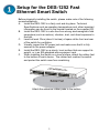
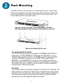
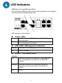
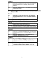
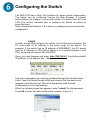
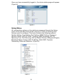
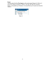
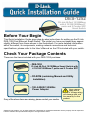
DES-1252 D-Link 48-Port 10/100Mbps with 4 10/100/1000Base-T ports and 2 Combo SFP Smart Switch Before Your Begin This Quick Installation Guide gives step-by-step instructions for setting up the D-Link DES-1252 Fast Ethernet Smart Switch. The model you have purchased may appear slightly different from those shown in the illustrations. For more detailed information about the switch, its components, making network connections and technical specifications, please refer to the User’s Manual on the CD included with your switch. Check Your Package Contents These are the items included with your DES-1252 purchase: • DES-1252 D-Link 48-Port 10/100Mbps Smart Switch with 4 10/100/1000Base-T ports and 2 Combo SFP • CD-ROM (containing Manual and Utility Installation) • 100–240VAC 50/60Hz Power Adapter If any of the above items are missing, please contact your reseller. Using a power supply with a different voltage rating will damage and void the warranty for this product. ©2006 D-Link Systems, Inc. All rights reserved. Trademarks or registered trademarks are the property of their respective holders. Software and specifications subject to change without notice. Setup for the DES-1252 Fast Ethernet Smart Switch Before physically installing the switch, please make note of the following recommendations: A. Install the DES-1252 in a fairly cool and dry place. Technical Specifications such as operating temperatures and, other important information can be found in the manual located on the supplied CD. B. Install the DES-1252 in a site free from strong electromagnetic field generators (such as motors), vibration, dust, and direct exposure to sunlight. C. Leave at least 10cm (about 4 inches) of space at the front and rear of the switch for ventilation. D. Visually inspect the DC power jack and make sure that it is fully secured to the power adapter. E. Install the DES-1252 on a sturdy, level surface that can support its weight, or in an EIA standard-size equipment rack. F. When installing the Switch on a level surface, attach the rubber feet to the bottom of each device. The rubber feet cushion the switch and protect the switch case from scratching. Attach the adhesive rubber pads to the bottom 2 Rack Mounting The DES-1252 can be mounted in an EIA standard-size, 19-inch rack, which can be placed in a wiring closet with other equipment. Attach the mounting brackets to both sides of the Switch (one at each side), and secure them with the provided screws. Use the screws provided. Then use screws provided with the equipment rack to mount the Switch in the rack. Mount the Switch in the rack Connecting Network Cables The DES-1252 has 48 ports that support 10/100Mbps Fast Ethernet; it also has 4 10/100/1000Base-T Ports and 2 Combo SFPs. It runs full/half duplex transfer mode for 10/100Mbps and full duplex transfer mode for 1000Mbps. Each port on the DES-1252 supports AutoMDI/MDI-X. Auto-MDI/MDI-X is a feature that enables the switch to auto sense what kind of cable is used on a port (straight or crossover). This allows any type of cables to be used with the switch regardless of what device is being connected. AC Power The Switch utilizes an AC power supply of 100~240V AC, 50~60Hz. The power switch is located at the rear of the unit adjacent to the AC power connector and the system fan. The switch’s power supply will adjust to the local power source automatically and may be turned on without having any or all LAN segment cables connected. 3 Connecting The DES-1252 Fast Ethernet Smart Switch To Your Network Front Panel Twisted-Pair Ports Mini GBIC Ports ┌─────────────────────────────┐ ┌┘ └┘ LED Indicators └─┘ 10/100/1000 Base-T Twisted Pair Ports 10/100 BASE-TX Twisted Pair Ports (Port 1~48) The DES-1252 is equipped with 48 Fast Ethernet twisted pair ports that are auto-negotiable 10/100Mbps and also support auto MDI/MDIX crossover detection. All these 48 ports can operate in half- and fullduplex modes. 10/100/1000 BASE-T / Mini GBIC Combo Ports (Option Port 49~50) The Switch is also equipped with two combo 10/100/1000 Base-T / Mini GBIC ports, supporting optional 100BASE-FX or 1000BASESX/LX Mini GBIC modules for fiber uplinks. 10/100/1000 BASE-T Twisted Pair Ports (Port 51~52) Finally there are 2 Gigabit twisted pair ports that are auto negotiable 10/100/1000Mbps with full auto MDI/MDIX crossover detection support that can also operate in half- and full- duplex modes. [Note: If the port is set to “Forced Mode”, Auto-MDI/MDIX is disabled] 4 LED Indicators LED stands for Light-Emitting Diode. The front panel LEDs provides instant status feedback and simplifies monitoring and troubleshooting tasks. LED indicators of the Switch On Off Power LEDs When the Power LED light is on, the Switch is receiving power. When the Power LED light is off, the power cord is not or improperly connected. CPU LEDs ( Management Indicator) Blinking When the CPU is working, the CPU LED is blinking. Off The CPU is idle. Ports 1 ~ 48 Status LEDs Link/Act On When the Link/Act LED light is on, the respective port is successfully connected to an Ethernet network. Blinking When the Link/Act LED is blinking, the port is transmitting or receiving data on the Ethernet network. Off No link. 5 100Mbps On When the 100Mbps LED light is on, the respective port is connected to a 100Mbps Fast Ethernet network. Off When the respective port is connected to a 10Mbps Ethernet or no link. Option Ports 49~50 10/100/1000 Base-T / Mini-GBIC Status LEDs FX Link On When the FX Link LED light is on, the respective port is connected to a 100 or 1000Mbps Ethernet network. Off No link or linking the copper ports. Link/Act On When the respective combo port is connected to a network, the Link/Act LED light is on. Blinking When the LED is blinking, the respective combo port is transmitting or receiving data on a network. Off No link. 1000Mbps On When the 1000Mbps LED light’s on, the respective port is connected to a 1000Mbps Gigabit Ethernet network. Off When the respective port is connected to the 100Mbps Fast Ethernet or no link. 100Mbps On When the 100Mbps LED lights on, the respective port is connected to a 100Mbps Fast Ethernet network. Off When the respective port is connected to a 1000Mbps Gigabit Ethernet network or no link. 6 Ports 51~52 10/100/1000 Base-T LEDs Link/Act On When the Link/Act LED light is on, the respective port is successfully connected to an Ethernet network. Blinking When the Link/Act LED is blinking, the port is transmitting or receiving data on the Ethernet network. Off No link. 1000Mbps On When the 1000Mbps LED light is on, the respective port is connected to a 1000Mbps Gigabit Ethernet network. Off When the respective port is connected to a 10Mbps Ethernet or 100Mbps Fast Ethernet network, or no link. 100Mbps On When the 100Mbps LED light is on, the respective port is connected to a 100Mbps Fast Ethernet network. Off When the respective port is connected to a 10Mbps Ethernet or 1000Mbps Gigabit Ethernet network. 7 Installing the SmartConsole Utility The SmartConsole Utility allows a user to monitor and configure multiple D-Link Web-Smart Switches from a workstation connected to the network. Follow these steps to install the SmartConsole Utility: 1. Insert the Utility CD in the CD-Rom Drive. 2. From the Start menu on the Windows desktop, choose Run. 3. In the Run dialog box, type D:\SmartConsole Utility\setup.exe ( where D:\ represents the drive letter of your CD-ROM) your CD-Rom drive is located) and click OK. 4. Follow the on-screen instructions to install the utility. 5. Upon completion, go to Program Files -> SmartConsole Utility and execute the SmartConsole utility. (Figure 1.) Figure 1. SmartConsole Utility 8 Configuring the Switch The DES-1252 has a Web GUI interface for smart switch configuration. The Switch can be configured through the Web Browser. A network administrator can manage, control and monitor the switch from the local LAN. This section indicates how to configure the Switch to enable its smart functions. Note: Use Internet Explorer 5.5 or above to properly access and view the configuration.. Login In order to login and configure the switch via an Ethernet connection, the PC must have an IP address in the same range as the switch. For example, if the switch has an IP address of 192.168.0.1, the PC should have an IP address of 192.168.0.x (where x is a number between 2 and 254), and a subnet mask of 255.255.255.0. Open your web browser and enter http://192.168.0.1 (the factory-default IP address) in the address box. Then press <Enter>. Figure 2 The web configuration can also be accessed through the SmartConsole Utility. Open the SmartConsole Utility and double-click the switch as it appears in the Monitor List. This will automatically load the web configuration in your web browser. When the following logon box appears, enter "admin" for the password. Press Ok to enter the main configuration window. (Figure 3.) Figure 3 9 Once you have successfully logged in, the device status page will appear. (Figure 4) Figure 4 Setup Menu All configuration options on the switch are accessed through the Setup menu on the left side of the screen (Figure 5). Click on the setup item that you want to configure. The menu contains the following options: System Setting, Trap Setting, Port Setting, SNMP Setting, Password Access Control, 802.1Q VLAN, Trunking, IGMP Snooping, 802.1D Spanning Tree, Port Mirroring, 802.1p Default Priority, Safeguard Engine, Broadcast Storm Control, 802.1X Setting, Static MAC, Dynamic Forwarding Table and Statistics. (Figure 5). Figure 5 10 Tool You can also find the Tool menu on the main page (Figure 6). Click on it and scroll down as shown in Figure 6, and you can see four options: Reset, Config Backup & Restore, Firmware Backup & Upload and System Reboot. Figure 6 11