1
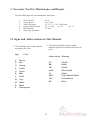
Standard PS-P61
Punch Stapler
Service Manual
Provided By
http://www.MyBinding.com
http://www.MyBindingBlog.com
SERVICE MANUAL
PS-P61 Punch Staple
510 Kuze Ooyabu-cho Minami-ku, Kyoto 601-8206, Japan
Phone:+81-75-934-6700, Fax:+81-75-934-6708, www.horizon.co.jp
Kyoto,Japan
FOREWORD
Punch Staple
Model PS-P61
This manual is designed to help you to keep the machine in a good operating
condition. Read, study and keep this manual in a safe and convenient place.
Do not perform any maintenance until you read and
understand the instructions in this manual.
If you have questions regarding maintenance or this publication,
please contact our service division.
The machine design and specifications are subject to
change without notice.
030701/PSP61/03E/DV
I
US501008-03
Safety Instruction
1. Read and understand all safety instructions with a signal
WARNING,
CAUTION. If safety instructions are ignored, personal injury will
and
result.
2. HORIZON INTERNATIONAL INC. cannot anticipate every possible situation that might involve a potential hazard. The instruction in this manual are
therefore not all inclusive.
3. Be sure to unplug the power cord when replacing the parts or repairing the
machine.
4. Take care with the rotating parts when the machine is operated with the covers
being opened.
5. Use the original HORIZON spare parts when replacing the parts.
II
I Necessary Tool for Maintenance and Repair
Use the following tools for maintenance and repair.
1.
2.
3.
4.
5.
6.
Screw Driver
Screw Driver
Allen Wrenches
Open-ended Wrench
Box Wrench
Snap-ring Expander
No. 2
6 to 7 mm
1.5, 2, 2.5, 3, 4, 5, and 6 mm
5.5 x 7 mm
8 x 10
13 x 17
5.5 mm
II Signs and Abbreviations in This Manual
1. The following signs in this manual
represent wire color.
Sign
2. The following abbreviations in this
manual represent electronic and electrical
parts.
Color
Abbreviation Meaning
C
R
O
Y
G
B
V
H
W
D
S
Brown
Red
Orange
Yellow
Green
Blue
Violet
Gray
White
Black
Transparent
CL
BK
SW
mSW
M
LED
VR
RY
III
Clutch
Brake
Switch
Microswitch
Motor
Light Emitted Diode
Potentiometer
Relay
Contents
FOREWORD .......................................................................................................................... I
Safety Instruction ................................................................................................................... II
I Necessary Tool for Maintenance and Repair ................................................................... III
II Signs and Abbreviations in this manual ........................................................................... III
1. PS-P61 Specifications ...................................................................................................... 1
2. Operation Overview ........................................................................................................ 2
3. Sheet Flow ........................................................................................................................ 3
4. How to Remove Cover .................................................................................................... 4
5. Sensors and Electronic Parts Descriptions ................................................................... 5
6. Sensor Location and Descriptions ................................................................................. 6
7. Transport Belt Drive Descriptions ................................................................................ 7
8. Troubleshooting ............................................................................................................... 8
9. LED and ConnectorDescriptions on P.C.B. .................................................................. 11
10. Power & Signal Line Diagram ..................................................................................... 12
11. Panel Sensor Line Diagram .......................................................................................... 13
12. Staple Unit Inside Line Diagram ................................................................................. 14
13. Power Supply Line Diagram ........................................................................................ 15
14. Punch Unit and Sensor ................................................................................................. 16
15. Timing Chart 1 .............................................................................................................. 17
16. Timing Chart 2 .............................................................................................................. 18
17. Timing Chart 3 .............................................................................................................. 19
18. Check Mode ................................................................................................................... 20
IV
1. PS-P61 Specifications
Product
Staple and Punch Unit for QC-P8/P10
Integrated Model
QC-P8, QC-P10
Jobs
A4 : Corner Staple, Top Staple, and other Side Corner Staple
A3: Corner Staple
NOTE - Only corner staple can be done with optional punch.
- Two hole punch (option) can be performed only on A4 size.
Sheet Size with Operation Panel A4 and A3
NOTE - Sheet size must be within +,-0.5 mm.
Sheet Size
Width : Maximum 298 mm (11.8") Minimum : 182 mm (7.2")
Length : Maximum 432 mm (17") Minimum : 257 mm (10.2")
NOTE - Other side corner staple and top staple are limited in size.
Sheet Quality
Normal Paper
Stapling and Punching Thickness 10 Sheets of 135 gsm (36# Bond)
Sheet Thickness
53 to 135 gsm (16# Bond to 36# Bond)
Optional Punch Capacity Up to 105 gsm of normal paper
Production Speed
25 Sets/min. (Corner Staple)
15 Sets/min. (Top Staple, Other Side Corner Staple and Staple with Punch)
Transport Method
Connecting Section : Roller Transport
Producing Section : Belts Transport
Detector
Sheet Jam, No Staple, Door, Staple Trouble, Punch Trouble, and Full Tray
(LEDs illuminate on operation panel.)
Counter
4 digits (For Maintenance)
Drive
DC Motor : 3 x 24 V DC Solenoid : 4 x 24 V/35 W
DC Motor : 1 x 24 V (with Punch)
Power
100 V 50/60 Hz, 115 V 60 Hz, 230 V 50 Hz
Power Consumption 150 W
Machine Dimensions Tray Open : 1,115 x 562 x 582 mm (43.9" x 22.2" x 22.9")
(W x D x H)
Tray Close : 775 x 562 x 580 mm (30.6" x 22.2" x 22.9")
Machine Weight
77 kg (170 lb)
1
2. Operation Overview
1. Pile sheets into bins and turn on power switch.
- Staple unit will be reset if staple unit is not at home position before power is on.
- LED conditions of operation panel
Jog Guide
Illuminates at the current position. Not illuminates when irregular
sheets are used.
Staple Mode
Illuminates at the angled side staple position.
Punch
Not illuminates.
Jog Time
1 time lamp illuminates.
2. Press option button on collator.
- Option LED illuminates.
- Gate in collator moves.
3. Set jog guides according to sheets.
- LED in the selected sheet size illuminates.
4. Select required mode with staple mode button.
- LED illuminates in different position as staple button is pressed.
Staple unit moves to set position a few seconds after staple mode is selected.
NOTE
- In the case of other side corner staple or top staple, staple mode cannot be selected
because of limited sheet size.
- In the case of staple with punch, staple mode cannot be selected because of limited
sheet size.
5. Set receiving tray and receiving tray guide according to sheet size.
6. Press check button of collator twice. As collator starts, transport unit will transport a set of
sheets. The set is stapled and/or punched and delivered to receiving tray.
7. Press start button of collator. Collator starts collating and sets of sheets are produced.
When miss/double or other troubles happen on collator, collating job stops with LED illuminated.
Collator's Error : Sheet jam, misfeed, and double feed are indicated on panel of collator.
PS-P61's Error : QC-P10 : Option error message is indicated on collator.
QC-P8 : Receiving tray lamp illuminates on collator.
PS-P61 : Monitor lamp illuminates.
8. When preset counter reaches to set number, collating stops and then transport unit stops.
- In the case of the number of sets are not input in preset counter, collator stops because
sheets run out, or because receiving tray of PS-P61 is full.
2
3. Sheet Flow
Jog Guide 1
Forward Roller
Gate
Transport Unit
Transport Rollers
Delivery Roller
Staple Unit
Sheet Feed Sensor
B4 Stopper
Receiving Tray
Sheet Jog Sensor
Transport Belt
Jog Guide 2
Stopper Sensor
Stopper
A. Corner Staple with A4 and A3 Sheet Size (8.5" x 11"/11" x 17")
1.
2.
3.
4.
5.
6.
7.
A set of collated sheets are delivered to transport unit.
A set of sheets are transported by transport rollers and pass sheet feed detector.
Transport belt and forward roller transport a set of sheets to stopper.
Transport belt stops.
Jog solenoids is activated and jog sheets.
Stapler staples sheets.
Delivery roller lowers and transport belt delivers a set of sheets to receiving tray.
B. Top Staple with A4 Sheet Size (8.5" x 11")
Staple unit moves to top staple position and is ready to staple. The procedures 1 to 6 are the
same as A.
7.
8.
9.
10.
Delivery roller lowers and transport belt delivers a set to the second staple position.
Jog solenoids is activated and jog sheets.
Stapler staples sheets.
Transport belt delivers a set of sheets to receiving tray.
C. Other Side Corner Staple with A4 Sheet Size (8.5" x 11")
Staple unit moves to the other side corner staple position and is ready to staple. The rest
procedures are the same as A.
D. Punch
The procedures 1 to 6 are the same as A.
7. Punch punches sheets.
8. Delivery roller lowers and transport belt delivers a set to receiving tray.
3
4. How to Remove Cover
B4-6BC (4 pcs)
Rear Cover (L)
Front Cover (U)
B4-8Zpan (4 pcs)
4
5. Sensors and Electronic Parts Descriptions
S/N
001001
to
099001
Motor Driver
Transport Belt Motor
Transport Unit Motor
Brake
S/N
002901
to
008917
Transport Unit Open Sensor
Power Supply Box
(Switch, Power Supply (5 V and 24 V), Breakers)
Clutch
Sheet Feed Sensor
Punch Unit (Motor and Reset Sensor)
Staple Unit
(Motor, Reset Sensor and No Staple Sensor )
Pulse Sensor
Door Open Sensor Switch
Stopper Sensor
Jog Solenoid 1
Sheet Jog Sensor
Full Tray
(Receiver) P.C.B. (QPP-263A)
Counter
Full Tray (Projector)
P.C.B.(QPP-263A)
Control P.C.B. (QPW-457)
Panel P.C.B. (QPW-458)
Stopper Solenoid
B4 Stopper Solenoid
Jog Solenoid 2
Transport Roller Solenoid
From
S/N
100001
Motor Driver
Transport Belt Motor
5
6. Sensor Location and Descriptions
Jog Guide 1 Position Sensor
Staple Motor
Staple Home Position Sensor
Jog Guide 2 Position Sensor
Sketch of Staple Cabinet
6
7. Transport Belt Drive Descriptions
(1) Applied Serial Number : S/N from 002901 to 008917
Brake
Transport Belt Motor
Clutch
Timing Belt
Sheet Pulse Sensor
Transport Belt
Sketch of Inside of Staple Unit
(2) Applied Serial Number : S/N 001001 or up
Motor
Coupling
Motor Driver
Transport Belt
7
8. Troubleshooting
A. Staple position (top staple) varies by more than 10 mm.
(Cause)
Delivery roller does not lower
enough and not deliver a set
of sheets. Transport belt is
dirty. Clearance between
clutch and brake gets wider.
(Remedy 1)
Adjust delivery roller so that it lowers enough.
- Adjust solenoid so that delivery roller touches transport
belt and spring is compressed about 1 mm when solenoid
activates.
(Remedy 2)
Clean transport belt with alcohol soaked cloth.
(Remedy 3)
Check the clearance between clutch and brake. Standard
clearance is 0.15 (+,-0.05) in both clutch and brake.
Applied Serial Number : S/N from 002901 to 008917
B. When sheet jam 1 lamp illuminates.
(Cause)
(Remedy)
Sheets are jammed in transport
Open transport unit and remove jammed sheets. And
unit or transport unit is open.
close transport unit firmly.
C. When sheet jam 2 lamp/ sheet jam 3 lamp illuminates.
(Cause)
Sheets are jammed in staple
cabinet.
(Remedy 1)
Press eject button.
(Remedy 2)
Pull out staple cabinet and remove jammed sheets. In the
case sheet jam 3 lamp illuminates, lift support guide unit
and remove jammed sheets.
D. When punch trouble lamp flashes.
(Cause)
Punch unit is locked.
Attention
Punch Capability: up to 10 sheets
of 105 gsm normal paper.
(Remedy)
Turn off power switch of collator, then turn on again
after a few seconds. Press eject button, open staple
cabinet and remove jammed sheets.
8
8. Troubleshooting
E. When no staple/staple trouble lamp illuminates.
(Cause 1)
Out of staples.
(Remedy 1)
Refill staples.
(Cause 2)
Staple unit head is not set on
the proper position.
(Remedy 2)
Press eject button to reset staple unit.
F. When no staple/staple trouble lamp flashes.
(Cause)
(Remedy)
Staple unit is locked because of
Turn off power switch of collator, then open staple
staple jam.
cabinet and remove jammed sheets or staples. Close
staple cabinet, turn on power switch of collator and press
eject button. Staple unit will be reset. Check for proper
stapling by collating several sets (7 to 8 sets).
G. When door lamp illuminates.
(Cause)
Staple cabinet or rear cover is
open.
(Remedy)
Close staple cabinet or rear cover.
H. When receiving tray lamp illuminates.
(Cause)
Receiving tray is full, or
sheets are not delivered
completely.
(Remedy)
Remove sheets from receiving tray, or delivery area.
I. When sheets are delivered without stapling. (Collating Continues.)
(Cause)
Staples are not fed to stapling
position in staple unit.
(Remedy 1)
Set unnecessary sheets on bin, and check for proper
stapling by collating several sets (7 to 8 sets).
(Remedy 2)
Open staple unit, pull up and release staple cartridge
and clean staple feed roller with alcoholic soaked cloth.
9
8. Troubleshooting
J. When sheets are delivered without stapling. (Collating stops.)
(Cause)
Collated sheets are not jogged
neatly.
(Remedy 1)
Open staple cabinet and check whether jog guide is
positioned to sheet size properly.
(Remedy 2)
Straighten curled sheets, and fan them well.
(Remedy 3)
Press jog switch and select 2-time jog.
K. When circuit breaker trips.
(Remedy)
Turn off power switch of collator. Check inside of
collator for obvious problems such as jammed sheets. If
there is a problem, remove the cause. Reset circuit
breaker a few minutes after turning off power switch.
Push two left breakers to reset. Push up two right breakers to reset.
10
9. LED and Connector Descriptions on P.C.B.
CON8
CON10
L19
L18
L17
CON1
CON5
CON3
CON9
L5
L6
L7
L2
L1
CON12
CON7
L16
CON6
CON4
L15
L14
L13
CON2
CON11
L12
L11
L10
L9
Control P.C.B. QPW457
L8
LED Indication
L1
Staple Reset Position
Illuminates at the reset position.
L2
No Staple
Illuminates when staples remain in cartridge.
L5
Punch Home Position
Illuminates at the home position.
L6
No Starting PS-P61
Illuminates when PS-P61 cannot start.
L7
Staple/Punch
Illuminates when punch is selected.
L8
Staple Home Position
Illuminates at home position.
L9
Not Used
Illuminates when transport unit is closed.
L10
Transport Unit Open Sensor
L11
Not Used
L12
Sheet Feed Sensor
Illuminates when no sheets under sensor.
L13
Sheet Jog Sensor
Illuminates when no sheets over sensor.
L14
Stopper Sensor
Illuminates when no sheets over stopper.
L15
Staple Cabinet Rear Cover Open
Illuminates when cover is open.
L16
Staple Mode Button
Illuminates when button is pressed.
L17
Eject Button
Illuminates when button is pressed.
L18
Jog Button
Illuminates when button is pressed.
L19
Punch Button
Illuminates when button is pressed.
Connector
CON1
To Staple Unit
CON7
To Punch Unit
CON2
To Sheet Size Sensor and Panel P.C.B.
CON8
To Connector which connects Collator
CON3
To Solenoids and Transport Motor
CON9
To Power Supply 5V 24V
CON4
To Sensors
CON10
To Panel P.C.B Switch
CON5
To Transport Roller Solenoid and B4 Stopper
CON11
To Sensors
CON6
To Indicate Panel P.C.B LED
CON12
To Staple Motor, Clutch, Blake and Pulse Sensor
11
CON7
CON3
CON5
CON6
CON4
CON2
CON1
B4 Stopper Solenoid
Collator Connecting Cable
Indication P.C.B.
Transport Roller
QPW 457
Punch unit
Stopper Solenoid
CON7
CON8
CON1
CON5
CON3
CON9
Sheet Jog Solenoid 1
Staple Cabinet
Rear Cover Open Sensor
Sheet Jog Solenoid 2
CON12
Stopper Sensor
CON10
12
Sheet Jog Sensor
Trans. Belt Motor
Trans. Unit Motor
Full Tray Sensor
(Receiver)
CON4
Counter
Brake
Clutch
Pulse Sensor (Sheet)
CON11
Staple Home Position Sensor
Pulse Sensor (Staple)
CON2
Transport Unit Open Sensor
Indication P.C.B.
QPW 457
Staple Move Motor
Power Supply Unit
Applied Serial Number :
S/N from 002901 to 008917
Full Tray Sensor
(Projector)
CON6
Sheet Feed Sensor
10. Power & Signal Line Diagram
Staple Unit
CON7
CON3
CON5
CON4
CON6
CON2
CON1
B4 Stopper
Solenoied
Collator Connecting Cable
Indication P.C.B.
Transport Roller
Punch Unit
QPW457
Motor Driver
P.C.B.
Stopper Solenoid
CON7
CON8
CON1
CON5
CON3
CON9
Sheet Jog Solenoid 1
CON12
Sheet Jog Solenoid 2
CON10
13
Staple Cabinet
Rear Cover Open Sensor
Sheet Jog Sensor
Stopper Sensor
Trans. Belt Motor
CON6
CON4
Counter
Pulse Sensor (Sheet)
CON11
Full Tray
Sensor
(Receiver)
Staple Home Position Sensor
Pulse Sensor (Staple)
Trans.Unit Open Sensor
CON2
Full Tray
Sensor
(projector)
Trans. Unit Motor
Indication P.C.B.
QPW457
Staple Move Motor
Power Sopply
Unit
Applied Serial Number :
S/N 001001 or up
Sheet Feed
Sensor
11. Power & Signal Line Diagram
Staple
Unit
B5 Longer Edge Size Sensor
B5 Shorter Edge Size Sensor
A4 Longer Edge Size Sensor
A4 Shorter Edge Size Sensor
B4 Longer Edge Size Sensor
B4 Shorter Edge Size Sensor
A3 Longer Edge Size Sensor
A3 Shorter Edge Size Sensor
12. Panel Sensor Line Diagram
To Control P.C.B. QPW457
CON7
CON3
CON5
CON4
CON6
CON2
CON1
Indication P.C.B. QPW458
14
13. Staple Unit Inside Line Diagram
R
1
7
2 3
8 9
4
5
10
6
Ground for Staple
G
11 12
W
G
V
D
H
No
Staple
Motor
O
B
Reset Unit P.C.B.
View from Arrow Mark (Leading Cable)
Side View of Staple Unit
No Staple Sensor
Motor
Fixed Sensor
Connector QR/P1-12P-C
15
14. Transport Belt Motor Driver Wiring
Function Select Switch
Applied Serial Number : S/N 001001 or up
CN2
CN1
4321
Transport Belt Motor
To Control P.C.B.
CN1
To Transport Belt
1 Green 2 Black
3 Blue
4 Red 5 Yellow 6 White CN2
S/N099999 or before
To MotorTo Control P.C.B.
1 To Connector 4-10
None
2 To Connector 3-10
3 None
4 None
5 None
6 None
7 None
8 None
9 None
10 None
11 To Connector 3-9
12 To Connector 11-4
None
To Connector 4-10
To Connector 3-10
None
None
None
None
None
None
To Connector 3-9
To Connector 11-4
S/N100001 or after
The following list is shown the function select switch position in normal operation condition.
The machines having S/N 007006 or up equip with ver. 3.03 rom.
ROM Version
Function Select Switch
3.00
3.03
3.20
Normal Position Another Position Normal Position Normal Position
1.Automatic Current
Reducing Function
ON
2.Step Select Switch
ON 1.8゜
OFF
3.Input Pulse Select Switch
OFF
2 pulse
24 V
4.Power Voltage Select Switch ON
ON
ON
0.9゜
/ stp
OFF
OFF
ON
1 pulse
OFF
OFF
OFF
36 V
ON
ON
OFF
16
Noise Filter
SUP-B3G-ER
Receptacle
WCF1041B
G3NE-205T-DC5V
S S R
L C A 1 0 0 S - 2 4
NRF110-2A
17
NRF-110-3A
Power Supply
L C A 1 0 S - 5
Power Supply
+24V
3
+5V
+24V COM
4
1
+24V COM
5
5V COM
Remote +
6
2
Remote -
7
15. Power Supply Line Diagram
1 23 4 5 6 7 8
NRF1100-1A SD
NRF1100-3A AD
16. Punch Unit and Sensor
Reset Sentor
1
2
3
4
5
6
7
8
Motor
SMR-08V-B
R
D
Sheet Sensor EE-SPY-302
Stopper Sensor
Y
G
B
Punch Unit
SMR-03V-B
1
2
3
+5V
OUT
COM
18
19
No Staple Monitor
Punch
Staple
Sheet Feed Motor
Transport Belt
Sheet Jog Solenoid 2
Sheet Jog Solenoid 1
Stopper Solenoid
Sheet Hold Solenoid
Stopper Sensor
Sheet Jog Sensor
Sheet Feed Sensor
Staple/Punch
No Starting PS-P61
Collating Error
In Collating
500mS
Side Staple Correct Function
About 900mS
About 250mS
700mS
500mS
Unneatly Jogged Sheets / Option Error
300mS
300mS
700mS
700mS
700mS
300mS
700mS
300mS
6-second Output
Unneatly Jogged Sheet Check
Jogged Sheet Check
Unneatly Jogged Sheets
700mS
Sheets are ejected.
Sheet Jog Condition Check
No Starting Output
17. Timing Chart 1
20
B4 Stopper
Clutch
No Staple Monitor
Punch
Staple
Sheet Feed Motor
Transport Belt
Sheet Jog Solenoid 2
Sheet Jog Solenoid 1
Stopper Solenoid
Trans. Roller Solenoid
Stopper Sensor
Sheet Jog Sensor
Sheet Feed Sensor
No Starting PS-P61
In Collating
500mS
500mS
Top Staple Correct Function
About 250mS
When staple lock timer is not reset in one second or punch is not reset
in two seconds, each motor stops and nostaple monitor flashes.
No staple monitor illuminates.
Staple Lock Timer
For 2 Seconds
Punch Lock / Option Error
300mS
300mS
The timig is different according to sheet size.
300mS
300mS
700mS
Sheet Jog Condition Check
No Starting Output
18. Timing Chart 2
(Applied Serial Number : S/N from 002901 to 008917)
21
700mS
B4 Stopper
No Staple Monitor
Punch
Staple
Sheet Feed Motor
Top Staple Correct Function
About 250mS
The timing is different according to sheet size.
500mS
No Starting Output
When staple lock timer is not reset in one second or punch is not reset
in two seconds, each motor stops and nostaple monitor flashes.
No Staple monitor illuminates.
Staple Lock Timer
For 2 Seconds
Punch Lock / Option Error
300mS
300mS
Sheet Jog Solenoid 2
Transport Belt
300mS
300mS
500mS
Sheet Jog Condition Check
Sheet Jog Solenoid 1
Stopper Solenoid
Trans. Roller Solenoid
Stopper Sensor
Sheet Jog Sensor
Sheet Feed Sensor
No Starting PS-P61
In Collating
For ROM ver. 3.21 or above,
transport roller does not hold
the sheets before second stitching.
19. Timing Chart 2
( Applied Serial Number : S/N 001001 or up )
20. Timing Chart 3
(Applied Serial Number : S/N from 002901 to 008917)
In Collating
Sheet Feed Sensor
Sheet condition Check
Sheet Jog Sensor
Stopper Sensor
700mS
Trans. Roller Solenoid
Stopper Solenoid
300mS
Sheet Jog Solenoid 1
300mS
Sheet Jog Solenoid 2
Transport Belt
500mS
700mS
Sheet Feed Motor
Staple
About 250mS
Punch
No Staple Monitor
Clutch
B4 Stopper
B4 Other Side Corner Staple Correct Function
22
21. Timing Chart 3
(Applied Serial Number : S/N 001001 or up )
In Collating
Sheet Feed Sensor
Sheet Jog Condition Check
Sheet Jog Sensor
Stopper Sensor
700mS
Trans. Roller Solenoid
Stopper Solenoid
300mS
Sheet Jog Solenoid 1
300mS
Sheet Jog Solenoid 2
Transport Belt
500mS
700mS
Sheet Feed Motor
Staple
About 250mS
Punch
No Staple Monitor
B4 Stopper
B4 Other Side Corner Staple Correct Function
23
22. Check Mode
1. Staple Unit Check Mode
- Turn on power with eject button pressed.
- Every time eject button is pressed, staple works.
- Lock sensor works during check mode. If staple lock continues for more than 1 second,
staple motor stops and staple trouble lamp on monitor flashes
2. Punch Unit Check Mode
- Turn on power with eject button pressed.
- Press staple mode switch to select "corner staple 0˚".
- Every time eject button is pressed, punch works.
NOTE
- Operate punch unit with 3 to 4 seconds intervals. Otherwise, motor or controller may be
broken. Lock sensor works during check mode. If punch lock continues for more than 2
seconds, punch motor stops and punch trouble lamp on monitor flashes.
3. Check on Complete Functions
- Turn on power with staple mode button and eject button pressed at the same time. And
complete function of PS-P61 will work successively except punch.
NOTE
- Operating PS-P61 with staple cartridge in check mode may cause staple jam. When
operating in check mode, remove staple cartridge or insert sheets into staple section.
- When each of monitor lamp flashes, PS-P61 does not work. Turn off power and turn on
again.
- Check mode does not reset until power is turned off. Turn on again when collating job is
started.
24