1
AMAX panel 4000 / AMAX panel 4000 EN
ICP-AMAX4-P1 / ICP-AMAX4-P2-EN / ICP-AMAX4-P3-EN
en
Quick Start Guide
AMAX panel 4000 / AMAX panel 4000
EN
Table of Contents | en
3
Table of contents
1
Short information
4
2
System overview
5
3
Installation
7
3.1
System Power Up
7
3.2
System Status Indicator
7
3.3
Installer and User Code Commands
7
3.4
Prerequisites for Certification conform Installation
9
4
Configuration
10
4.1
Programming with Keypad
10
4.1.1
LCD Keypad Menu Programming
10
4.1.2
LED/Icon LCD Keypad Address Programming
10
4.2
Reset to Factory Default Settings
11
4.3
LCD Menu Programming
12
4.4
Address Programming
20
4.4.1
Communication and Report Setting
20
4.4.2
Zone Programming
26
4.4.3
Output Programming
38
4.4.4
Access Codes
43
4.4.5
System Programming
49
5
Troubleshooting
63
6
Technical Data
66
Bosch Sicherheitssysteme GmbH
Quick Start Guide
2013.07 | 03 | F.01U.267.113
4
1
AMAX panel 4000 / AMAX panel 4000
EN
en | Short information
Short information
Thank you for choosing the AMAX panel 4000. This is a flexible, reliable, convenient, and easyto-use alarm system. It has 16 wired zones on board, expandable up to 64 wired and wireless
zones.
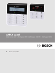
This Quick start guide is provided with the system to give basic information about the system
wiring, components, and describe how to simply program and operate the system with IUIAMAX4-TEXT keypad, IUI-AMAX3-LED16 keypad, IUI-AMAX3-LED8 keypad, ICPKP8-LED keypad,
or ICP-KP8L-Icon LCD keypad. As the system includes a large number of programmable
functions and options, we suggest reading the complete installation manual. For detailed
operation method, please refer to the User Guide.
2013.07 | 03 | F.01U.267.113
Quick Start Guide
Bosch Sicherheitssysteme GmbH
AMAX panel 4000 / AMAX panel 4000
EN
2
System overview | en
5
System overview
Information:
Customer:
Location:
Account #:
Installer:
Date:
Bosch Sicherheitssysteme GmbH
Quick Start Guide
2013.07 | 03 | F.01U.267.113
6
AMAX panel 4000 / AMAX panel 4000
EN
en | System overview
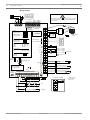
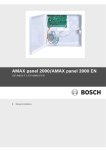
Wiring Diagram
R
G
B
Y
Risk of shock if N,L1 or
is connected incorrectly.
For operation safety, the ground terminals must
be connected.
_ 900mA
AUX 1: <
_ 900mA
AUX 2: <
TIP
TH
RH
RING
R
G
B
Y
AUX1 AUX2 AUX2 AUX1
+12V +12V -
Keypads:
1=
2=
AUX Power
GND
AC
AC
I ∑
_
< 2000mA
IUI-AMAX4-TEXT
IUI-AMAX3-LED16 3 =
IUI-AMAX3-LED8
4=
Transformer
Bosch Option
_ 900mA
Bus 2 <
18VAC@50VA
+
Battery
12V 7Ah
_ 18Ah
12V <
5-16 Inst. Guide
Keypads:
IUI-AMAX-LED8
IUI-AMAX-LCD8
Bosch Option
_ 900mA
Bus 1 <
1=
2=
I/O Moduls:
DX2010
DX3010
DX4010
Adr. 103 - 108
Adr. 150 - 151
Adr. 253
Communicators:
DX4020G
B426
Adr. 134
Adr. 134(6) / 250(9)
RF Receiver:
RF3227E
RFRC-OPT
Y
Y
G
G
B
B
R
R
+12V
P0+4
+12V
P0+3
+12V
P0+
COM
P0-2
COM
P0-1
PO+4: _
<
_
PO+3: <
_
PO -2: <
_
PO -1: <
L16
1=
1= (1)
230V ~50Hz
230mA
Fuse 1 A
750mA
750mA
500mA
500mA
supervised
100 Ω - 2,2 k
COM
L15
Factory
Default
L14
Program Key Port
3
COM
1
3
2
L13
Zones
L12
♥
Slow flash: Normal state
On: Trouble state
Off: Trouble state
PO-5
+12V
2
L11
L10
Zones
Wachdog
output
<100mA
_
3
COM
3
COM
2
+
0V
L9
Tamper
L1a
L1b
L2
L3
COM
L4
L5
L6
COM
L7
COM
L8
IUI-AMAX3 +4 Keypad
3
3
Fire
2
Intrusion
3
2
B
G
3
1
Y
COM
2
1 Tamper Switch
2 Zone Switch
3 EOL 2,2 k
1
3
Z1
2
R
3
2013.07 | 03 | F.01U.267.113
Quick Start Guide
Bosch Sicherheitssysteme GmbH
AMAX panel 4000 / AMAX panel 4000
EN
3
Installation | en
7
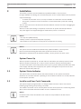
Installation
This system / product must be installed by a qualified installer / service person.
During installation and wiring, the control panel power source must be switched-off to prevent
equipment damage.
–
To switch off the Power Source, an easy accessible circuit breaker must be available.
–
The System / product must be connected to a socket-outlet with a protective earthing
contact
The User has to disconnect all Telecommunication Network Connectors before unplugging the
power adaptor
After the control panel wiring is completed, connect the AC power and backup batteries.
The power light on the keypad will light to show that AC power is connected.
Notice!
- Use only non spillable battery
- Battery must be recycled and disposed of properly
- When battery is not replaced correctly risk of fire explosion or burning
Notice!
The system must be installed and maintained by qualified installer / service person.
Bosch recommends testing the whole alarm system at least once a week.
Maintenance should be done by qualified installer / service person four times a year.
3.1
System Power Up
After the system is powered up, set date and time. Otherwise, the system prompts as fault.
After the system is powered up or reset, it resets to previous arming / disarming status.
To reduce false alarms caused by system power-up (or by power supply restoration after both
mains supply and AUX power supply fail), the system is designed to not perform zone test
within one minute after power-up.
3.2
System Status Indicator
The system status is indicated by the LED status indicator on the system main board.
Slow flash of red status indicator (repeating on and off with an interval of 1 second) indicates
normal system operation.
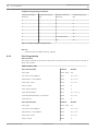
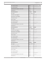
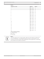
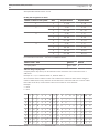
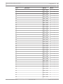
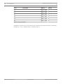
3.3
Installer and User Code Commands
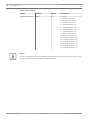
The system supports programmable 4- to 6-digit Installer and User Code to execute the
following programming and operating commands.
The installer commands can be used only when all areas of the system are in disarming status
with no alarm activated and when installer access is enabled from user.
Notice!
No identical User Codes are allowed. User Codes are not permitted to be the same as
Installer codes.
Bosch Sicherheitssysteme GmbH
Quick Start Guide
2013.07 | 03 | F.01U.267.113
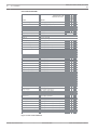
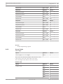
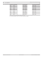
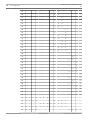
Command
Master User
S w itch to M a in K e yp a d
[C o d e ] + [0 ][0 ][0 ] + [# ] (T e xt K P )
√
√
S w itch to P a rtitio n 0 1 -1 6
[C o d e ] + [0 ][ _ ][ _ ] + [# ] (T e xt K P )
√
√
Basic User
Function
Super User
(Default User Code = 2580
Default Inst. Code = 1234)
Instal. User
User Code Commands
Arming User
AMAX panel 4000 / AMAX panel 4000
EN
en | Installation
Duress User
8
A W A Y a rm
[C o d e ] + [1 ][1 ] + [# ] / [C o d e ] + [# ] / [# ] (Q u ick a rm )
√
√
√
√
√
√
S T A Y a rm
[C o d e ] + [1 ][2 ] + [# ] / [C o d e ] + [*] / [*] (Q u ick a rm )
√
√
√
√
√
√
D isa rm
[C o d e ] + [# ]
√
√
√
√
√
D isp la y In fo (F a u lt/T a m p e r..)
[C o d e ] + [-]
√
√
Keypad Emergency Alarm
Long press [1] and [3] or [*] and [#]
Keypad Fire
Long press [4] and [6]
Keypad Medical Alarm
Long press [7] and [9]
F a u lt/T a m p e r In q u ire
[C o d e ] + [2 ][1 ] + [# ]
√
√
√
Check All Event Log
[C o d e ] + [2 ][2 ] + [# ]
√
√
√
Check EN Event Log
[C o d e ] + [2 ][3 ] + [# ] (T e xt K P )
√
√
√
Check Dialer Event Log
[C o d e ] + [2 ][4 ] + [# ] (T e xt K P )
√
√
√
√
√
√
Zone Bypass/Cancel
√
[Code] + [3][1] + [#] + [Zone No] [*] + [#] (Bypass)
[Code] + [3][1] + [#] + [Zone No] [*] + [#] (Cancel LED)
√
√
√
√
[Code] + [3][2] + [#] + [Zone No] [*] + [#](Cancel Text KP)
√
√
√
√
Bypass Inquire
[Code] + [3][3] + [#] (Text KP)
√
√
√
√
B yp a ss F a u lt/T a m p e r
[C o d e ] + [3 ][4 ] + [# ]
√
√
√
√
S ire n te st
[C o d e ] + [4 ][1 ] + [# ]
√
√
√
C o m m u n ica tio n te st
[C o d e ] + [4 ][2 ] + [# ]
√
√
√
W a lk te st
[C o d e ] + [4 ][3 ] + [# ]
√
√
√
C h a n g e /V ie w d a te /tim e
[C o d e ] + [5 ][1 ] + [# ]
D a ylig h t S a vin g T im e (+ 1 h )
[C o d e ] + [5 ][2 ] + [# ]
√
√
√
√
D a ylig h t S a vin g T im e (-1 h )
[C o d e ] + [5 ][3 ] + [# ]
√
√
√
A d d / D e le te / C h a n g e U se r
[C o d e ] + [5 ][4 ] + [# ]
√
√
C h a n g e In d ivid u a l C o d e
[C o d e ] + [5 ][5 ] + [# ]
C h a n g e D o m e stic P h o n e N o .1
[C o d e ] + [5 ][6 ][# ] + [ _ _ _ _ _ _ ][# ] (L E D K P )
√
C h a n g e D o m e stic P h o n e N o .2
[C o d e ] + [5 ][6 ][# ][# ] + [ _ _ _ _ _ _ ][# ] (L E D K P )
√
C h a n g e D o m e stic P h o n e N o .3
[C o d e ] + [5 ][6 ][# ][# ][# ] + [ _ _ _ _ _ _ ][# ] (L E D K P )
√
C h a n g e D o m e stic P h o n e N o .4
[C o d e ] + [5 ][6 ][# ][# ][# ][# ] + [ _ _ _ _ _ _ ][# ] (L E D K P )
√
C h a n g e D o m e stic P h o n e N o .1 -4
[C o d e ] + [5 ][6 ][# ] + [_ ] + [# ] + [ _ _ _ _ _ _ ][# ] (T e xt K P )
√
C a ll B a ck
[C o d e ] + [5 ][7 ] + [# ]
√
Change Language
[C o d e ] + [5 ][8 ] + [# ] + [ _ ] [_ ] + [# ]
01=EN 02=DE 03=ES 04=FR
0 5 = IT 0 6 = P L 0 7 = N L 0 8 = S E
√
√
√
R e se t ta m p e r o r fa u lt
[C o d e ] + [6 ] + [# ]
√
√
√
Installer Access
[Code] + [7][1] + [#] (Enable)
[Code] + [7][2] + [#] (Disable)
√
√
√
√
√
√
√
S yste m re se t
[C o d e ] + [9 ][9 ][8 ][9 ] + [# ]
In sta lle r p ro g ra m m o d e
[C o d e ] + [9 ][5 ][8 ] + [# ]
√
√
√
E xits P ro g r. m o d e w ith o u t sa ve
[9 ][5 ][9 ] + [# ]
(only in A dres s P rogr. M ode)
√
E xits P ro g r. m o d e w ith sa ve
[9 ][6 ][0 ] + [# ]
(only in A dres s P rogr. M ode)
√
S e t F a cto ry D e fa u lts
[9 ][6 ][1 ] + [# ]
(only in A dres s P rogr. M ode)
√
C o p y co n tro l p a n e l d a ta to p ro g r. K e y
[9 ][6 ][2 ] + [# ]
(only in A dres s P rogr. M ode)
√
C o p y p ro g r. ke y d a ta to co n tro l p a n e l.
[9 ][6 ][3 ] + [# ]
(only in A dres s P rogr. M ode)
√
D isp la y F W ve rsio n
[9 ][9 ][9 ] + [# ]
(only in A dres s P rogr. M ode)
√
√
Figure 3.1: User Code Commands
2013.07 | 03 | F.01U.267.113
Quick Start Guide
Bosch Sicherheitssysteme GmbH
AMAX panel 4000 / AMAX panel 4000
EN
3.4
Installation | en
9
Prerequisites for Certification conform Installation
EN 50131-3 Grade 2, Environmental Class 2
–
System must be placed inside the monitored area on a stable surface.
–
Keypads must be mounted to the inner side of the monitored area.
–
Once the system is tested and ready to use, Enclosure Door and Accessory Enclosures
must be secured with the provided screws
–
To realize EN conform Alarm Indication and Transmission, one of the following options
must be used
–
Two supervised Warning devices (PO-1 PO-2 & PO+) and one ATS 2 Communicator
(onboard Dialer, B426, D4020 or DX4020G)
–
One self powered Warning Device and one ATS 2 Communicator (onboard Dialer,
B426, D4020 or DX4020G)
–
Two Communicators, one ATS 2 (onboard Dialer, B426, D4020 or DX4020G) and one
ATS 1 (onboard Dialer, B426, D4020 or DX4020G)
–
One ATS 3 Communicator (DX4020 or B426)
All Communicators must be connected to a Central Monitoring Station.
Only the onboard Dialer and the Option Bus Communicators can be used for EN Alarm
Transmission.
–
one 12V/7AH or one 12V/18Ah Battery must be connected to the System.
–
max current for all components with a 7Ah Battery = 550mA
max current for all components with a 18Ah Battery = 1500mA
(standby 12h, recharge Battery 80% in 72h)
(PCB=l00mA, IUI-AMAX Keypads=31mA, DX2010=35mA, DX3010=10mA, B426=100mA,
DX4020G=65mA, RF3227E=30mA, RFRC-OPT=30mA)
–
To realize EN conform Arming procedure an indication of arm/disarm status must be
accessible from outside the monitored area (this indication can be time limited)
–
To realize EN conform Access to the Monitored Area, one of the following options must
be used
–
Opening a door (to the entry/exit route) must start the entry procedure
–
Indication of arm/disarm Status
–
Access to the monitored Area (doors not starting entry procedure) is prevented (e.g.
door strike, mechanically)
The Enclosure lock can only be used in non EN setup.
–
Telephone arming can only be used in non EN setup.
–
Accessory Modules, except input module (DX2010) can be used only inside the enclosure
(on the adapter plate).
–
When input module (DX2010) is used in the external enclosure (AE20) the tamper skirt
must be installed on the PCB of input module (DX2010)
–
The panel must be programmed with the EN settings indicated on the programming
sheet. When the panel is set without EN parameters, the EN Indication (on Label) must
be removed.
Bosch Sicherheitssysteme GmbH
Quick Start Guide
2013.07 | 03 | F.01U.267.113
10
AMAX panel 4000 / AMAX panel 4000
EN
en | Configuration
4
Configuration
The control panel programming options are stored in a non-volatile flash memory. This
memory has all relevant configuration and user-specific data even after a total power loss.
Because the data retention time is quite long without power, reprogramming is not required
after powering up the control panel.
Programming with keypad is possible only when all of zones in the system are in disarmed
status and no alarm is activated. Installer Code is required for programming.
Notice!
It is not recommended to use other keypads or methods simultaneously to program the
system while programming with the current keypad.
4.1
Programming with Keypad
4.1.1
LCD Keypad Menu Programming
1.
Enable Text keypad and confirm that the system is in disarmed status.
2.
Enter Installer Code + [958] and press [#] to get to [Installer Menu].
3.
Programming: Select the menu and operate according to the menu prompt.
–
Down to the next menu: Press [▼]
–
Up to the previous menu: Press [▲]
–
Enter menu or confirm input: Press [#]
–
Back to the menu or delete a single input: Press [-]; or press and hold [-] for 3
seconds to end the input state and get back to the menu.
–
Operate according to the menu prompt. Select menu and enter data for specific
programming items according to the display on the keypad to complete
programming, step by step.
–
The data value ranges in the menu programming and address programming are the
same. For specific options and value ranges, see contents in LCD Keypad Menu
Programming, page 10.
4.
After completing input, press [-] to get back to the previous menu. Complete all
programming input by repeating step 3 and press [-] to get back to the current main
menu level by level.
5.
Press [-] to enter menu options. It is optional to save or not to save the programming
information.
6.
Select [Save and Exit] and press [#] to save system programming data, exit menu
programming and reset system.
4.1.2
LED/Icon LCD Keypad Address Programming
1.
Enable LED keypad or Icon LCD keypad and make sure that the system is in disarmed
status.
2.
Enter programming mode: Enter the Installer Code (the default is 1234) + [958] and
press [#].
3.
Programming: Move to the required address and enter the value for each data bit (data
value).
–
After entering programming mode, the system directly enters the programming data
in the address 0000 (Receiver 1 telephone number or the initial digit of the IP
address), then
2013.07 | 03 | F.01U.267.113
Quick Start Guide
Bosch Sicherheitssysteme GmbH
AMAX panel 4000 / AMAX panel 4000
EN
Configuration | en
11
–
Enter the next address: Press [#]
–
Back to the previous address: Press [*]
–
Skip to other address: Enter the address code and press [#]
–
Set new data in the address: Enter new data values and press [*]
–
Enter new data values as required. Otherwise, the factory Default will be used in the
system.
4.
Exit programming mode: Enter Command [9] [6] [0] and press [#] to save programming
data. Entering [9] [5] [9] + [#] means not to save the programming data.
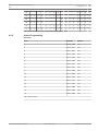
For LED/Icon LCD keypad, the programming data is displayed by the keypad indicator. See
Programming Data Indicators, page 11.
Notice!
For LED/Icon LCD keypad, when the programming data exceeds the display range of the
keypad indicator, there will be no display on the keypad.
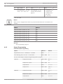
Programming Data Indicators
Data
Value
Zone Indicators
1
2
3
4
5
6
7
8
Mains
0
1
X
2
X
3
X
4
X
5
X
6
X
7
X
8
X
9
X
X
10
X
11
X
X
12
X
X
13
X
X
14
X
X
15
X
X
4.2
Reset to Factory Default Settings
The factory Default can be reset with the ‘Resetting to Factory Default’ pads on the main
board of the control panel.
1.
Disconnect the AC power supply and backup battery to the control panel.
2.
Short-circuit the ‘Resetting to Factory Default’ pads.
3.
These set of pads are located at the top on the printed circuit board of the control panel.
Bosch Sicherheitssysteme GmbH
Quick Start Guide
2013.07 | 03 | F.01U.267.113
12
AMAX panel 4000 / AMAX panel 4000
EN
en | Configuration
4.
Powering up is done when the bonding pads are short-circuited.
5.
Quick flash of the red LED indicator on the printed circuit board of the control panel
indicates that the factory Default will be reset.
6.
All programming parameters are reset to factory default immediately after releasing the
short-circuited bonding pads.
Notice!
If the DEFAULT pads are short-circuited for over 10 seconds after power-up, the control panel
will discard resetting to factory Default.
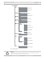
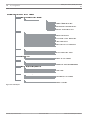
4.3
LCD Menu Programming
For menu programming with LCD keypad, see Section 4.1.1 LCD Keypad Menu Programming
on page 10.
Use [▼] and [▲] to move main menus, submenus and secondary submenus up or down.
Use [-] and [#] to move main menus, submenus and secondary submenus left or right.
2013.07 | 03 | F.01U.267.113
Quick Start Guide
Bosch Sicherheitssysteme GmbH
AMAX panel 4000 / AMAX panel 4000
EN
Configuration | en
13
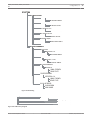
INSTALLER MENU
COM+REPORT SETTING
RECEIVER SETTING
REPORT SETTING
TEST REPORT DURAT.
DUAL IP
REMOTE ACCESS
RPC IP/PORT/DHCP
DOMESTIC/CALLBACK
RING TIMES
CODE SETTING
USER CODE
INSTALLER CODE
CODE LENGTH
CODE PERMISSIONS
ZONE SETTING
ZONE FUNCTION
ADD/DELETE ZONE
PULSE COUNT DURAT.
CROSS TIMER
KP/AREA SETTING
KEYPAD AREA
AREA TIMING
COMMON AREA
KP TONE/LOCKOUT
SYSTEM SETTING
FUNCTION SETTING
DATE/TIME
FAULT CONFIG
QUICK ARM ONLY */#
INSTALLER ACCESS
FORCE ARM FAULT/TA
EVENT RECORD COUNT
LANGUAGE VERSION
KP 2 BUTTON ALARM
SYS TAMPER INDIC.
FACTORY DEFAULT
FUNCTION VIEW
FAULT ANALYSIS
FW VERSION
OUTPUT SETTING
OUTPUT SETTINGS
SIREN SETTINGS
RF SETTING
RF PARA. SETTING
RF RECEIVER
RF SUPERVISION
RF JAM DETECT LEV.
RF LOW BATT REPEAT
SIREN BEEP AR/DIS
RF KEYFOB PANIC AL
RF DEVICE MANAGER
RF REPEATER
RF USER
RF SENSOR DIAGNOSE
RF REPEATER DIAGN.
CLR ALL RF DEVICES
ADDRESS/KEY PROGR
ADDRESS PROGRAM
COPY DATA TO PANEL
COPY DATA TO KEY
Figure 4.1: Menu Structure
Warning!
!
Programming parameters must be set within the value range in the programming address.
Otherwise, the system will turn to indeterminate status.
Bosch Sicherheitssysteme GmbH
Quick Start Guide
2013.07 | 03 | F.01U.267.113
14
AMAX panel 4000 / AMAX panel 4000
EN
en | Configuration
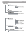
COM+REPORT SETTING
RECEIVER SETTING
INPUT RECEIVER No
PHONE/IP PORT No
SUBSCRIBER ID No
FORMAT
NETWORK ANTIREPLAY
ACK WAIT TIME: sec
NETW. POLLING: min
REPORT SETTING
ZN RESTORE REPORT
AWAY REPORT
STAY REPORT
SYSTEM STAT REPORT
PANIC REPORT
FIRE REPORT
MEDICAL REPORT
AUTOM. TEST REPORT
REPORT EXP. TIME:m
TEST REPORT DURAT.
TEST RPT INTERV: h
TEST REPORT: hour
AUTOM. TEST REPORT
DUAL IP
DUAL IP SETTING
REMOTE ACCESS
REM. ACCESS ARMED
REMOTE PROGRAMMING
RPC IP/PORT/DHCP
IP ADDRESS
PORT No
DHCP UPDATE TIME:h
DOMESTIC/CALLBACK
CALLBACK SETTING
DOMEST/CALLBACK No
RING TIMES
RING COUNT
Figure 4.2: Com+Report
2013.07 | 03 | F.01U.267.113
Quick Start Guide
Bosch Sicherheitssysteme GmbH
AMAX panel 4000 / AMAX panel 4000
EN
Configuration | en
15
CODE SETTING
USER CODE
INPUT USER No
USER CODE PRIORITY
USER CODE IN AREA
CHANGE USER CODE
INSTALLER CODE
CHANGE INST. CODE
CODE LENGTH
CODE LENGTH
CODE PERMISSIONS
TAMPER RESET USER
ARM/DISARM INSTAL.
Figure 4.3: Code Setting
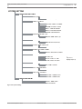
ZONE SETTING
ZONE FUNCTION
ZONE FUNCTION No
ZONE TYPE
FORCE ARM/BYPASS
SILENT AL./CHIME
ZONE PULSE COUNT
ZONE LOCKOUT
ZONE TAMPER
ZONE STATUS REPORT
UNVERF.REP/CROS.ZN
ZONE DOMESTIC
ADD/DELETE ZONE
INPUT ZONE No
ZONE MODULE SEL.
ZONE FUNCTION
ZONE IN AREA
PULSE COUNT DURAT.
PULSE COUNT DURAT.
CROSS TIMER
CROSS ZN TIMER:sec
Figure 4.4: Zone Setting
Bosch Sicherheitssysteme GmbH
Quick Start Guide
2013.07 | 03 | F.01U.267.113
16
AMAX panel 4000 / AMAX panel 4000
EN
en | Configuration
KP/AREA SETTING
KEYPAD AREA
INPUT KEYPAD No
KEYPAD IN AREA
AREA TIMING
INPUT AREA No
EXIT DELAY: sec
ENTRY DELAY: sec
COMMON AREA
COMMON AREA
KP TONE/LOCKOUT
KEYPAD ALARM TONE
KEYPAD LOCK COUNT
Figure 4.5: KP Area Setting
2013.07 | 03 | F.01U.267.113
Quick Start Guide
Bosch Sicherheitssysteme GmbH
AMAX panel 4000 / AMAX panel 4000
EN
Configuration | en
17
SYSTEM SETTING
FUNCTION SETTING
DATE/TIME
CHANGE DATE/TIME
FAULT CONFIG
KEYPAD FAULT SOUND
AC FAULT REP. TIME
DISABLE FAULT REPO
BATT. CHK INTERVAL
PHO. LN SUPERVISED
SIREN SUPERVISED
QUICK ARM ONLY */#
QUICK ARM ONLY */#
INSTALLER ACCESS
INSTALLER ACCESS
FORCE ARM FAULT/TA
FORCE ARM FAULT/TA
EVENT RECORD COUNT
EVENT RECORD COUNT
LANGUAGE VERSION
* 1-EN 6-PL
* 2-DE 4-FR 5-IT 7NL
* 1-EN 3-ES 6-PL 8SE
*
only one is
displayed (P1-3)
KP 2 BUTTON ALARM
KP 2 BUTTON AL
SYS TAMPER INDIC.
SYS TAMP. ALL AR.
FACTORY DEFAULT
DEFAULT PANEL YES
DEFAULT PANEL NO
FUNCTION VIEW
FAULT ANALYSIS
FW VERSION
Figure 4.6: System Setting
Bosch Sicherheitssysteme GmbH
Quick Start Guide
2013.07 | 03 | F.01U.267.113
18
AMAX panel 4000 / AMAX panel 4000
EN
en | Configuration
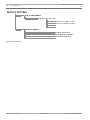
OUTPUT SETTING
OUTPUT SETTINGS
ENTER OUTPUT No
OUTPUT EVENT TYPE
OUTPUT AREA / ZONE
OUTPUT MODE
OUTPUT TIME: sec
SIREN SETTINGS
SIREN TIME: min
SIREN BEEP ENABLE
IN SIREN IND. EN
SIREN OFF ON KEY
Figure 4.7: Output Setting
2013.07 | 03 | F.01U.267.113
Quick Start Guide
Bosch Sicherheitssysteme GmbH
AMAX panel 4000 / AMAX panel 4000
EN
Configuration | en
19
RF SETTING
RF PARA. SETTING
RF RECEIVER
RF RECEIVER ENABLE
RF SUPERVISION
RF DEVICE SUPERV:
RF JAM DETECT LEV.
SIGNAL JAM DETECT:
RF LOW BATT REPEAT
LOW BATT. REPEAT:
SIREN BEEP AR/DIS
REMOTE ARM PROMPT:
RF KEYFOB PANIC AL
RF DEVICE MANAGER
RF REPEATER
REPEATER No: 1-8
REPEATERID: MANUAL
RF USER
KEYFOB No: 1-128
KEYFOB ID: MANUAL
RF SENSOR DIAGNOSE
RF ZONE No:
SIGNAL STRENGTH:
DEVICE STATE:
RF REPEATER DIAGN.
REPEATER No: 1-8
SIGNAL STRENGTH:
DEVICE STATE:
CLR ALL RF DEVICES
CLEAR CONFIRM
CLEAR CANCEL
Figure 4.8: RF Setting
ADDRESS/KEY PROGR
ADDRESS PROGRAM
ADDR[
]VALUE=
COPY DATA TO PANEL
COPY DATA TO KEY
Figure 4.9: Address Key Program
Bosch Sicherheitssysteme GmbH
Quick Start Guide
2013.07 | 03 | F.01U.267.113
20
AMAX panel 4000 / AMAX panel 4000
EN
en | Configuration
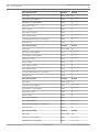
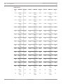
4.4
Address Programming
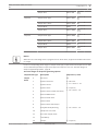
4.4.1
Communication and Report Setting
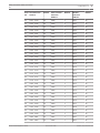
Report Options
Address
Default
Telephone Number / IP Address and Port for Receiver 1
0000 - 0016
15
Subscriber ID Number
0017 - 0022
000000
Transmission Format for Receiver (0 = Not used, 1 =
0023
1
Anti-replay for Receiver (0 = Disabled, 1 = Enabled)
0024
1
Acknowledge Wait Time for Receiver (05 - 99 seconds )
0025 - 0026
05
Network Polling Time for Receiver (001 - 999 minutes )
0027 - 0029
001
Telephone Number / IP Address and Port for Receiver 2
0030 - 0046
15
Subscriber ID Number
0047 - 0052
000000
Transmission Format for Receiver (0 = Not used, 1 =
0053
1
Anti-replay for Receiver (0 = Disabled, 1 = Enabled)
0054
1
Acknowledge Wait Time for Receiver (05 - 99 seconds )
0055 - 0056
05
Network Polling Time for Receive (001 - 999 minutes)
0057 - 0059
001
Telephone Number / IP Address and Port for Receiver 3
0060 - 0076
15
Subscriber ID Number
0077 - 0082
000000
Transmission Format for Receiver (0 = Not used, 1 =
0083
1
Anti-replay for Receiver (0 = Disabled, 1 = Enabled)
0084
1
Acknowledge Wait Time for Receiver (05 - 99 seconds)
0085 - 086
05
Network Polling Time for Receiver (001 - 999 minutes)
0087 - 089
001
Telephone Number / IP Address and Port for Receiver 4
0090 - 0106
15
Subscriber ID Number
0107 - 0112
000000
Transmission Format for Receiver (0 = Not used, 1 =
0113
1
Anti-replay for Receiver (0 = Disabled, 1 = Enabled)
0114
1
Acknowledge Wait Time for Receiver (05 - 99 seconds)
0115 - 0116
05
Network Polling Time for Receiver (001 - 999 minutes)
0117 - 0119
001
Contact ID, 2= SIA, 3 = Conettix IP)
EN=1
Contact ID, 2= SIA, 3 = Conettix IP)
EN=1
Contact ID, 2= SIA, 3 = Conettix IP)
EN=1
Contact ID, 2= SIA, 3 = Conettix IP)
EN=1
2013.07 | 03 | F.01U.267.113
Quick Start Guide
Bosch Sicherheitssysteme GmbH
AMAX panel 4000 / AMAX panel 4000
EN
Configuration | en
21
Notice!
Enter telephone number when the Contact ID or SIA format is selected; enter IP address and
port number when the Bosch Network format is selected. Anti-replay for Receiver,
Acknowledge Wait Time for Receiver and Network Polling Time for Receiver are valid only
when using Bosch Network format.
Setting Telephone Number
For telephone number programming, See Telephone Programming Parameters, page 26
Setting IP Address and Port Number
The IP address is programmed with the 17 digits: Digits 1 - 12 for the IP address of the
receiver; 13 - 17 for the port.
It is not necessary to enter dots in programming, but 0 must be entered ahead of the digit to
make up 3 digits when each IP address unit is fewer than 3 digits. 0 must be entered ahead of
the digit to make up 5 digits when the port is fewer than 5 digits.
Example:
Receiver IP address 128.73.168.7, port 7700, should be made as: 128 073 168 007 07700
Dual IP Settings
Option
Address
Default
0 = 1 IP module, 1 = 2 IP modules
0120
1
Notice!
Dual IP Settings are valid only when used in the Connetix IP format. This programming option
is valid for B426 and ITS-DX4020-G modules. ITS-DX4020-G cannot be set as No. 2 IP module.
Module
Address
ITS-DX4020-G module or B426- module 1
134
B426 module 2
250
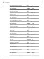
System Reporting
Option
Address
Default
Zone Status Restore Report
0121
6
AWAY Arming / Disarming Report
0122
6 EN=1/5/6/7
STAY Arming / Disarming Report
0123
6 EN=1/5/6/7
System Status Report (Zone fail, comm. fail, telephone
0124
6
Keypad Panic Alarm Report
0125
0
Keypad Fire Alarm Report
0126
0
Keypad Medical Alarm Report
0127
0
EN=1/5/6/7
line fail, AC fail, low batterie...etc.)
Bosch Sicherheitssysteme GmbH
Quick Start Guide
2013.07 | 03 | F.01U.267.113
22
AMAX panel 4000 / AMAX panel 4000
EN
en | Configuration
Automatic Test Report
0128
6
EN=1/5/6/7
0 = No report, 1 = Receiver 1, 2 = Receiver 2, 3 = Receiver 3, 4 = Receiver 4, 5 = Receiver
1,2,3 and 4, 6 = Receiver 1 (2,3 and 4 for backup), 7 = Receiver 1 (2 for backup) and receiver
3 (4 for backup)
Notice!
When the Transmission Format for Receiver in the receiver programming is set to 0 (not
used), i.e., setting the report option as sending report to a receiver, then the alarm control
panel will actually not send any report.
Automatic Test Report
Address 0129 - 0134
Address
Default
Test Report Time: Interval
0129 - 0130
24 VDS-A
00 = Do not use timing report , 01 - 99 = 1 - 99 hours
Report Time: Hour
EN=1=24
0131 - 0132
99
0133 - 0134
99
Address 0135 - 0137
Address
Default
000 = No time limit, 001 - 255 = 1 - 255 minutes
0135 - 0137
000 VDS-A
00 - 23 = 0 - 23 hours, Others = Do not use real-time
report
Report Time: Minute
00 - 59 = 0 - 59 minutes, Others = Do not use real-time
report
Report Expiry Time
EN=000
Installer Access Until Next Arming
Address 0138
Address
Default
0 = disabled, 1 = enabled
0138
0
Address 0139
Address
Default
0 = disabled, 1 = enabled
139
1VDS-A
Address 0140
Address
Default
0 = disabled, 1 = PO1 enabled, 2 = PO2 enabled, 3 =
0140
0 VDS-A
VDS-A=1
Force Arm When System Is In Trouble Condition
EN=0
Siren / PO 1+2 Supervision
EN=3
PO1+2 enabled
2013.07 | 03 | F.01U.267.113
Quick Start Guide
Bosch Sicherheitssysteme GmbH
AMAX panel 4000 / AMAX panel 4000
EN
Configuration | en
23
Keypad 2 Button Alarm
Address 0141
Address
Default
0 = disabled, 1 = enabled
0141
0
Address 0142
Address
Default
0 = disabled, 1 = enabled
0142
0
Address 0143
Address
Default
0 = disabled, 1 = enabled
0143
1
Address 0144
Address
Default
0 = Panel does not answer
0144
14
Address 0145
Address
Default
0 = disabled, 1 = enabled
0145
1 VDS-A=0
Address 0146 - 0161
Address
Default
See Telephone Programming Parameters, page 26
0146 - 0161
15
Address 0162 - 0179
Address
Default
RPC IP No
0162 - 0173
15
RPC Port Number
0174 - 0178
15
Control Panel DHCP Update Time (hours)
0179
15
Phone Line Monitor
VDS-A EN=1
Beep For Warning Devices
Ring Count
1 - 13 = Number of rings until the control panel responds
14 = Call the control panel and allow the phone to ring no
more than twice and hang up. Wait a minimum of 8 sec
and call the control panel again. The control panel
answers on the first ring.
15 = Call the control panel and allow the phone to ring no
more than four times and then hang up. If you call again
within 45 sec, the control panel answers the call on the
first ring.
Remote Programming
Callback Telephone Number
Remote PC Setting
RPC is the remote programming computer equipped with remote programming software.
Bosch Sicherheitssysteme GmbH
Quick Start Guide
2013.07 | 03 | F.01U.267.113
24
AMAX panel 4000 / AMAX panel 4000
EN
en | Configuration
Remote Access To Panel When Panel Is Armed
Address 0180
Address
Default
0 = Disable, 1 = Enable ; Default 1
0180
1
Address 0181
Address
Default
0 = Default, 1 = EN, 2 = DE, 3 = ES, 4 = FR, 5 = IT, 6 = PL,
0181
0
Address 0182
Address
Default
0 = Disable, 1 = Enable
0182
1
Address 0183
Address
Default
0 = Disable, 1 = Enable
0183
0
Address 0184
Address
Default
0 = Disable, 1 = Enable
0184
1
Keypad Language
7 = NL, 8 = SE
Tamper Reset For User
Arm / Disarm For Installer
Zone Tamper Bypass when DEOL Zone is Bypassed
0=Incert
–
This function is only accessible in address programming
Call Back Setting
Address 0196
Address
Default
0 = Disable, 1 = Enable
0196
0
Address 0197
Address
Default
0 = Disable, 1 = Enable
0197
1
Address 0198 - 0200
Address
Default
0 = Disable, 1-999sec = Duration
0198 - 200
060
Silence Warning Device On Disarm
Zone Pulse Count Duration
VDS-A
EN=000
2013.07 | 03 | F.01U.267.113
Quick Start Guide
Bosch Sicherheitssysteme GmbH
AMAX panel 4000 / AMAX panel 4000
EN
Configuration | en
25
Event Record Count per Set/Unset Period
Address 0201
Address
Default
3 - 10
0201
10
Address 0202
Address
Default
0 = Area 1, 1 = All Areas
0202
0
Address 0203
Address
Default
0=Disable, 1=enabled
0203
0
Address 0204
Address
Default
0 = Disabled , 1-15 minutes
0204
15VDS-A
EN=10
System Tamper Indication In Area
Internal Siren Beep As Indication
Battery Check Interval
EN=15
Cross Zone Timer
Address 0205 - 0207
Address
Default
001 - 999 seconds
0205 - 0207
060
Address 0208 - 0209
Address
Default
99 = Disabled, 00 - 98 minutes
0208 - 0209
60
AC Power Supply Fault Report Delay
VDS-A
EN=00-60
Domestic Call Telephone Number
Address 1618 - 1682
Address
Default
Domestic Call Telephone Number 1
1618 - 1633
15
Domestic Call Telephone Number 2
1634 - 1649
15
Domestic Call Telephone Number 3
1650 - 1665
15
Domestic Call Telephone Number 4
1666 - 1681
15
See Telephone Programming Parameters, page 26
If the default 15 is set to the initial digit of the telephone number, domestic telephone alarm
function is disabled; If set to other positions, it marks the end of the telephone number.
Bosch Sicherheitssysteme GmbH
Quick Start Guide
2013.07 | 03 | F.01U.267.113
26
AMAX panel 4000 / AMAX panel 4000
EN
en | Configuration
Telephone Programming Parameters
Telephone Number
Programming Input
Telephone Number
Programming Input
Required
Key
Required
Key
0
0
7
7
1
1
8
8
2
2
9
9
3
3
*
11
4
4
#
12
5
5
4 seconds pause
13
6
6
15
15
Table 4.1: Telephone Programming Parameters
See also
–
4.4.2
Communication and Report Setting , page 26
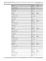
Zone Programming
Zone Functions
The system supports up to 64 zones. Each zone can select one of 16 zone functions as well as
Areas and modules.
Address 0210 - 0361
Zone Function # 00
Address
Default
Zone Type
0210 - 0211
00
Force Arm / Zone Bypass
0212
3
VDS-A EN=0/2
Silent Alarm / Chime Mode
0213
0
VDS-A EN=0/2
Zone Pulse Count
0214
0
VDS-A EN=0
Zone Lockout
0215
3
Zone Tamper (DEOL)
0216
1
Zone Status Report
0217
6
VDS-A EN=1/5/6/7
Unverified Alarm Report / Cross Zone
0218
0
VDS-A EN=0
Domestic No.
0219
0
Zone Function # 01
Address
Default
Zone Type
0220 - 0221
01
Force Arm / Zone Bypass
0222
3
VDS-A EN=0/2
Silent Alarm / Chime Mode
0223
0
VDS-A EN=0/2
Zone Pulse Count
0224
0
VDS-A EN=0
Zone Lockout
0225
3
2013.07 | 03 | F.01U.267.113
Quick Start Guide
Bosch Sicherheitssysteme GmbH
AMAX panel 4000 / AMAX panel 4000
EN
Configuration | en
Zone Tamper (DEOL)
0226
1
Zone Status Report
0227
6
VDS-A EN=1/5/6/7
Unverified Alarm Report / Cross Zone
0228
0
VDS-A EN=0
Domestic No.
0229
0
Zone Function # 02
Address
Default
Zone Type
0230 - 0231
02
Force Arm / Zone Bypass
0232
3
VDS-A EN=0/2
Silent Alarm / Chime Mode
0233
0
VDS-A EN=0/2
Zone Pulse Count
0234
0
VDS-A EN=0
Zone Lockout
0235
3
Zone Tamper (DEOL)
0236
1
Zone Status Report
0237
6
VDS-A EN=1/5/6/7
Unverified Alarm Report / Cross Zone
0238
0
VDS-A EN=0
Domestic No.
0239
0
Zone Function # 03
Address
Default
Zone Type
0240 - 0241
03
Force Arm / Zone Bypass
0242
3
VDS-A EN=0/2
Silent Alarm / Chime Mode
0243
0
VDS-A EN=0/2
Zone Pulse Count
0244
0
VDS-A EN=0
Zone Lockout
0245
3
Zone Tamper (DEOL)
0246
1
Zone Status Report
0247
6
VDS-A EN=1/5/6/7
Unverified Alarm Report / Cross Zone
0248
0
VDS-A EN=0
Domestic No.
0249
0
Zone Function # 04
Address
Default
Zone Type
0250 - 0251
04
Force Arm / Zone Bypass
0252
3
VDS-A EN=0/2
Silent Alarm / Chime Mode
0253
0
VDS-A EN=0/2
Zone Pulse Count
0254
0
VDS-A EN=0
Zone Lockout
0255
3
Zone Tamper (DEOL)
0256
1
Zone Status Report
0257
6
VDS-A EN=1/5/6/7
Unverified Alarm Report / Cross Zone
0258
0
VDS-A EN=0
Domestic No.
0259
0
Bosch Sicherheitssysteme GmbH
Quick Start Guide
27
2013.07 | 03 | F.01U.267.113
28
AMAX panel 4000 / AMAX panel 4000
EN
en | Configuration
Zone Function # 05
Address
Default
Zone Type
0260 - 0261
05
Force Arm / Zone Bypass
0262
3
VDS-A EN=0/2
Silent Alarm / Chime Mode
0263
0
VDS-A EN=0/2
Zone Pulse Count
0264
0
VDS-A EN=0
Zone Lockout
0265
3
Zone Tamper (DEOL)
0266
1
Zone Status Report
0267
6
VDS-A EN=1/5/6/7
Unverified Alarm Report / Cross Zone
0268
0
VDS-A EN=0
Domestic No.
0269
0
Zone Function # 06
Address
Default
Zone Type
0270 - 0271
06
Force Arm / Zone Bypass
0272
3
VDS-A EN=0/2
Silent Alarm / Chime Mode
0273
0
VDS-A EN=0/2
Zone Pulse Count
0274
0
VDS-A EN=0
Zone Lockout
0275
3
Zone Tamper (DEOL)
0276
1
Zone Status Report
0277
6
VDS-A EN=1/5/6/7
Unverified Alarm Report / Cross Zone
0278
0
VDS-A EN=0
Domestic No.
0279
0
Zone Function # 07
Address
Default
Zone Type
0280 - 0281
07
Force Arm / Zone Bypass
0282
3
VDS-A EN=0/2
Silent Alarm / Chime Mode
0283
0
VDS-A EN=0/2
Zone Pulse Count
0284
0
VDS-A EN=0
Zone Lockout
0285
3
Zone Tamper (DEOL)
0286
1
Zone Status Report
0287
6
VDS-A EN=1/5/6/7
Unverified Alarm Report / Cross Zone
0288
0
VDS-A EN=0
Domestic No.
0289
0
Zone Function # 08
Address
Default
Zone Type
0290 - 0291
08
Force Arm / Zone Bypass
0292
3
VDS-A EN=0/2
Silent Alarm / Chime Mode
0293
0
VDS-A EN=0/2
2013.07 | 03 | F.01U.267.113
Quick Start Guide
Bosch Sicherheitssysteme GmbH
AMAX panel 4000 / AMAX panel 4000
EN
Configuration | en
Zone Pulse Count
0294
0
Zone Lockout
0295
3
Zone Tamper (DEOL)
0296
1
Zone Status Report
0297
6
VDS-A EN=1/5/6/7
Unverified Alarm Report / Cross Zone
0298
0
VDS-A EN=0
Domestic No.
0299
0
Zone Function # 09
Address
Default
Zone Type
0300 - 0301
09
Force Arm / Zone Bypass
0302
3
VDS-A EN=0/2
Silent Alarm / Chime Mode
0303
0
VDS-A EN=0/2
Zone Pulse Count
0304
0
VDS-A EN=0
Zone Lockout
0305
3
Zone Tamper (DEOL)
0306
1
Zone Status Report
0307
6
VDS-A EN=1/5/6/7
Unverified Alarm Report / Cross Zone
0308
0
VDS-A EN=0
Domestic No.
0309
0
Zone Function # 10
Address
Default
Zone Type
0310 - 0311
10
Force Arm / Zone Bypass
0312
3
VDS-A EN=0/2
Silent Alarm / Chime Mode
0313
0
VDS-A EN=0/2
Zone Pulse Count
0314
0
VDS-A EN=0
Zone Lockout
0315
3
Zone Tamper (DEOL)
0316
1
Zone Status Report
0317
6
VDS-A EN=1/5/6/7
Unverified Alarm Report / Cross Zone
0318
0
VDS-A EN=0
Domestic No.
0319
0
Zone Function # 11
Address
Default
Zone Type
0320 - 0321
11
Force Arm / Zone Bypass
0322
3
VDS-A EN=0/2
Silent Alarm / Chime Mode
0323
0
VDS-A EN=0/2
Zone Pulse Count
0324
0
VDS-A EN=0
Zone Lockout
0325
3
Zone Tamper (DEOL)
0326
1
Zone Status Report
0327
6
Bosch Sicherheitssysteme GmbH
Quick Start Guide
VDS-A EN=0
VDS-A EN=1/5/6/7
29
2013.07 | 03 | F.01U.267.113
30
AMAX panel 4000 / AMAX panel 4000
EN
en | Configuration
Unverified Alarm Report / Cross Zone
0328
0
Domestic No.
0329
0
Zone Function # 12
Address
Default
Zone Type
0330 - 0331
12
Force Arm / Zone Bypass
0332
3
VDS-A EN=0/2
Silent Alarm / Chime Mode
0333
0
VDS-A EN=0/2
Zone Pulse Count
0334
0
VDS-A EN=0
Zone Lockout
0335
3
Zone Tamper (DEOL)
0336
1
Zone Status Report
0337
6
VDS-A EN=1/5/6/7
Unverified Alarm Report / Cross Zone
0338
0
VDS-A EN=0
Domestic No.
0339
0
Zone Function # 13
Address
Default
Zone Type
0340 - 0341
13
Force Arm / Zone Bypass
0342
3
VDS-A EN=0/2
Silent Alarm / Chime Mode
0343
0
VDS-A EN=0/2
Zone Pulse Count
0344
0
VDS-A EN=0
Zone Lockout
0345
3
Zone Tamper (DEOL)
0346
1
Zone Status Report
0347
6
VDS-A EN=1/5/6/7
Unverified Alarm Report / Cross Zone
0348
0
VDS-A EN=0
Domestic No.
0349
0
Zone Function # 14
Address
Default
Zone Type
0350 - 0351
14
Force Arm / Zone Bypass
0352
3
VDS-A EN=0/2
Silent Alarm / Chime Mode
0353
0
VDS-A EN=0/2
Zone Pulse Count
0354
0
VDS-A EN=0
Zone Lockout
0355
3
Zone Tamper (DEOL)
0356
1
Zone Status Report
0357
6
VDS-A EN=1/5/6/7
Unverified Alarm Report / Cross Zone
0358
0
VDS-A EN=0
Domestic No.
0359
0
Zone Function # 15
Address
Default
Zone Type
0360 - 0361
15
2013.07 | 03 | F.01U.267.113
Quick Start Guide
VDS-A EN=0
Bosch Sicherheitssysteme GmbH
AMAX panel 4000 / AMAX panel 4000
EN
Configuration | en
Force Arm / Zone Bypass
0362
3
VDS-A EN=0/2
Silent Alarm / Chime Mode
0363
0
VDS-A EN=0/2
Zone Pulse Count
0364
0
VDS-A EN=0
Zone Lockout
0365
3
Zone Tamper (DEOL)
0366
1
Zone Status Report
0367
6
VDS-A EN=1/5/6/7
Unverified Alarm Report / Cross Zone
0368
0
VDS-A EN=0
Domestic No.
0369
0
31
For the value range of each zone function option, See Zone Functions, page 26
Zone Function Option
Zone Function Option
Zone Type
Bosch Sicherheitssysteme GmbH
Description
00
Zone Not Used
01
Instant
02
Interior Instant
03
Delay
04
Interior Delay
05
Follower
06
Interior Follower
07
24-Hour
08
Key-Switch Toggle
09
Key Switch on/off
10
24 Hour Panic
11
24 Hour Fire
12
24 Hour Fire With Verification
13
Tamper
14
Bolt Contact
15
External Fault
16
Delay Exit
17
Interior Delay Exit
18
Technical Alarm
19
Reset
20
Instant Report
21
Reserved
Quick Start Guide
2013.07 | 03 | F.01U.267.113
32
AMAX panel 4000 / AMAX panel 4000
EN
en | Configuration
Force Arm / Bypass
0
Disabled
1
Force Arm
2
Bypass
3
All
0
Disabled
1
Silent Alarm
2
Chime Mode
3
All
Zone Pulse count
0
Disabled
1-9
1-9 Pulses
Zone Lockout
0
Disabled
1
1 Times Alarm Lockout
2
3 Times Alarm Lockout
3
6 Times Alarm Lockout
4
Alarm Duration
0
Disabled
1
Enabled
0
No Report Required
1
Receiver 1
2
Receiver 2
3
Receiver 3
4
Receiver 4
5
Receiver 1, 2, 3 and 4
6
Receiver 1 (2, 3 and 4 for backup)
7
Receiver 1 (2 for backup) and Receiver 3 (4 for backup)
0
Disabled
1
Unverified Alarm Report
2
Cross Zone
3
All
Follow 'Alarm report' Option's Logic. Range 0-7
0
No Reports Allowed
1
Report to Destination 1
2
Report to Destination 2
3
Report to Destination 3
Silent Alarm / Chime
Mode
Zone Tamper (DEOL)
Zone Status Report
Unverified Alarm
Report / Cross Zone
Domestic Call
2013.07 | 03 | F.01U.267.113
Quick Start Guide
Bosch Sicherheitssysteme GmbH
AMAX panel 4000 / AMAX panel 4000
EN
Configuration | en
Report to Destination 4
5
Report to Destination 1 ,2, 3, 4
6
Report to Destination 1 (2, 3, 4 backup)
7
Report to Destination 1 (2 Backup) and 3 (4 backup)
4
33
Bosch Sicherheitssysteme GmbH
Quick Start Guide
2013.07 | 03 | F.01U.267.113
34
AMAX panel 4000 / AMAX panel 4000
EN
en | Configuration
Common Area Settings
Option
Address
Default
Value Range
Common Area Type
0370
0
0 = none
1 = Follow Partition 2
2 = Follow Partition 2-3
3 = Follow Partition 2-4
4 = Follow Partition 2-5
5 = Follow Partition 2-6
6 = Follow Partition 2-7
7 = Follow Partition 2-8
8 = Follow Partition 2-9
9 = Follow Partition 2-10
10 = Follow Partition 2-11
11 = Follow Partition 2-12
12 = Follow Partition 2-13
13 = Follow Partition 2-14
14 = Follow Partition 2-15
15 = Follow Partition 2-16
Notice!
In case of common Area, the Area 1 will be the common Area. When there is only 1 Area in the
system, the address 0370 can only be programmed as 1.
2013.07 | 03 | F.01U.267.113
Quick Start Guide
Bosch Sicherheitssysteme GmbH
AMAX panel 4000 / AMAX panel 4000
EN
Configuration | en
35
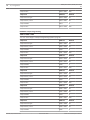
Zone Area, Zone Functions and Module Selection
Zone Area Selection
No
Default
Address
Zone Function
Default
Module
Selection
Selection
Address
Address
Default
1
0678 - 0679
01
0806
3
0870
0
2
0680 - 0681
01
0807
1
0871
0
3
0682 - 0683
01
0808
1
0872
0
4
0684 - 0685
01
0809
1
0873
0
5
0686 - 0687
01
0810
1
0874
0
6
0688 - 0689
01
0811
1
0875
0
7
0690 - 0691
01
0812
1
0876
0
8
0692 - 0693
01
0813
1
0877
0
9
0694 - 0695
01
0814
0
0878
0
10
0696 - 0697
01
0815
0
0879
0
11
0698 - 0699
01
0816
0
0880
0
12
0700 - 0701
01
0817
0
0881
0
13
0702 - 0703
01
0818
0
0882
0
14
0704 - 0705
01
0819
0
0883
0
15
0706 - 0707
01
0820
0
0884
0
16
0708 - 0709
01
0821
0
0885
0
Value Range:
Value Range:0 –15. See
0 = On-board zone,
00 = zone not used,
Section Zone Functions,
1 = Keypad zone
1 - 16 = Area 1- 16
page 26
2 = DX2010 zone
3 = RF Device
15 = not used
Notice!
Zones may be indicated on keypads with a number that are different from zone number used
for programming and hardware input.
Example:
In a one area system keypad zone number 17 should be indicated as Zone number 16 (e.g.
visible on 16 zone LED keypad). After disabling zone 16 * (or another one in range 1 to 16)
zone number 17 is indicated on keypad as number 16.
* change Area Selection to 00 = zone not used.
For more information, also for multi area system refer to AMAX panel 4000 Installation Manual.
Notice!
When a zone is assigned to RF Device (3), then the dedicated On-board zone is not available.
Bosch Sicherheitssysteme GmbH
Quick Start Guide
2013.07 | 03 | F.01U.267.113
36
AMAX panel 4000 / AMAX panel 4000
EN
en | Configuration
Zone Area Selection
No
Default
Address
Zone Function
Default
Module
Selection
Selection
Address
Address
Default
17
0710 - 0711
00
822
1
886
15
18
0712 - 0713
00
823
1
887
15
19
0714 - 0715
00
824
1
888
15
20
0716 - 0717
00
825
1
889
15
21
0718 - 0719
00
826
1
890
15
22
0720 - 0721
00
827
1
891
15
23
0722 - 0723
00
828
1
892
15
24
0724 - 0725
00
829
1
893
15
25
0726 - 0727
00
830
1
894
15
26
0728 - 0729
00
831
1
895
15
27
0730 - 0731
00
832
1
896
15
28
0732 - 0733
00
833
1
897
15
29
0734 - 0735
00
834
1
898
15
30
0736 - 0737
00
835
1
899
15
31
0738 - 0739
00
836
1
900
15
32
0740-0741
00
837
1
901
15
Value Range:
Value Range:0 –15. See
0 = On-Board zone
00 = zone not used,
Section Zone Functions,
1 = Keypad Zone*
1 - 16 = Area 1- 16
page 26
2 = DX2010 Zone**
3 = RF Device
15 = not used
* Zones 17 to 32 are dedicated to Keypad 1 to 32 (Zone 17 = Keypad 1, Zone 32 = Keypad 32)
** Zones 17 to 24 are dedicated to DX2010 address 103 ports 1 to 8, also see Table DX2010
modules
Zones 25 to 32 are dedicated to DX2010 address 104 ports 1 to 8, also see Table DX2010
modules
Notice!
When a zone is assigned to Keypad Zone (1) or RF Device (3), then the dedicated zone on
DX2010 is not available.
2013.07 | 03 | F.01U.267.113
Quick Start Guide
Bosch Sicherheitssysteme GmbH
AMAX panel 4000 / AMAX panel 4000
EN
Zone Area Selection
No
Configuration | en
Default
Address
Zone Function
Default
Module
Selection
Selection
Address
Address
Default
33
0742 - 0743
00
0838
1
0901
15
34
0744 - 0745
00
0839
1
0902
15
35
0746 - 0747
00
0840
1
0903
15
36
0748 - 0749
00
0841
1
0904
15
37
0750 - 0751
00
0842
1
0905
15
38
0752 - 0753
00
0843
1
0906
15
39
0754 - 0755
00
0844
1
0907
15
40
0756 - 0757
00
0845
1
0908
15
41
0758 - 0759
00
0846
1
0909
15
42
0760 - 0761
00
0847
1
0910
15
43
0762 - 0763
00
0848
1
0911
15
44
0764 - 0765
00
0849
1
0912
15
45
0766 - 0767
00
0850
1
0913
15
46
0768 - 0769
00
0851
1
0915
15
47
0770 - 0771
00
0852
1
0916
15
48
0772 - 0773
00
0853
1
0917
15
49
0774 - 0775
00
0854
1
0918
15
50
0776 - 0777
00
0855
1
0919
15
51
0778 - 0779
00
0856
1
0920
15
52
0780 - 0781
00
0857
1
0921
15
53
0782 - 0783
00
0858
1
0922
15
54
0784 - 0785
00
0859
1
0923
15
55
0786 - 0787
00
0860
1
0924
15
56
0788 - 0789
00
0861
1
0925
15
57
0790 - 0791
00
0862
1
0926
15
58
0792 - 0793
00
0863
1
0927
15
59
0794 - 0795
00
0864
1
0928
15
60
0796 - 0797
00
0865
1
0929
15
61
0798 - 0799
00
0866
1
0930
15
62
0800 - 0801
00
0867
1
0931
15
63
0802 - 0803
00
0868
1
0932
15
Bosch Sicherheitssysteme GmbH
Quick Start Guide
37
2013.07 | 03 | F.01U.267.113
38
AMAX panel 4000 / AMAX panel 4000
EN
en | Configuration
64
0804 - 0805
00
0869
1
0933
15
Value Range: 00 = zone not
Value Range:0–15. See
0 = On-Board zone
used, 1 - 16 = Area 1- 16
Section Zone Functions,
1 = Keypad zone
page 26.
2 = DX2010 Zone*
3 = RF Device
15 = not used
* See next table
Notice!
When a zone is assigned to RF Device (3), then the dedicated zone on DX2010 is not
available.
Module
Address
DX2010 module 1 (zones 17 - 24)
103
DX2010 module 2 (zones 25 - 32)
104
DX2010 module 3 (zones 33 - 40)
105
DX2010 module 4 (zones 41 - 48)
106
DX2010 module 5 (zones 49 - 56)
107
DX2010 module 6 (zones 57 - 64)
108
See also
–
4.4.3
Zone Programming, page 26
Output Programming
On-board Output Programming
Option
Address
Default
Keypad Alarm Tone, 0 = Disabled, 1 = Enabled
0503
1
Siren Running Time, 00 - 99 = 0 - 99 minutes
0508 - 0509
00
See The Value Ranges of Output Programming Options, page 39
Output 1
Output Event Type
0510 - 0511
05
VDS-A
EN=5
Output Area / Zone
0512 - 0513
00
Output Mode
0514
0
Output Time
0515 - 0517
VDS-A EN=0
180
VDS-A
EN=180
Output 2
Output Event Type
0518 - 0519
05
VDS-A
EN=5
2013.07 | 03 | F.01U.267.113
Output Area / Zone
0520 - 0521
00
Output Mode
0522
0
Quick Start Guide
VDS-A EN=0
Bosch Sicherheitssysteme GmbH
AMAX panel 4000 / AMAX panel 4000
EN
Configuration | en
Output Time
0523 - 525
000
VDS-A
39
EN=180
Output 3
Output Event Type
0526 - 0527
05
VDS-A
EN=5
Output Area / Zone
0528 - 0529
00
Output Mode
0530
0
Output Time
0531 - 0533
VDS-A EN=0
180
VDS-A
EN=180
Output 4
Output Event Type
0534 - 0535
07
VDS-A
EN=5
Output Area / Zone
0536 - 0537
00
Output Mode
0538
0
Output Time
0539 - 0541
180
VDS-A EN=0
VDS-A
EN=180
Notice!
When the zone activating alarm is programmed as silent alarm, keypad and audible alarm have
no output.
For the corresponding value ranges of output event type, output mode and output time as well
as the relationship between output event type and Output in area see The Value Ranges of
Output Programming Options, page 39
The Value Ranges of Output Programming Options
Output Event Type
Description
Output Area / Zone
Output
0
Not Used
No
1
System Disarmed
0 = All Areas
2
System Armed
3
System Alarm
4
System Alarm (audile and silent)
5
External AWAY Siren
6
External STAY Siren
7
Internal Siren
8
Internal Siren with tamper
9
Entry/Exit Delay Warning
1 - 16 = Areas 1 - 16
10
Telephone Line Fault
11
AC Power Supply Fault
12
Low Battery
13
Tamper
Event
Bosch Sicherheitssysteme GmbH
Quick Start Guide
1 – 16 = Areas 1 - 16
0 = Any Area,
1 - 16 = Areas 1 - 16
0 = Any Area,
2013.07 | 03 | F.01U.267.113
40
AMAX panel 4000 / AMAX panel 4000
EN
en | Configuration
14
External Fault
1 - 16 = Areas 1 - 16
15
All Faults
16
Fire Alarm
0 = Any Area,
17
Fire Reset
18
AWAY Armed
19
STAY Armed
20
Reset *1
1 - 16 = Areas 1 - 16
0 = All Areas
1 - 16 = Areas 1 - 16
0 = Any Area
1 - 16 = Area number
21
Follow Zone Event (Alarm and
Zone Number 1 - 64
tamper)
22
RF Keyfob button 3 (Garage Door)
23
RF Keyfob button 4 (light)
24
Chime Indication *1
25
Verfied Alarm
26
Unverfied Alarm
27
Technical Alarm
28
Bypassed Zone
29
Ready to Arm
0 = All Areas 1 - 16 = Areas 1 - 16
30
Walktest
0
Continuous output
1
Pulse
2
Inverted
Output
000 -
0 - 999 seconds
Time
999
Output
Mode
0 = Any Area,
1 - 16 = Areas 1 - 16
*1 Output Timer is fix. (1 sec)
DX3010 Output Programming
This section is optional programming.
Module
Address
DX3010 module 1 (Output 5 - 12)
150
DX3010 module 2 (Output 13 - 20)
151
Table 4.2: DX3010 Address Settings
DX3010 1 Output Programming
Address 0542 - 0605
See The Value Ranges of Output Programming Options, page 39
2013.07 | 03 | F.01U.267.113
Quick Start Guide
Bosch Sicherheitssysteme GmbH
AMAX panel 4000 / AMAX panel 4000
EN
Configuration | en
Output 5
Address
Default
Output Event Type
0542 - 0543
00
Output Area / Zone
0544 - 0545
00
Output Mode
0546
0
Output Time
0547 - 0549
000
Output 6
Address
Default
Output Event Type
0550 - 0551
00
Output Area / Zone
0552 - 0553
00
Output Mode
0554
0
Output Time
0555 - 0557
000
Output 7
Address
Default
Output Event Type
0558 - 0559
00
Output Area / Zone
0560 - 0561
00
Output Mode
0562
0
Output Time
0563 - 0565
000
Output 8
Address
Default
Output Event Type
0566 - 0567
00
Output Area / Zone
0568 - 0569
00
Output Mode
0570
0
Output Time
0571 - 0573
000
Output 9
Address
Default
Output Event Type
0574 - 0575
00
Output Area / Zone
0576 - 0577
00
Output Mode
0578
0
Output Time
0579 - 0581
000
Output 10
Address
Default
Output Event Type
0582 - 0583
00
Output Area / Zone
0584 - 0585
00
Output Mode
0586
0
Output Time
0587 - 0589
000
Output 11
Address
Default
Output Event Type
0590 - 0591
00
Output Area / Zone
0592 - 0593
00
Output Mode
0594
0
Bosch Sicherheitssysteme GmbH
Quick Start Guide
41
2013.07 | 03 | F.01U.267.113
42
AMAX panel 4000 / AMAX panel 4000
EN
en | Configuration
Output Time
0595 - 0597
000
Output 12
Address
Default
Output Event Type
0598 - 0599
00
Output Area / Zone
0600 - 0601
00
Output Mode
0602
0
Output Time
0603 - 0605
000
DX3010 2 Output Programming
Address 0606 - 0669
See The Value Ranges of Output Programming Options, page 39
Output 13
Address
Default
Output Event Type
0606 - 0607
00
Output Area / Zone
0608 - 0609
00
Output Mode
0610
0
Output Time
0611 - 0613
000
Output 14
Address
Default
Output Event Type
0614 - 0615
00
Output Area / Zone
0616 - 0617
00
Output Mode
0618
0
Output Time
0619 - 0621
000
Output 15
Address
Default
Output Event Type
0622 - 0623
00
Output Area / Zone
0624 - 0625
00
Output Mode
0626
0
Output Time
0627 - 0629
000
Output 16
Address
Default
Output Event Type
0630 - 0631
00
Output Area / Zone
0632 - 0633
00
Output Mode
0634
0
Output Time
0635 - 0637
000
Output 17
Address
Default
Output Event Type
0638 - 0639
00
Output Area / Zone
0640 - 0641
00
Output Mode
0642
0
2013.07 | 03 | F.01U.267.113
Quick Start Guide
Bosch Sicherheitssysteme GmbH
AMAX panel 4000 / AMAX panel 4000
EN
Configuration | en
Output Time
0643 - 0645
000
Output 18
Address
Default
Output Event Type
0646 - 0647
00
Output Area / Zone
0648 - 0649
00
Output Mode
0650
0
Output Time
0651 - 0653
000
Output 19
Address
Default
Output Event Type
0654 - 0655
00
Output Area / Zone
0656 - 0657
00
Output Mode
0658
0
Output Time
0659 - 0661
000
Output 20
Address
Default
Output Event Type
0662 - 0663
00
Output Area / Zone
0664 - 0665
00
Output Mode
0666
0
Output Time
0667 - 0669
000
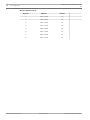
Option
Address
Default
Code Length,4 – 6 = 4 - 6 digits
1003
4
Option
Address
Default
Installer Code
1004
1
1005
2
1006
3
1007
4
1008
5
1009
6
43
See also
–
4.4.4
Output Programming, page 39
Access Codes
Code Length
The access code includes installer Code and User codes.
If the code is set as "15", then code is not used.
The code length is the same for all Access Codes.
Installer Code
Bosch Sicherheitssysteme GmbH
Quick Start Guide
2013.07 | 03 | F.01U.267.113
44
AMAX panel 4000 / AMAX panel 4000
EN
en | Configuration
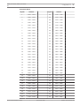
User Codes
User
User
Default/ Value
Area
Default /
User Code
No.
Authority
Range *
Selection
Value Range
Address
Default: 00
1013
2
1014
5
1015
8
1016
0
1017
0
1018
0
1022 - 1027
1031 - 1036
1040 - 1045
1049 - 1054
3= Arming code 1056 - 1057
1058 - 1063
1067 - 1072
1076 - 1081
Level
Default
Address
Address
# 01
1010
Default: 0
1011 - 1012
(master
# 01 master
Value Range:
code)
code
See Table 6.5
Priority is
on page 26.
always 0
#02
1019
Default: 15 *
1020 - 1021
1020 = 1
#03
1028
#04
1037
#05
1046
#06
1055
#07
1064
#08
1073
4= Duress code 1065 - 1066
5-15= No
1074 - 1075
Priority
#09
1082
1083 - 1084
1085 - 1090
#10
1091
1092 - 1093
1094 - 1099
#11
1100
1101 - 1102
1103 - 1108
#12
1109
1110 - 1111
1112 - 1117
#13
1118
1119 - 1120
1121 - 1126
#14
1127
1128 - 1129
1130 - 1135
#15
1136
1137 - 1138
1139 - 1144
#16
1145
1146 - 1147
1148 - 1153
#17
1154
1155 - 1156
1157 - 1162
#18
1163
1164 - 1165
1166 - 1171
#19
1172
1173 - 1174
1175 - 1180
#20
1181
1182 - 1183
1184 - 1189
#21
1190
1191 - 1192
1193 - 1198
#22
1199
1200 - 1201
1202 - 1207
#23
1208
1209 - 1210
1211 - 1216
2013.07 | 03 | F.01U.267.113
Value Range:
1029 - 1030
Default: 15
0= Master code 1038 - 1039
1= Super code:
2= Basic code
1047 -1048
Quick Start Guide
1021 = 5
Bosch Sicherheitssysteme GmbH
AMAX panel 4000 / AMAX panel 4000
EN
Configuration | en
#24
1217
1218 - 1219
1220 - 1225
#25
1226
1227 - 1228
1229 - 1234
#26
1235
1236 - 1237
1238 - 1243
#27
1244
1254 - 1246
1247 - 1252
#28
1253
1254 - 1255
1256 - 1261
#29
1262
1263 - 1264
1265 - 1270
#30
1271
1272 - 1273
1274 - 1279
#31
1280
1281 - 1282
1283 - 1288
#32
1289
1290 - 1291
1292 - 1297
#33
1298
1299 - 1300
1301 - 1306
#34
1307
1308 - 1309
1310 - 1315
#35
1316
1317 - 1318
1319 - 1324
#36
1325
1326 - 1327
1328 - 1333
#37
1334
1335 - 1336
1337 - 1342
#38
1343
1344 - 1345
1346 - 1351
#39
1352
1353 - 1354
1355 - 1360
#40
1361
1362 - 1363
1364 - 1369
#41
1370
1371 - 1372
1373 - 1378
#42
1379
1380 - 1381
1382 - 1387
#43
1388
1389 - 1390
1391 - 1396
#44
1397
1398 - 1399
1400 - 1405
#45
1406
1407 - 1408
1409 - 1414
#46
1415
1416 - 1417
1418 - 1423
#47
1424
1425 - 1426
1427 - 1432
#48
1433
1434 - 1435
1436 - 1441
#49
1442
1443 - 1444
1445 - 1450
#50
1451
1452 - 1453
1454 - 1459
#51
1460
1461 - 1462
1463 - 1468
#52
1469
1470 - 1471
1472 - 1477
#53
1478
1479 - 1480
1481 - 1486
#54
1487
1488 - 1489
1490 - 1495
#55
1496
1497 - 1498
1499 - 1504
#56
1505
1506 - 1507
1508 - 1513
#57
1514
1515 - 1516
1517 - 1522
Bosch Sicherheitssysteme GmbH
Quick Start Guide
45
2013.07 | 03 | F.01U.267.113
46
AMAX panel 4000 / AMAX panel 4000
EN
en | Configuration
#58
1523
1524 - 1525
1526 - 1531
#59
1532
1533 - 1534
1535 - 1540
#60
1541
1542 - 1543
1544 - 1549
#61
1550
1551 - 1552
1553 - 1558
#62
1559
1560 - 1561
1562 - 1567
#63
1568
1569 - 1570
1571 - 1576
#64
1577
1578 - 1579
1580 - 1585
If the code is set as "15", then code is not used.
For Code Description refer to User Code Commands, page 8
2013.07 | 03 | F.01U.267.113
Quick Start Guide
Bosch Sicherheitssysteme GmbH
AMAX panel 4000 / AMAX panel 4000
EN
Configuration | en
Value
Area
1
0
47
2
3
4
5
6
7
8
9
10
11
12
13
14
15
16
1
X
2
X
3
X
X
4
X
5
X
X
6
X
X
7
X
X
X
8
X
9
X
X
10
X
X
11
X
X
X
12
X
X
13
X
X
X
14
X
X
X
15
X
X
X
X
16
X
17
X
18
X
X
19
X
20
X
X
21
X
X
22
X
X
X
23
X
24
X
X
25
X
X
26
X
X
X
27
X
X
28
X
X
X
29
X
X
X
30
X
X
X
X
31
X
Bosch Sicherheitssysteme GmbH
Quick Start Guide
2013.07 | 03 | F.01U.267.113
48
AMAX panel 4000 / AMAX panel 4000
EN
en | Configuration
2013.07 | 03 | F.01U.267.113
32
X
33
X
X
34
X
35
X
X
36
X
X
37
X
X
X
38
X
39
X
X
40
X
X
41
X
X
X
42
X
X
43
X
X
X
44
X
X
X
45
X
X
X
X
46
X
47
X
48
X
X
49
X
50
X
X
51
X
X
52
X
X
X
53
X
54
X
X
55
X
X
56
X
X
X
57
X
X
58
X
X
X
59
X
X
X
60
X
X
X
X
61
X
X
X
X
X
X
X
X
62
X
X
X
X
X
X
X
X
63
X
X
X
X
X
X
X
X
64
X
X
X
X
X
X
X
X
X
X
X
X
65
X
X
X
X
X
X
X
X
Quick Start Guide
Bosch Sicherheitssysteme GmbH
AMAX panel 4000 / AMAX panel 4000
EN
Configuration | en
49
66
X
X
X
X
X
X
X
X
67
X
X
X
X
X
X
X
X
X
X
X
X
68
X
X
X
X
X
X
X
X
69
X
X
X
X
X
X
X
X
X
X
X
X
70
X
X
X
X
X
X
X
X
X
X
X
X
71
X
X
X
X
X
X
X
X
X
X
X
X
X
X
X
X
Table 4.3: The Distribution of Personal Identification Number in Areas
4.4.5
System Programming
Exit Delay
Area
Address
Default
1
0403 - 0405
045
2
0409 - 0411
045
3
0415 - 0417
045
4
0421 - 0423
045
5
0427 - 0429
045
6
0433 - 0435
045
7
0439 - 0441
045
8
0445 - 0447
045
9
0451 - 0453
045
10
0457 - 0459
045
11
0463 - 0465
045
12
0469 - 0471
045
13
0475 - 0477
045
14
0481 - 0483
045
15
0487 - 0489
045
16
0493 - 0495
045
000 - 999 seconds
Bosch Sicherheitssysteme GmbH
Quick Start Guide
2013.07 | 03 | F.01U.267.113
50
AMAX panel 4000 / AMAX panel 4000
EN
en | Configuration
Entry Delay
Area
Address
Default
1
0406 - 0408
030
2
0412 - 0414
030
3
0418 - 0420
030
4
0424 - 0426
030
5
0430 - 0432
030
6
0436 - 0438
030
7
0442 - 0444
030
8
0448 - 0450
030
9
0454 - 0456
030
10
0460 - 0462
030
11
0466 - 0468
030
12
0472 - 0474
030
13
0478 - 0480
030
14
0484 - 0486
030
15
0490 - 0492
030
16
0496 - 0498
030
000 - 999 seconds EN= 045 seconds
2013.07 | 03 | F.01U.267.113
Quick Start Guide
Bosch Sicherheitssysteme GmbH
AMAX panel 4000 / AMAX panel 4000
EN
Configuration | en
51
Keypad
Keypad No. in Area
Address
Default
1
1586 - 1587
01
2
1588 - 1589
99
3
1590 - 1591
99
4
1592 - 1593
99
5
1594 - 1595
99
6
1596 - 1597
99
7
1598 - 1599
99
8
1600 - 1601
99
9
1602 - 1603
99
10
1604 - 1605
99
11
1606 - 1607
99
12
1608 - 1609
99
13
1610 - 1611
99
14
1612 - 1613
99
15
1614 - 1615
99
16
1616 - 1617
99
Table 4.4: Keypad Area Settings
00 = Master Keypad
00-16 = Area
99 = not used
Notice!
The system supports up to 16 master keypads. When the master keypad is not switched to
the corresponding Area, no Arming/disarming, bypass and alarm reset operations can be
performed on the master keypad. Only by switching the master keypad to the corresponding
Area, operations can be performed to the Area.
Bosch Sicherheitssysteme GmbH
Quick Start Guide
2013.07 | 03 | F.01U.267.113
52
AMAX panel 4000 / AMAX panel 4000
EN
en | Configuration
Keypad Lockout
Address 0499
Address
Default
0 = disabled 1-15 times
0499
10
VDS-A
EN=10
Quick Arming
Address 0500
Address
Default
0 = disabled 1= Enable
0500
1
Address 0501
Address
Default
0 = disabled 1= Enable
0501
0
Address 0502
Address
Default
0 = disabled 1= Enable
0502
1
Address 0940
Address
Default
0 = disabled 1= Enable
0940
0
Address 0941
Address
Default
0 = disabled 1= Enable
0941
0
Address 0942
Address
Default
0 = disable 1 = 1h 2 = 2h 3 = 4h 4 = 12 h 5 = 24h
0942
4
Address 0943
Address
Default
0-15 0 = most sensitive
0943
12
Address 0944
Address
Default
0 = disable 1 = 4h 2 = 24h
0944
2
VDS-A EN=0
Display and Prompt Tone of Date and Time Fault
VDS-A EN=1
Fault Prompt Tone
VDS-A EN=1
Printer Functionality
RF Receiver
RF supervision
6 = 2.5h
RF Jam Detect Level
RF Device Low Level Battery Resound
2013.07 | 03 | F.01U.267.113
Quick Start Guide
Bosch Sicherheitssysteme GmbH
AMAX panel 4000 / AMAX panel 4000
EN
Configuration | en
53
Siren Beep Arm/Disarm (RF Keyfob)
Address 0945
Address
Default
0 = disable 1 = Enable
0945
1
Address 0946
Address
Default
0 = No alarm 1 = Silent alarm 2 = Non silent alarm
0946
0
RF Keyfob Panic Option
Bosch Sicherheitssysteme GmbH
Quick Start Guide
2013.07 | 03 | F.01U.267.113
54
AMAX panel 4000 / AMAX panel 4000
EN
en | Configuration
RF ID Devices
Sens
Address
or
1
Defaul Sensor
Address
t
1700 –
15
1710 –
23
1920 –
24
1930 –
1718
3
1720 –
1730 –
15
25
1940 –
1740 –
15
26
1950 –
1750 –
15
27
1960 –
1760 –
15
28
1970 –
1770 –
15
29
1980 –
1780 –
15
30
1990 –
1790 –
15
31
2000 –
1800 –
15
32
2010 –
1810 –
15
33
2020 –
1820 –
15
34
2030 –
1830 –
15
35
2040 –
1840 –
15
36
2050 –
1850 –
15
37
2060 –
1860 –
15
38
2070 –
1870 –
15
39
2080 –
15
49
15
40
2090 –
2098
Quick Start Guide
2180 –
15
2188
15
50
2190 –
15
2198
15
51
2200 –
15
2208
15
52
2210 –
15
2218
15
53
2220 –
15
2228
15
54
2230 –
15
2238
15
55
2240 –
15
2248
15
56
2250 –
15
2258
15
57
2260 –
15
2268
15
58
2270 –
15
2278
15
59
2280 –
15
2288
15
60
2290 –
15
2298
15
61
2088
1878
2013.07 | 03 | F.01U.267.113
2178
2078
1868
18
15
2068
1858
17
2170 –
2058
1848
16
48
2048
1838
15
15
2038
1828
14
15
2028
1818
13
2160 - 2168
2018
1808
12
47
2008
1798
11
15
15
1998
1788
10
2150 –
2158
1988
1778
9
46
1978
1768
8
15
1968
1758
7
15
2148
1958
1748
6
2140 –
1948
1738
5
45
1938
1728
4
15
Defaul
t
1928
15
Address
t
1708
2
Defaul Sensor
2300 –
15
2308
15
62
2310 –
15
2318
Bosch Sicherheitssysteme GmbH
AMAX panel 4000 / AMAX panel 4000
EN
19
Configuration | en
1880 –
15
41
2100 –
1888
20
1890 –
15
42
2110 –
1898
21
1900 –
1910 –
63
2320 –
15
2328
15
64
2330 - 2338
15
15
15
2118
15
43
2120 –
1908
22
15
2108
55
2128
15
44
2130 -
1918
2138
Each RFID Device has nine digits. Each digit range is 0 to 9. The default value is 15, not in use.
Bosch Sicherheitssysteme GmbH
Quick Start Guide
2013.07 | 03 | F.01U.267.113
56
AMAX panel 4000 / AMAX panel 4000
EN
en | Configuration
Wireless Repeater RF ID
Address
Default
1
2340 - 2348
15
2
2350 - 2358
15
3
2360 - 2368
15
4
2370 - 2378
15
5
2380 - 2388
15
6
2390 - 2398
15
7
2400 - 2408
15
8
2410 - 2418
15
Repeater
2013.07 | 03 | F.01U.267.113
Quick Start Guide
Bosch Sicherheitssysteme GmbH
AMAX panel 4000 / AMAX panel 4000
EN
Configuration | en
57
Transmitter RF ID
Keyfob
Address
Keyfob
Address
1
2420 – 2428
33
2740 – 2748
2
2430 – 2438
34
2750 – 2758
3
2440 – 2448
35
2760 – 2768
4
2450 – 2458
36
2770 – 2778
5
2460 – 2468
37
2780 – 2788
6
2470 – 2478
38
2790 – 2798
7
2480 – 2488
39
2800 – 2808
8
2490 – 2498
40
2810 – 2818
9
2500 – 2508
41
2820 – 2828
10
2510 – 2518
42
2830 – 2838
11
2520 – 2528
43
2840 – 2848
12
2530 – 2538
44
2850 – 2858
13
2540 – 2548
45
2860 – 2868
14
2550 – 2558
46
2870 – 2878
15
2560 – 2568
47
2880 – 2888
16
2570 – 2578
48
2890 – 2898
17
2580 – 2588
49
2900 – 2908
18
2590 – 2598
50
2910 – 2918
19
2600 – 2608
51
2920 - 2928
20
2610 – 2618
52
2930 – 2938
21
2620 – 2628
53
2940 – 2948
22
2630 – 2638
54
2950 – 2958
23
2640 – 2648
55
2960 – 2968
24
2650 – 2658
56
2970 – 2978
25
2660 – 2668
57
2980 – 2988
26
2670 – 2678
58
2990 – 2998
27
2680 – 2688
59
3000 – 3008
28
2690 – 2698
60
3010 – 3018
29
2700 – 2708
61
3020 – 3028
30
2710 – 2718
62
3030 – 3038
31
2720 – 2728
63
3040 – 3048
32
2730 – 2738
64
3050 – 3058
Bosch Sicherheitssysteme GmbH
Quick Start Guide
2013.07 | 03 | F.01U.267.113
58
AMAX panel 4000 / AMAX panel 4000
EN
en | Configuration
Keyfob
Address
Keyfob
Address
65
3060 – 3068
97
3380 – 3388
66
3070 – 3078
98
3390 – 3398
67
3080 – 3088
99
3400 – 3408
68
3090 – 3098
100
3410 – 3418
69
3100 – 3108
101
3420 – 3428
70
3110 – 3118
102
3430 – 3438
71
3120 – 3128
103
3440 – 3448
72
3130 – 3138
104
3450 – 3458
73
3140 – 3148
105
3460 – 3468
74
3150 – 3158
106
3470 – 3478
75
3160 – 3168
107
3480 – 3488
76
3170 – 3178
108
3490 – 3498
77
3180 – 3188
109
3500 – 3508
78
3190 – 3198
110
3510 – 3518
79
3200 – 3208
111
3520 – 3528
80
3210 – 3218
112
3530 – 3538
81
3220 – 3228
113
3540 – 3548
82
3230 – 3238
114
3550 – 3558
83
3240 – 3248
115
3560 – 3568
84
3250 – 3258
116
3570 – 3578
85
3260 – 3268
117
3580 – 3588
86
3270 - 3278
118
3590 – 3598
87
3280 – 3288
119
3600 – 3608
88
3290 – 3298
120
3610 – 3619
89
3300 – 3308
121
3620 – 3628
90
3310 – 3318
122
3630 – 3638
91
3320 – 3328
123
3640 – 3648
92
3330 – 3338
124
3650 – 3658
93
3340 – 3348
125
3660 – 3668
94
3350 – 3358
126
3670 – 3678
95
3360 – 3368
127
3680 – 3688
96
3370 – 3378
128
3690 – 3698
Assignment of Keyfobs is dynamically done by the System and cannot be changed.
2013.07 | 03 | F.01U.267.113
Quick Start Guide
Bosch Sicherheitssysteme GmbH
AMAX panel 4000 / AMAX panel 4000
EN
Configuration | en
59
All Keyfob RFID default values are 15.
RF Key Fob assignment to Areas
Number of Areas in the system
Area
Keyfobs Radion
Keyfobs DSRF
1
1
1 – 128
1 – 24
2
1
1 - 64
1 – 12
2
65 - 128
13 – 24
1
1 - 43
1-8
2
44 - 86
9 - 16
3
87 - 128
17 - 24
1
1 - 32
1-6
2
33 - 64
7 - 12
3
65 - 96
13 - 18
4
97 - 128
19 - 24
3
4
For information on Areas 5 – 16 refer to Installation Guide.
Address 3700 - 3735
Address
Default
Company Name
3700 - 3735
0
Table 4.5: Assign Company Name
Company Name may have up to 18 characters. Each character of the zone name uses 2
addresses.
Example: A = 4 1, A = Address 3736 = 4, Address 3737 = 1
One character needs 2 values to enter into 2 addresses. Determine these values using the
matrix of table below. Every character in this table has a row index and also a column index.
Row Index is the first; column index is the second value for each character.
Example:
o = 6 15
k = 6 11
0
1
2
3
4
5
6
7
8
9
10
11
12
13
14
15
2
!
"
#
$
%
&
'
(
)
*
+
-
,
.
/
3
0
1
2
3
4
5
6
7
8
9
:
;
<
=
>
?
4
@
A
B
C
D
E
F
G
H
I
J
K
L
M
N
O
5
P
Q
R
S
T
U
V
W
X
Y
Z
[
\
]
^
_
6
‛
a
b
c
d
e
f
g
h
i
j
k
l
m
n
o
7
p
q
r
s
t
u
v
w
x
y
z
{
|
}
~
8
đ
Ą
ᶏ
Ł
Ğ
..
Ć
Ś
Ű
Ş
İ
Ź
Ę
ź
Ż
9
Ń
ń
Č
ł
ǧ
¨
ć
ś
ű
č
ş
I
Ț
ę
ţ
ż
Bosch Sicherheitssysteme GmbH
Quick Start Guide
2013.07 | 03 | F.01U.267.113
60
AMAX panel 4000 / AMAX panel 4000
EN
en | Configuration
10
á
ɨ
¢
£
€
¥
Š
§
š
©
ª
«
¬
־
®
¯
11
°
±
²
³
Ž
µ
¶
•
ž
¹
°
»
Œ
œ
Ÿ
¿
12
À
Á
Â
Ã
Ä
Å
Æ
Ç
È
É
Ê
Ë
Ì
Í
Î
Ï
13
Đ
Ñ
Ò
Ó
Ô
Õ
Ö
×
Ø
Ù
Ú
Û
Ü
Ý
Þ
ß
14
à
á
â
ã
ä
å
æ
ç
è
é
ê
ë
ì
í
î
ï
15
ð
ñ
ò
ó
ô
ô
ö
÷
ø
ù
ú
û
ü
ý
þ
ÿ
Table 4.6: Characters
Zone
Zone Name
Adress
Default
1
3736 - 3771
0
2
3772 - 3807
0
3
3808 - 3843
0
4
3844 - 3879
0
5
3880 - 3915
0
6
3916 - 3951
0
7
3952 - 3987
0
8
3988 - 4023
0
9
4024 - 4059
0
10
4060 - 4095
0
11
4096 - 4131
0
12
4132 - 4167
0
13
4168 - 4203
0
14
4204 - 4239
0
15
4240 - 4275
0
16
4276 - 4311
0
17
4312 - 4347
0
18
4348 - 4383
0
19
4384 - 4419
0
20
4420 - 4455
0
21
4456 - 4491
0
22
4492 - 4527
0
23
4528 - 4563
0
24
4564 - 4599
0
25
4600 - 4635
0
2013.07 | 03 | F.01U.267.113
Quick Start Guide
Bosch Sicherheitssysteme GmbH
AMAX panel 4000 / AMAX panel 4000
EN
Configuration | en
Zone
Zone Name
Adress
Default
26
4636 - 4671
0
27
4672 - 4707
0
28
4708 - 4743
0
29
4744 - 4779
0
30
4780 - 4815
0
31
4816 - 4851
0
32
4852 - 4887
0
33
4888 - 4923
0
34
4924 - 4959
0
35
4960 - 4995
0
36
4996 - 5031
0
37
5032 - 5067
0
38
5068 - 5103
0
39
5104 - 5139
0
40
5140 - 5175
0
41
5176 - 5211
0
42
5212 - 5247
0
43
5248 - 5283
0
44
5284 - 5319
0
45
5320 - 5355
0
46
5356 - 5391
0
47
5392 - 5427
0
48
5428 - 5463
0
49
5464 - 5499
0
50
5500 - 5535
0
51
5536 - 5571
0
52
5572 - 5607
0
53
5608 - 5643
0
54
5644 - 5679
0
55
5680 - 5715
0
56
5716 - 5751
0
57
5752 - 5787
0
58
5788 - 5823
0
Bosch Sicherheitssysteme GmbH
Quick Start Guide
61
2013.07 | 03 | F.01U.267.113
62
AMAX panel 4000 / AMAX panel 4000
EN
en | Configuration
Zone
Zone Name
Adress
Default
59
5824 - 5859
0
60
5860 - 5895
0
61
5896 - 5931
0
62
5932 - 5967
0
63
5968 - 6003
0
64
6004 - 6039
0
Table 4.7: Assign Zone Names
Zone Name may have up to 18 characters. Each character of the zone name uses 2 addresses.
Example: A = 4 1, A = Address 3736 = 4, Address 3737 = 1
2013.07 | 03 | F.01U.267.113
Quick Start Guide
Bosch Sicherheitssysteme GmbH
AMAX panel 4000 / AMAX panel 4000
EN
5
Troubleshooting | en
63
Troubleshooting
Problem
No display on keypad after
Reason
–
power up
–
Solution
AC power or battery fuse –
Check if the AC power
failure.
and battery fuses are
Abnormal RBGY wiring.
properly connected and
operate normally.
–
Re-connect RBGY.
No response to keypad
–
Abnormal RBGY wiring.
–
Re-connect RBGY.
operation (wrong tone
–
The keypad is locked
–
Operate after 3 minutes.
after many times of
–
Set the jumper again
sounds on pressing any key).
–
wrong passwords are
referring to the
entered.
information on keypad
Wrong jumper when
address settings.
multiple keypads are
used.
Constant on of the zone
–
Wrong zone wiring.
indicator.
–
Abnormal detector
–
Fault indicator constant on/
–
flash
–
again.
function.
–
Reset the detector.
Zone EOL resistor is not
–
Correctly connect the
correctly connected to
zone EOL resistor to the
the end of the detector.
end of the detector.
Date and time fault
–
Set date and time.
displayed in
–
Connect the battery or
programming although
resume the voltage of
date and time are not
set.
–
the battery to over 12V.
–
(with the alarm siren
connected or the voltage
substituted by a resistor
is lower than 12V.
of 1K)
–
–
Correctly set the
telephone number again.
–
The telephone number is
incorrectly set.
–
–
Alarm siren is not
connected.
–
Connect the alarm siren
Backup battery is not
of the battery connected
–
Enter zone wiring once
Connect the telephone
network.
–
Connect the tamper
Telephone network is
switch or the short
not connected.
circuit jumper.
The tamper switch is not –
Connect modules for
connected.
programming such as
External module should
DX2010-CHI, DX3010-
be used for
CHI, B426-CN, or ITS-
programming, but it not
DX4020-G.
connected actually.
No response from the zone
–
To ensure normal
for a short time after power
operation, the system
up
should be left alone for a
–
Operate after 1 minute.
minute after power up.
Bosch Sicherheitssysteme GmbH
Quick Start Guide
2013.07 | 03 | F.01U.267.113
64
AMAX panel 4000 / AMAX panel 4000
EN
en | Troubleshooting
AC power fault
–
AC power fuse is burnt.
–
Check if the 18V of the
transformer is correctly
wired and replace the
fuse.
Over current protection of the –
Abnormal wiring of the
auxiliary power
12V auxiliary power
–
The auxiliary power
–
Reconnect the auxiliary
power.
–
Use external power
exceeds the power
supply for perimeter
supply upper limit of
devices.
2000mA for the control
panel.
The auxiliary power cannot be –
AC power and battery
recovered after short circuit.
fail.
Failure of battery is still
–
The battery might be
–
Power up AC power and
battery again.
–
The fault will be
displayed after the battery is
tested 4 hours after the
automatically cleared
replaced
system is armed each
when the system is reset
time.
or the battery is re-
The voltage of the
tested.
–
battery is lower than
–
12V.
Charge the new battery
for a period of time until
the voltage reaches 12V
or above.
Not entering programming
–
mode after power up.
–
The red LED on the main
–
board goes off
The system does not dial
The system is in alarm
–
Reset the alarm.
state.
–
Disarm the system and
The system is in arming
keep it in the disarming
state.
status.
Abnormal AC power and
–
backup battery.
Check AC power and
backup battery.
–
The main board fails.
–
Replace the main board
–
Relevant receiver
–
Correctly set the
when the alarm presents.
parameters are not set.
telephone number, set
transmission format to
CID and set zone alarm
to corresponding paths.
Remote telephone arming
–
fails.
The remote telephone
–
arming is disabled (the
0144 to a number from 1
address 0144 is set to
0).
–
RPS cannot perform remote
programming and control.
–
Program the address
to 15.
–
The telephone arming is
There are multiple areas
available when the
in the system.
system has area 1 only.
Both addresses 0144
and 0145 are set to 0.
–
Program the address
0144 to a number from 1
to 15. Program the
address 0145 to 1.
2013.07 | 03 | F.01U.267.113
Quick Start Guide
Bosch Sicherheitssysteme GmbH
AMAX panel 4000 / AMAX panel 4000
EN
Troubleshooting | en
Occasionally abnormal
–
communication in use of
Contact ID/personal
Extension system is used –
Add dial delay in
in the telephone
programming.
network.
–
telephone alarm.
–
The telephone network
65
Connect the system after
the ADSL filter.
support ADSL as well.
No response from keypad and –
The zone silent alarm is
alarm siren (disabled) when
enabled.
–
Disable the zone silent
alarm.
an alarm is triggered by the
zone.
The control panel cannot
–
The transmission format
–
Program the
send any reports
of the receiver is
transmission format of
(programmed to send reports
programmed to 0 = not
the receiver to 1 or 3.
to receiver).
used.
A-LINK cannot be connected
with ITS- DX4020-G.
–
The parameters of ITS-
–
Recommend to set the
DX4020-G are not
parameter ACK TIMEOUT
properly set.
of ITS-DX4020-G to the
maximum (600) and set
TRANSMIT BUFFER LIFE
TIME to the maximum
(120).
Bosch Sicherheitssysteme GmbH
Quick Start Guide
2013.07 | 03 | F.01U.267.113
66
6
AMAX panel 4000 / AMAX panel 4000
EN
en | Technical Data
Technical Data
Panel
Enclosure:
Dimensions (HxWxD):
–
375 x 322 x 88 mm(L x W x H)
Weight:
–
4700g
Relative Humidity:
–
10%-95%
Operating Temperature:
–
-10°C - +55°C
Environmental Considerations:
Supervised Zones:
Onboard:
Z1:
–
2 wire fire zone or Single or dual end-of-line (EOL
2,2KΩ) tamper point support
Z2 - Z16 COM:
–
15 Single or dual end-of-line (EOL 2,2KΩ) tamper
point support
Tamper:
–
Enclosure tamper input (does not reduce point
capacity)
Outputs (PO):
Programmable Onboard:
PO -1:
–
supervised output max 500mA
PO -2:
–
supervised output max 500mA
PO +3:
–
+12V / max 750mA
PO +4:
–
+12V / max 750mA
Onboard:
Watchdog PO -5:
–
/ max 100mA
Zones:
–
64
Users:
–
64
Key Fob Users:
–
DSRF = 24, Radion = 128
Events:
–
254 history events, stamped with time and date
–
254 EN history events, stamped with time and date
–
254 dialer history events, stamped with time and date
Pin Code variations:
–
1.000.000
Keypads:
–
16
DX 3010:
–
2
Number of...
2013.07 | 03 | F.01U.267.113
Quick Start Guide
Bosch Sicherheitssysteme GmbH
AMAX panel 4000 / AMAX panel 4000
EN
B 426 or DX 4020 or DX
Technical Data | en
–
2
DX2010:
–
6
DX 4010:
–
1
RF Receiver:
–
1
RF Repeater:
–
DSRF = 0, Radion = 8
RF Sensors:
–
64
RF Keyfobs:
–
DSRF = 24, Radion = 128
Power Supply Type:
–
EN = A
Transformer:
–
230V Input/18VAC 50VA Fuse=1A
AC Input:
–
AC Input Voltage: 195 VAC to 253 VAC
–
Line Voltage Frequency: 50 Hz
–
maximum current for all components 2000mA
–
max current for all components Battery 7Ah standby
67
4020G (only 1):
–
Power:
DC Output:
12h (recharge Batt 80% in 72h) = 550mA
–
max current for all components Battery 17Ah standby
12h (recharge Batt 80% in 72h) = 1500mA
–
max current for all components Battery 17Ah standby
36h (recharge Batt 80% in 24h) = 480mA
Aux 1(+12V/GND) Output:
–
Nominal Output Voltage under AC line input: 13,8 VDC
+3% / -5%
–
Output Voltage Range under AC line input: 13.11 VDC
to 14.2 VDC
Aux 1(+12V/GND) Output:
–
900mA maximum
–
Vpp (max) 675mV
–
Nominal Output Voltage under AC line input: 13,8 VDC
+3% / -5%
–
Output Voltage Range under AC line input: 13.11 VDC
to 14.2 VDC
Option Bus 1:
–
900mA maximum
–
Vpp (max) 675mV
–
Nominal Output Voltage under AC line input: 13,8 VDC
+3% / -5%
–
Output Voltage Range under AC line input: 13.11 VDC
to 14.2 VDC
Option Bus 2:
–
900mA maximum
–
Nominal Output Voltage under AC line input: 13,8 VDC
+3% / -5%
–
Output Voltage Range under AC line input: 13.11 VDC
to 14.2 VDC
–
Bosch Sicherheitssysteme GmbH
900mA maximum
Quick Start Guide
2013.07 | 03 | F.01U.267.113
68
AMAX panel 4000 / AMAX panel 4000
EN
en | Technical Data
Panel PCB:
–
Quiescent current maximum 100mA
Battery:
–
12V/7 Ah, lead acid rechargeable
–
12V/17Ah, lead acid rechargeable
–
Low battery condition is below 11,0 VDC
–
Minimum battery condition is 10,8VDC
–
EN 50131-3 Grade-3 Environmental Class-II
Certification:
Keypads:
IUI-AMAX4-TEXT (LCD Text Keypad)
Relative Humidity:
–
10%-95%
Operating Temperature:
–
-10°C - +55°C
Input Voltage range:
–
10.8VDC - 13.8VDC
Current Consumption:
–
standby 31mA
–
maximum 100mA
–
four wire, AWG18 or AWG22
–
maximum length 200m (Panel to last KP)
–
maximum BUS 1 length 700m (max 14 devices, max 8
Cable requirements:
KPs)
–
maximum BUS 2 length 700m (max 14 devices, max 8
KPs)
EN type:
–
EN = B, IK = 06, IP = 30
Certification:
–
EN 50131-3 Grade-3 Environmental Class-II
IUI-AMAX3-LED16 (16 Zone LED Keypad)
Relative Humidity:
–
10%-95%
Operating Temperature:
–
-10°C - +55°C
Input Voltage range:
–
10.8VDC - 13.8VDC
Current Consumption:
–
standby 31mA
–
maximum 60mA
–
four wire, AWG18 or AWG22
–
maximum length 200m (Panel to last KP)
–
maximum BUS 1 length 700m (max 14 devices, 8 KPs)
–
maximum BUS 2 length 700m (max 14 devices, 8 KPs)
EN type:
–
EN = B, IK = 06, IP = 30
Certification:
–
EN 50131-3 Grade-3 Environmental Class-II
Cable requirements:
IUI-AMAX3-LED8 (8 Zone LED Keypad)
Relative Humidity:
–
10%-95%
Operating Temperature:
–
-10°C - +55°C
Input Voltage range:
–
12V normal
2013.07 | 03 | F.01U.267.113
Quick Start Guide
Bosch Sicherheitssysteme GmbH
AMAX panel 4000 / AMAX panel 4000
EN
Current Consumption:
Technical Data | en
69
–
standby 31mA
–
maximum 60mA
–
four wire, AWG18 or AWG22
–
maximum length 200m (Panel to last KP)
–
maximum BUS 1 length 700m (max 14 devices, 8 KPs)
–
maximum BUS 2 length 700m (max 14 devices, 8 KPs)
EN type:
–
EN = B, IK = 06, IP = 30
Certification:
–
EN 50131-3 Grade-3 Environmental Class-II
Cable requirements:
Bosch Sicherheitssysteme GmbH
Quick Start Guide
2013.07 | 03 | F.01U.267.113
Bosch Sicherheitssysteme GmbH
Robert-Bosch-Ring 5
85630 Grasbrunn
Germany
www.boschsecurity.com
© Bosch Sicherheitssysteme GmbH, 2013