1
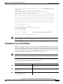
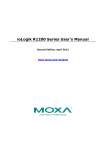
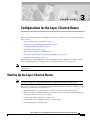
C H A P T E R
3
Configurations for the Layer 3 Switch Router
This chapter describes the initial configuration of the Layer 3 switch router and contains the following
major sections:
•
Starting Up the Layer 3 Switch Router, page 3-1
•
Using the Console and the Management Ports, page 3-2
•
Configuring the Management Port, page 3-3
•
Configuring the Hostname, page 3-5
•
Using the Bootflash Memory SIMM, page 3-5
•
Recovering a System Image Using Xmodem and Ymodem, page 3-10
•
Updating the System Image, page 3-13
This chapter takes you through Step 2 of the suggested process for configuring your Layer 3 switch
router (see the “Preparing to Configure the Layer 3 Switch Routers” section on page 2-1).
Note
You should have already set up the hardware before proceeding with the initial Layer 3 switch router
configuration.
Starting Up the Layer 3 Switch Router
Note
You must complete the tasks described here before configuring your Layer 3 switch router.
This section lists the tasks you should have completed during hardware installation, including starting
up the Layer 3 switch router. You should have:
•
Verified that the Layer 3 switch router is set for the correct AC (or DC) power voltages.
Refer to the Catalyst 2948G-L3 Hardware Installation Guide or the Catalyst 4908G-L3 Hardware
Installation Guide for correct power voltages.
•
Connected the cables to the Layer 3 switch router.
•
Connected the console terminal to the Layer 3 switch router.
•
Powered up the Layer 3 switch router.
Catalyst 2948G-L3 and Catalyst 4908G-L3 Switch Router Software Feature and Configuration Guide
78-10408-03
3-1
Chapter 3
Configurations for the Layer 3 Switch Router
Using the Console and the Management Ports
•
Entered the command line interface (CLI) configuration mode. You do this by answering no when
you are prompted to enter the initial dialog:
Would you like to enter the initial dialog? [yes]: no
You see the following user EXEC prompt:
Router>
Using the Console and the Management Ports
You can configure your Layer 3 switch router from a direct console connection to the console port or
remotely through its management port.
•
If you are using a direct console connection, configure your terminal emulation program for
9600 baud, 8 data bits, no parity, and 1 stop bit.
•
If you are configuring remotely through the management port, you must assign an IP address to any
Fast Ethernet or Gigabit Ethernet port on your Layer 3 switch router, which serves as a management
port.
For interface configuration instructions, see “Configuring the Management Port” section on page 3-3.
For further details on configuring ports and lines for management access, refer to the
Cisco IOS Configuration Fundamentals Configuration Guide.
Modem Support
Layer 3 switchYou can connect a modem to the console port or to the auxiliary port on the Layer 3 switch
router. The following settings on the modem are required:
•
Enable auto answer mode
•
Suppress result codes
You can configure your modem by setting the Dual In-line Package (DIP) switches on the modem or by
connecting the modem to terminal equipment. Refer to the user manual provided with your modem for
the correct configuration information.
Note
Because there are no hardware flow control signals available on the console port, the console port
terminal characteristics should match the modem settings.
For further details on configuring ports and modems for management access, see the Cisco IOS
Configuration Fundamentals Configuration Guide and Cisco IOS Dial Solutions Configuration Guide.
Modem Support for Recovering a System Image
The Catalyst 2948G-L3 and the Catalyst 4908G-L3 switch routers support Xmodem and Ymodem
protocols. If all of the system images in the bootflash memory are damaged or erased, you can copy an
image from a local or remote computer (such as a PC, UNIX workstation, or Macintosh computer) using
the Xmodem or Ymodem protocols. The Xmodem and Ymodem protocols support different speeds of
Catalyst 2948G-L3 and Catalyst 4908G-L3 Switch Router Software Feature and Configuration Guide
3-2
78-10408-03
Chapter 3
Configurations for the Layer 3 Switch Router
Configuring the Management Port
file transfer. The maximum file transfer speed supported is 57600 baud. This functionality primarily
serves as a disaster recovery technique in which you recover system images using Xmodem and
Ymodem commands on the ROM monitor from the console port on your Layer 3 switch router.
For more information on recovering a system image, see the “Recovering a System Image Using
Xmodem and Ymodem” section on page 3-10.
Passwords
There are two types of passwords that you can configure: an enable password and an enable secret
password. For maximum security, make the enable password different from the enable secret password.
•
Enable password—The enable password is a nonencrypted password. It can contain any number of
uppercase and lowercase alphanumeric characters. Give the enable password only to users permitted
to make configuration changes to the Layer 3 switch router.
•
Enable secret password—The enable secret password is a secure, encrypted password. By setting an
encrypted password, you can prevent unauthorized configuration changes. On systems running
Cisco IOS software, you enter the enable secret password before you can access global configuration
mode.You enter the enable secret password to access boot ROM software.
An enable secret password can contain from 1 to 25 uppercase and lowercase alphanumeric
characters. The first character cannot be a number. Spaces are valid password characters. Leading
spaces are ignored; trailing spaces are recognized.
You will configure passwords in the next section, “Configuring the Management Port.”
Configuring the Management Port
The management port on the Layer 3 switch router allows multiple simultaneous Telnet or SNMP
network management sessions. Since there is no separate management port on Layer 3 switch routers,
you can configure any Fast Ethernet or Gigabit Ethernet port as a management port.
You can remotely configure the Layer 3 switch router through the management port, but first you must
configure an IP address so that the Layer 3 switch router is reachable. You can manually configure the
management port interface from the CLI.
Note
Before you begin configuring the management port interface manually, get the Layer 3 switch router
IP address and IP subnet mask. Also make sure the console cable is connected to the console port.
You can configure the management port from an IP-connected network.
Catalyst 2948G-L3 and Catalyst 4908G-L3 Switch Router Software Feature and Configuration Guide
78-10408-03
3-3
Chapter 3
Configurations for the Layer 3 Switch Router
Configuring the Management Port
To configure Telnet for remote management access, perform the following procedure, beginning in user
EXEC mode:
Command
Purpose
Router> enable
Enter user EXEC (or enable) mode.
Router#
The # prompt indicates enable mode.
Router# configure terminal
Router(config)#
Enter global configuration mode. You can also
abbreviate the command to config terminal. The
Router(config)# prompt indicates that you are in global
configuration mode.
Step 3
Router(config)# enable
password password
Set the enable password. See the “Passwords” section on
page 3-3.
Step 4
Router(config)# enable secret password
Enter an enable secret password. A user must enter the
enable secret password to gain access to global
configuration mode.
Step 5
Router(config)# interface type number
Enter interface configuration mode on the Ethernet
interface.
Step 1
Step 2
Router(config-if)#
Step 6
Router(config-if)# ip address ip-address
subnetmask
Enter the IP address and IP subnet mask for the interface
specified in Step 5.
Step 7
Router(config-if)# no shutdown
Enable the interface.
Step 8
Router(config-if)# exit
Return to global configuration mode.
Router(config)#
Step 9
Router(config)# line vty line-number
Router(config-line)#
Enter line configuration mode for virtual terminal
connections. Commands entered in this mode control the
operation of Telnet sessions to the Layer 3 switch router.
Step 10
Router(config-line)# password password
Enter a password for Telnet sessions.
Step 11
Router(config-line)# end
Return to privileged EXEC mode.
Router#
Step 12
Router# copy running-config
startup-config
Note
Any Fast Ethernet interface 1–48 and any Gigabit Ethernet interface 49–50 on the
Catalyst 2948G-L3 switch router, or any Gigabit Ethernet interface 1–8 on the Catalyst 4908G-L3
switch router, can be configured as a management port.
Save your configuration changes to NVRAM.
Once you have completed configuring remote mangement on the management port, you can use Telnet
to remotely assign and verify configurations.
You can display the configuration file when you are in privileged EXEC (enable) mode.
•
To see the current operating configuration, enter the following command at the enable prompt:
Router# show running-config
Catalyst 2948G-L3 and Catalyst 4908G-L3 Switch Router Software Feature and Configuration Guide
3-4
78-10408-03
Chapter 3
Configurations for the Layer 3 Switch Router
Configuring the Hostname
•
To see the configuration in NVRAM, enter the following command:
Router# show startup-config
If you made changes to the configuration, but did not write the changes to NVRAM, the results of
show running-config will differ from the results of the show startup-config command.
Configuring the Hostname
In addition to the system passwords and enable password, your initial configuration should include the
hostname to make it easier to configure and troubleshoot the Layer 3 switch router. To configure the
hostname, perform the following task, beginning in enable mode:
Step 1
Command
Purpose
Router# configure terminal
Enter global configuration mode.
Router(config)#
Step 2
Router(config)# hostname name-string
Enter a system name. In this example, we set
the hostname to “Router.”
Step 3
Router(config)# end
Return to privileged EXEC mode.
Router#
Step 4
Router# copy running-config startup-config
Copy your configuration changes to NVRAM.
Using the Bootflash Memory SIMM
The Catalyst 2948G-L3 and Catalyst 4908G-L3 switch routers use the onboard bootflash memory as the
file storage system. The bootflash memory single inline memory module (SIMM) stores a copy of the
Layer 3 switch router’s software image. The following sections describe how to use the bootflash
memory SIMM to perform system administration:
•
Viewing the Contents of Bootflash Memory, page 3-5
•
Deleting Files from Bootflash Memory, page 3-6
•
Backing Up a System Image to a TFTP Server, page 3-6
•
Copying a System Image from a TFTP Server to a Bootflash Memory SIMM, page 3-7
•
Erasing Files from a Full Bootflash Memory SIMM, page 3-8
Viewing the Contents of Bootflash Memory
You can perform the following tasks to view the contents of the onboard bootflash memory SIMM:
•
To determine which file system device you are accessing, enter the print working directory (pwd)
command.
Router# pwd
bootflash:
Catalyst 2948G-L3 and Catalyst 4908G-L3 Switch Router Software Feature and Configuration Guide
78-10408-03
3-5
Chapter 3
Configurations for the Layer 3 Switch Router
Using the Bootflash Memory SIMM
To list the directory contents of any bootflash memory media, enter the dir [bootflash:] command.
•
Router# dir
Directory of bootflash:/
1
2
-rw-rw-
3153784
3153932
<no date>
<no date>
cat2948g-in-mz.old
cat2948g-in-mz
16777216 bytes total (7315372 bytes free)
Router#
Deleting Files from Bootflash Memory
When you delete a file from bootflash memory, the system marks the file as deleted. Deleted files cannot
be recovered. The bootflash memory is not released after the image file has been deleted; only the image
file is marked as deleted.
Caution
When deleting files from memory, be careful not to delete all the system images. You should always
retain one known good image as a backup image.
To delete a file, enter the delete command. The following example shows how to delete a specified image
file using the delete command:
Router# delete cat2948g-in-mz.old
Delete filename [cat2948g-in-mz.old]?
Delete bootflash:cat2948g-in-mz.old? [confirm]
Router# dir
Directory of bootflash:/
2
-rw-
3153932
<no date>
cat2948g-in-mz
16777216 bytes total (7315372 bytes free)
Backing Up a System Image to a TFTP Server
To create a backup copy of your system image, you can copy system images from bootflash memory to
a Trivial File Transfer Protocol (TFTP) server.
In some implementations of TFTP, you must create a dummy file on the TFTP server and give it read,
write, and execute permissions before copying the file over it. Refer to your TFTP documentation for
more information.
Tip
Before you copy software between the network server and bootflash memory in the Layer 3 switch
router, do the following:
– Make sure that you have access to the network server and that you know its IP address and name.
– Verify that the server has sufficient room to accommodate the Cisco IOS software image.
– Check the filename requirements and verify that there is enough file space on the network server.
Catalyst 2948G-L3 and Catalyst 4908G-L3 Switch Router Software Feature and Configuration Guide
3-6
78-10408-03
Chapter 3
Configurations for the Layer 3 Switch Router
Using the Bootflash Memory SIMM
To create a backup of the system software on a TFTP server, perform the following task, beginning in
privileged EXEC mode:
Step 1
Command
Purpose
Router# dir bootflash:
Display the contents of bootflash memory,
including the names of the images that
currently reside there.
Note the name of the image file you want to
copy.
Step 2
Router# copy bootflash: tftp:
Copy a file from bootflash memory to a TFTP
server. Be sure to include a colon at the end of
the tftp keyword, as shown in this example.
The following example demonstrates how to copy a specified system image file from the bootflash
memory to the default TFTP server:
Router# copy bootflash: tftp:
Source filename []? cat2948g-in-mz.120-7.W5.14.46
Address or name of remote host []? 171.10.0.111
Destination filename [cat2948g-in-mz.120-7.W5.14.46]? yes
!!.!.!!!!!!!!!.!!!!!!!!!.!.!!!!!!!!!.!.!!.!.!!!!!!!!!.!.!.!!!!!!!!!.!!!!!!!!!.!!
!!!!!!!!.!.!!!!!!!!!.!!!!!!!!!!.!!!!!!!!!.!!!!!!!!!.!!!!!!!!!.!.!.!!!!!!!!!.!!.!
!!!!!!!!.!.!.!.!!!!!!!!!.!.!!.!.!!!!!!!!!.!!!!!!!!!.!.!!!!!!!!!!.!!!!!!!!!.!.!.!
!!!!!!!!.!!!!!!!!!.!!!!!!!!!.!!.!.!!!!!!!!!.!!.!.!.!!!!!!!!!!.!!!!!!!!!.!.!!.!!!
!!!!!!.!.!.!.!.!!!!!!!!!.!!.!.!.!!!!!!!!!.!!!!!!!!!!.!!!!!!!!!.!.!!.!!!!!!!!!.!!
!!!!!!!!.!.!.!.!!!!!!!!!.!!!!!!!!!.!.!!.!.!!!!!!!!!.!!.!.!.!.!!!!!!!!!!.!!!!!!!!
!.!.!!.!!!!!!!!!.!.!!!!!!!!!!.!!!!!!!!!.!!.!!!!!!!!!.!.!.!!!!!!!!!.!.!.!!!!!!!!!
!!!!!!!!.!!!!!!!!!.!.!.!!!!!!!!!.!!.!.!!!!!!!!!.!!.!.!.!!!!!!!!!.!!.!.!.!.!.!!!!
!!!
3173364 bytes copied in 743.840 secs (4271 bytes/sec)
Copying a System Image from a TFTP Server to a Bootflash Memory SIMM
You can copy system image files from a TFTP server to the bootflash memory SIMM for use in booting
the Layer 3 switch router.
It is a good idea to have a copy of the current system image on the bootflash memory SIMM in case the
new image file that you copy from the TFTP server is corrupted.
Note
You can also create a backup copy of your system image by copying the system image from bootflash
memory to a TFTP server. You can maintain a known good image as a backup image on the TFTP
server. If the new image file you copy from the TFTP server is corrupted, you can retrieve the known
good backup copy of the system image file from the TFTP server.
Catalyst 2948G-L3 and Catalyst 4908G-L3 Switch Router Software Feature and Configuration Guide
78-10408-03
3-7
Chapter 3
Configurations for the Layer 3 Switch Router
Using the Bootflash Memory SIMM
To copy the system image from the TFTP server to a bootflash memory SIMM, perform the following
procedure, beginning in privileged EXEC mode:
Command
Purpose
Step 1
Router# dir bootflash:
Display the contents of bootflash memory,
including the names of the images that
currently reside there.
Step 2
Router# copy tftp: bootflash:
Copy a file from a TFTP server to bootflash
memory.
The following example demonstrates how to copy a system image from the TFTP server to the bootflash
memory SIMM without erasing the previous image file.
Note
To retain existing images on the bootflash memory, enter no when you are prompted to confirm
erasing bootflash memory.
Router# copy tftp: bootflash:
Address or name of remote host [172.10.00.00]?
Source filename [domino/cat2948g-in-mz.120-7.W5.14.45]? domino/cat2948g-in-mz.12
0-7.W5.14.46
Destination filename [cat2948g-in-mz.120-7.W5.14.46]?
Accessing tftp://172.10.00.00/domino/cat2948g-in-mz.120-7.W5.14.46...
Erase bootflash: before copying? [confirm] no
Loading domino/cat2948g-in-mz.120-7.W5.14.46 from 172.10.00.00 (via FastEthernet
1): !!!!!!!!!!!!!!!!!!!!!!!!!!!!!!!!!!!!.!!!!!!!!!!!!!!!!!!!!!!!!!!!!!!!!!!!!!!!
!!!!!!!!!!.!!!!!!!!!!!!!!!!!!!!!!!!!!!!!!!!!!!!!!!!!!!!!!!!!!!!!!!.!!!!!!!!!!!!!
!!!!!!!!!!!!!!!!!!!!!!!!!!!!!!!!!!!!!!!!.!!!!!!!!!!!!!!!!!!!!!!!!!!!!!!!!!!!!!!!
!!!!!!!!!!!.!!!!!!!!!!!!!!!!!!!!!!!!!!!!!!!!!!!!!!!!!!!!!!!!!!!!.!!!!!!!!!!!!!!!
!!!!!!!!!!!!!!!!!!!!!!!!!!!!!!!!!!!!.!!!!!!!!!!!!!!!!!!!!!!!!!!!!!!!!!!!!!!!!!!!
!!!!!!!!.!!!!!!!!!!!!!!!!!!!!!!!!!!!!!!!!!!!!!!!!!!!!!!!!!!!!!.!!!!!!!!!!!!!!!!!
!!!!!!!!!!!!!!!!!!!!!!!!!!!!!!!!!!!!.!!!!!!!!!!!!!!!!!!!!!!!!!!!!!!!!!!!!!!!!!!!
!!!!!!!!!!!!.!!!!!!!!!!!!!!!!!!!!!!!!!!!!!!!!!!!!!!!!!!!!!!!!!!.!!!!!!!!!!!!!!!!
!
[OK - 3173364/6345728 bytes]
Verifying checksum... OK (0x755F)
3173364 bytes copied in 210.364 secs (15111 bytes/sec)
Router# dir bootflash:
Directory of bootflash:/
1
2
-rw-rw-
3173128
3173364
<no date>
<no date>
cat2948g-in-mz.120-7.W5.14.45
cat2948g-in-mz.120-7.W5.14.46
16777216 bytes total (10430596 bytes free)
Erasing Files from a Full Bootflash Memory SIMM
If the bootflash memory becomes full, you must erase all the files in the bootflash memory file system
before copying a new image file from the TFTP server.
Catalyst 2948G-L3 and Catalyst 4908G-L3 Switch Router Software Feature and Configuration Guide
3-8
78-10408-03
Chapter 3
Configurations for the Layer 3 Switch Router
Using the Bootflash Memory SIMM
Note
When bootflash memory is full, it is important to make a copy of a known good image file, and then
copy a new system image file. If the new image file you copy from the TFTP server becomes
corrupted, you can revert to the copy of the known good system image file. For detailed information
on how to make a copy of a known good image file, and then copy a new system image file, see the
“Copying the System Image to the Layer 3 Switch Router” section on page 3-13.
To erase and clean bootflash memory and then copy the new system image from the TFTP server to
bootflash memory, perform the following procedure, beginning in privileged EXEC mode:
Command
Purpose
Step 1
Router# dir bootflash:
Display the contents of bootflash memory,
including the names of the images that
currently reside there.
Step 2
Router# copy tftp: bootflash:
Erase bootflash memory and copy a file from
a TFTP server to bootflash memory.
The following example demonstrates how to erase and clean bootflash memory and then copy the new
system image from the TFTP server to the bootflash memory SIMM.
Note
To erase a full bootflash memory, enter yes when you are prompted to confirm erasing bootflash
memory.
Router# copy tftp bootflash:
Address or name of remote host []? 172.10.00.00
Source filename []? domino/cat2948g-in-mz.120-7.W5.14.46
Destination filename [cat2948g-in-mz.120-7.W5.14.46]?
Accessing tftp://172.10.00.00/domino/cat2948g-in-mz.120-7.W5.14.46...
Erase bootflash: before copying? [confirm] yes
Erasing the bootflash filesystem will remove all files! Continue? [confirm] yes
Erasing device... eeeeeeeeeeeeeeeeeeeeeeeeeeeeeeeeeeeeeeeeeeeeeeeeeeeeeeeeeeeeee
ee ...erased
Erase of bootflash: complete
Loading domino/cat2948g-in-mz.120-7.W5.14.46 from 172.10.00.00 (via FastEthernet1):
!!.!!!!.!!!!!!!!!!!!!!!!!!!!!!!!!!!!!!!!!!!!!!!!!!!!!!.!!!!!!!!!!!!!!!!!!!!!!!!!!
!!!!!.!!!!!!!!!!!!!!!!!!!!!!!!!!!!!!!!!!!!!!!!!!!!!!!!!!!.!!!!!!!!!!!!!!!!!!!!!!
!!!!!!!!!!!!!!!!!!!!!!!.!!!!!!!!!!!!!!!!!!!!!!!!!!!!!!!!!!!!!!!!!!!!!!!!!!!!!!.!
!!!!!!!!!!!!!!!!!!!!!!!!!!!!!!!!!!!!!!!!!!!!!!!!!!!!.!!!!!!!!!!!!!!!!!!!!!!!!!!!
!!!!!!!!!!!!!!!!!!!!!!!!!!.!!!!!!!!!!!!!!!!!!!!!!!!!!!!!!!!!!!!!!!!!!!!!!!!!!!!!
.!!!!!!!!!!!!!!!!!!!!!!!!!!!!!!!!!!!!!!!!!!!!!!!!!!!!!!!.!!!!!!!!!!!!!!!!!!!!!!!
!!!!!!!!!!!!!!!!!!!!!!!!!!!!!!!!.!!!!!!!!!!!!!!!!!!!!!!!!!!!!!!!!!!!!!!!!!!!!!!!
!!!!!!!!.!!!!!!!!!!!!!!!!!!!!!!!!!!!!!!!!!!!!!!!!!!!!!!!!!!!!!!.!!!!!!!!!!!!!!!!
!!!!!
[OK - 3173128/6345728 bytes]
Verifying checksum... OK (0x799F)
3173128 bytes copied in 177.668 secs (17927 bytes/sec)
Router# dir bootflash:
Directory of bootflash:/
1
-rw-
3173128
<no date>
cat2948g-in-mz.120-7.W5.14.46
16777216 bytes total (13604024 bytes free)
Catalyst 2948G-L3 and Catalyst 4908G-L3 Switch Router Software Feature and Configuration Guide
78-10408-03
3-9
Chapter 3
Configurations for the Layer 3 Switch Router
Recovering a System Image Using Xmodem and Ymodem
Recovering a System Image Using Xmodem and Ymodem
If you do not have access to a network server and need to download a system image, you can copy an
image from a local or remote computer (such as a PC, UNIX workstation, or Macintosh computer) using
the Xmodem or Ymodem protocols.
Xmodem and Ymodem are common protocols used for transferring files and are included in applications
such as Windows 3.1 (TERMINAL.EXE), Windows 95 (HyperTerminal), Windows NT 3.5x
(TERMINAL.EXE), Windows NT 4.0 (HyperTerminal), and Linux UNIX freeware (minicom).
Xmodem and Ymodem downloads are slow, so you should use them only when you do not have access
to a network server. You can speed up the transfer by setting the transfer port speed to 57600 bps.
If all local system images are damaged or erased on your Layer 3 switch router, you can perform the file
transfer by using the ROM monitor. On the Catalyst 2948G-L3 and the Catalyst 4908G-L3 switch
routers, you can perform the file transfer from the ROM monitor over the console port.
Note
Perform file transfer from the ROM monitor with either Cisco IOS Release 12.0(7)W5(15a) or later.
To verify the ROM monitor version, enter either the Cisco IOS show version command or enter the
reset command from ROMMON mode.
Figure 3-1 shows a file transfer using the Xmodem or Ymodem protocols. The connection is from either
a local or a remote computer to your Layer 3 switch router. You can make the connection using either
the COM port on the local computer or using a modem with the remote computer.
Figure 3-1
Transferring a System Image to a Layer 3 Switch Router Using Xmodem and Ymodem
Protocols
Catalyst 2948G-L3 or
Catalyst 4908G-L3 switch
router downloading a
Cisco IOS software image
from a local or remote PC
Local PC running
terminal emulation
software and Xmodem
and Ymodem protocols
Modem
Remote PC
running terminal
emulation software
and Xmodem and
Ymodem protocols
38417
Modem
Console
port
Telephone
network
Catalyst 2948G-L3 and Catalyst 4908G-L3 Switch Router Software Feature and Configuration Guide
3-10
78-10408-03
Chapter 3
Configurations for the Layer 3 Switch Router
Recovering a System Image Using Xmodem and Ymodem
To copy a Cisco IOS image from a computer or workstation to a router using the Xmodem or Ymodem
protocol, perform the following procedure:
Task
Command
Copy a system image from a computer to DRAM xmodem [-c | -y | -s ]
using the ROM monitor.
The -c option provides cyclic redundancy check
(CRC)-16 checksumming; -y uses the Ymodem
protocol; and -s sets the console port data rate or
speed. Speeds range from 1200 bps to 57600 bps.
The computer from which you transfer the Cisco IOS image must be running terminal emulation
software and the Xmodem or Ymodem protocol.
Example of Xmodem Transfer Using the ROM Monitor Mode
This section explains how to transfer a Cisco IOS image file using the ROM monitor mode and the
Xmodem protocol. You can download an image from Cisco.com.
The Catalyst 2949G-L3 and the Catalyst 4908G-L3 switch routers must have enough DRAM to hold the
IOS image file being transferred. The transferred IOS image runs only in DRAM and cannot be stored
in bootflash memory. After your Layer 3 switch router boots up with the transferred image, you can copy
a good IOS image from a TFTP server onto the bootflash file system.
Caution
Having a modem connection from the telephone network to your console port introduces security
issues that you should consider before enabling the connection. For example, remote users can dial
in to your modem and access the Layer 3 switch router’s configuration settings.
To download an IOS image from the ROM monitor mode (using the Xmodem and Ymodem protocols),
perform the following steps:
Step 1
Place the Cisco IOS software image on the remote computer’s hard drive.
Step 2
Transfer the image from either a remote or a local computer.
•
To transfer the image from a remote computer:
– Connect a modem to the console port of your Layer 3 switch router and to the standard
telephone network. The modem and console port must communicate at the same speed, which
can be from 1200 to 57600 bps, depending on the speed supported by your modem.
Note
We recommend that you use the maximum speed of 57600 bps.The size of an IOS image is
approximately 3 MB and takes about 10 minutes to transfer at 57600 bps.
– Enter the confreg ROM monitor command to configure the console port transmission speed for
the Layer 3 switch router. You can also set the transmission speed with the -s option.
– Connect a modem to the remote computer and to the telephone network. The remote computer
dials through the telephone network and connects to the Layer 3 switch router.
Catalyst 2948G-L3 and Catalyst 4908G-L3 Switch Router Software Feature and Configuration Guide
78-10408-03
3-11
Chapter 3
Configurations for the Layer 3 Switch Router
Recovering a System Image Using Xmodem and Ymodem
If you are transferring from a local computer, you may need to configure the terminal
emulation program to ignore Ready to Send/data terminal ready (RTS/DTR) signals.
Note
•
To transfer the image from a local computer:
– Connect the Layer 3 switch router’s console port to a COM port (serial port) on the computer,
using a null-modem cable. The console port speed configured on the router must match the
transfer speed configured on the local computer.
You see a ROM monitor prompt in the terminal emulation window:
rommon >
Step 3
Enter the xmodem ROM monitor command.
The image is downloaded to DRAM and normally executes on completion of the file transfer. The -c
option specifies CRC-16 checksum, which is more thorough than a standard checksum, if supported by
your computer.
The following example shows how to use the xmodem command to transfer an IOS image in ROM
monitor:
rommon
Do not
Invoke
Do you
> xmodem -y -s57600
start sending the image yet...
this application for disaster recovery.
wish to continue? y/n [n]: yes
Note, if the console port is attached to a modem, both the
console port and the modem must be operating at the same baud
rate. Use console speed 57600 bps for download [confirm]
Download will be performed at 57600. Make sure your terminal
emulator is set to this speed before sending file.
Ready to receive file ...
Step 4
Start an Xmodem send operation.
Xmodem send operations are initiated from the terminal emulation software on the local or remote
computer that is sending the system image to the Layer 3 switch router. Refer to your emulation software
application’s manual for instructions on how to execute an Xmodem file transfer.
Note
Step 5
The remote connection terminates when you reset the speed on the terminal emulator.
Reset the speed on the terminal emulator back to 9600 bps after you complete the transfer of the IOS
image into DRAM.
You see the following output upon completion of the IOS image transfer:
Returning console speed to 9600.
Please reset your terminal emulator to this speed...
and hit 'y' to continue
Step 6
Disconnect the modem from the console port and reconnect the terminal line. Enter yes to continue. Your
Layer 3 switch router automatically reboots with the IOS image.
Step 7
Download an image from Cisco.com onto the bootflash file system after your Layer 3 switch router
reboots.
Catalyst 2948G-L3 and Catalyst 4908G-L3 Switch Router Software Feature and Configuration Guide
3-12
78-10408-03
Chapter 3
Configurations for the Layer 3 Switch Router
Updating the System Image
Updating the System Image
This section provides brief instructions for updating the system image on your Layer 3 switch router.
This procedure assumes that you are manually booting the Layer 3 switch router from a system image
on the bootflash memory SIMM. You can also configure the Layer 3 switch router to boot automatically
from a system image specified in the BOOT environment variable. For additional information on booting
options and maintaining system images, refer to the Cisco IOS Configuration Fundamentals
Configuration Guide.
To update the system software, do the following:
Step 1
Download the system image from Cisco.com.
Step 2
Copy the system image to the Layer 3 switch router.
Step 3
Reload the Layer 3 switch router with the new image.
Downloading System Images from Cisco.com
Cisco IOS system images, along with other software, are available from the Software Center on
Cisco.com at http://www.Cisco.com. You can download system images from Cisco.com using your
browser’s FTP capability, using conventional FTP, or using Cisco.com’s asynchronous dial-up interface.
For instructions on accessing and downloading software from Cisco.com, refer to the Software
Downloading from Cisco.com via World Wide Web publication at the Software Center on Cisco.com.
Copying the System Image to the Layer 3 Switch Router
You can copy the system image to the Layer 3 switch router using TFTP, FTP, or rcp. If the system you
used to download the image from Cisco.com does not function as a TFTP, FTP, or rcp server, you must
first copy the file to an intermediate server that provides those services to your Layer 3 switch router.
Note
Before copying the system image from the server to the Layer 3 switch router, check the size of the
file to make sure you will have enough room for your Layer 3 switch router’s bootflash memory.
If the bootflash memory is full, you must erase all the files in the bootflash memory file system before
copying a new image file from the TFTP server. In addition, before you copy a new image from the TFTP
server, you must first download a copy of your known good image. If the new image file you copy from
the TFTP server is corrupted, you can revert to the known good image.
Catalyst 2948G-L3 and Catalyst 4908G-L3 Switch Router Software Feature and Configuration Guide
78-10408-03
3-13
Chapter 3
Configurations for the Layer 3 Switch Router
Updating the System Image
To copy both the known good system image and the new system image from a TFTP server to the file
system on your Layer 3 switch router, initiate a Telnet session or console connection to the Layer 3
switch router, perform the following task in privileged EXEC mode:
Command
Purpose
Step 1
Router# dir bootflash:
Display the contents and available space in bootflash memory. If
there is not enough free space to copy the new system image, do
Steps 2 through 5. If there is enough space, proceed to Step 4.
Step 2
Router# copy tftp: bootflash:
Erase bootflash memory and copy a file from a TFTP server to
bootflash memory. Make sure you copy the known good system
image file.
Step 3
Router# dir bootflash:
Display the contents of bootflash memory. This step confirms that
space was available in bootflash memory and the known good
image file was copied as expected. You can then proceed to
download the latest image.
Step 4
Router# copy tftp: bootflash:
Initiate a TFTP session to copy the new system image from the
TFTP server.
Step 5
Router# dir bootflash:
Display the contents of bootflash memory again, to confirm that
the latest image file was copied as expected.
The following example shows how to erase a full bootflash memory file system, copy a known good
image, and copy the latest image using TFTP:
Router# copy tftp bootflash:
Address or name of remote host []? 172.10.00.00
Source filename []? domino/cat2948g-in-mz.120-7.W5.14.45
Destination filename [cat2948g-in-mz.120-7.W5.14.45]?
%Warning:There is a file already existing with this name
Do you want to over write? [confirm] yes
Accessing tftp://172.10.00.00/domino/cat2948g-in-mz.120-7.W5.14.45...
Erase bootflash: before copying? [confirm] yes
Erasing the bootflash filesystem will remove all files! Continue? [confirm] yes
Erasing device... eeeeeeeeeeeeeeeeeeeeeeeeeeeeeeeeeeeeeeeeeeeeeeeeeeeeeeeeeeeeee
ee ...erased
Erase of bootflash: complete
Loading domino/cat2948g-in-mz.120-7.W5.14.45 from 172.10.00.00 (via FastEthernet 1):
!!!!!!.!!!!!!!!!!!!!!!!!!!!!!!!!!!!!!!!!!!!!!!!!!!!!!.!!!!!!!!!!!!!!!!!!!!!!!!!!
!!!!!.!!!!!!!!!!!!!!!!!!!!!!!!!!!!!!!!!!!!!!!!!!!!!!!!!!!.!!!!!!!!!!!!!!!!!!!!!!
!!!!!!!!!!!!!!!!!!!!!!!.!!!!!!!!!!!!!!!!!!!!!!!!!!!!!!!!!!!!!!!!!!!!!!!!!!!!!!.!
!!!!!!!!!!!!!!!!!!!!!!!!!!!!!!!!!!!!!!!!!!!!!!!!!!!!.!!!!!!!!!!!!!!!!!!!!!!!!!!!
!!!!!!!!!!!!!!!!!!!!!!!!!!.!!!!!!!!!!!!!!!!!!!!!!!!!!!!!!!!!!!!!!!!!!!!!!!!!!!!!
.!!!!!!!!!!!!!!!!!!!!!!!!!!!!!!!!!!!!!!!!!!!!!!!!!!!!!!!.!!!!!!!!!!!!!!!!!!!!!!!
!!!!!!!!!!!!!!!!!!!!!!!!!!!!!!!!.!!!!!!!!!!!!!!!!!!!!!!!!!!!!!!!!!!!!!!!!!!!!!!!
!!!!!!!!.!!!!!!!!!!!!!!!!!!!!!!!!!!!!!!!!!!!!!!!!!!!!!!!!!!!!!!.!!!!!!!!!!!!!!!!
!!!!!
[OK - 3173128/6345728 bytes]
Verifying checksum... OK (0x799F)
3173128 bytes copied in 177.668 secs (17927 bytes/sec)
Router# dir bootflash:
Directory of bootflash:/
1
-rw-
3173128
<no date>
cat2948g-in-mz.120-7.W5.14.45
16777216 bytes total (13604024 bytes free)
Router# copy tftp: bootflash:
Address or name of remote host [172.10.00.00]?
Catalyst 2948G-L3 and Catalyst 4908G-L3 Switch Router Software Feature and Configuration Guide
3-14
78-10408-03
Chapter 3
Configurations for the Layer 3 Switch Router
Updating the System Image
Source filename [domino/cat2948g-in-mz.120-7.W5.14.45]? domino/cat2948g-in-mz.12
0-7.W5.14.46
Destination filename [cat2948g-in-mz.120-7.W5.14.46]?
Accessing tftp://172.10.00.00/domino/cat2948g-in-mz.120-7.W5.14.46...
Erase bootflash: before copying? [confirm] no
Loading domino/cat2948g-in-mz.120-7.W5.14.46 from 172.10.00.00 (via FastEthernet1):
!!!!!!!!!!!!!!!!!!!!!!!!!!!!!!!!!!!!!!!!.!!!!!!!!!!!!!!!!!!!!!!!!!!!!!!!!!!!!!!!
!!!!!!!!!!.!!!!!!!!!!!!!!!!!!!!!!!!!!!!!!!!!!!!!!!!!!!!!!!!!!!!!!!.!!!!!!!!!!!!!
!!!!!!!!!!!!!!!!!!!!!!!!!!!!!!!!!!!!!!!!.!!!!!!!!!!!!!!!!!!!!!!!!!!!!!!!!!!!!!!!
!!!!!!!!!!!.!!!!!!!!!!!!!!!!!!!!!!!!!!!!!!!!!!!!!!!!!!!!!!!!!!!!.!!!!!!!!!!!!!!!
!!!!!!!!!!!!!!!!!!!!!!!!!!!!!!!!!!!!.!!!!!!!!!!!!!!!!!!!!!!!!!!!!!!!!!!!!!!!!!!!
!!!!!!!!.!!!!!!!!!!!!!!!!!!!!!!!!!!!!!!!!!!!!!!!!!!!!!!!!!!!!!.!!!!!!!!!!!!!!!!!
!!!!!!!!!!!!!!!!!!!!!!!!!!!!!!!!!!!!.!!!!!!!!!!!!!!!!!!!!!!!!!!!!!!!!!!!!!!!!!!!
!!!!!!!!!!!!.!!!!!!!!!!!!!!!!!!!!!!!!!!!!!!!!!!!!!!!!!!!!!!!!!!.!!!!!!!!!!!!!!!!
!
[OK - 3173364/6345728 bytes]
Verifying checksum... OK (0x755F)
3173364 bytes copied in 210.364 secs (15111 bytes/sec)
Router# dir bootflash:
Directory of bootflash:/
1
2
-rw-rw-
3173128
3173364
<no date>
<no date>
cat2948g-in-mz.120-7.W5.14.45
cat2948g-in-mz.120-7.W5.14.46
16777216 bytes total (10430596 bytes free)
Note
Make sure that the file size of the image file you copied to bootflash memory matches the image file
size on the server.
Reloading the Layer 3 Switch Router
When the configuration register is set for manual booting, entering the reload command causes the
system to enter ROM monitor mode, where you enter the boot command and the name of the system
image to use. To perform this procedure, you must be connected to the console port, which provides
access to the Layer 3 switch router when in ROM monitor mode. For automatic booting, you can enter
the reload command from an Ethernet connection to the route processor.
Note
This procedure assumes that you need to change the boot field in the configuration register from its
default value so that the system reverts to ROM monitor mode when you enter the reload command.
To reload the Layer 3 switch router with the new system image in bootflash memory, perform the
following procedure, beginning in global configuration mode:
Command
Purpose
Step 1
Router(config)# config-register 0x0
Set the configuration register for manual booting from ROM
monitor mode. 1
Step 2
Router(config)# end
Return to privileged EXEC mode.
Router#
Step 3
Router# copy system:running-config Save your configuration changes to NVRAM.
nvram:startup-config
Catalyst 2948G-L3 and Catalyst 4908G-L3 Switch Router Software Feature and Configuration Guide
78-10408-03
3-15
Chapter 3
Configurations for the Layer 3 Switch Router
Updating the System Image
Step 4
Command
Purpose
Router# reload
Initiate a reload of the system software. You automatically
enter ROM monitor mode.
rommon 1>
Step 5
rommon 1> dir bootflash:
Display the contents of the file system. Perform this optional
step to display and copy the name of the system image to the
clipboard for use in Step 6.
Step 6
rommon 2> boot bootflash:filename
Reboot the Layer 3 switch router with the new system image.
You can paste the filename from the clipboard if you copied
it in Step 5.
Step 7
Router> show version
Display the system software version information. Use this
step to confirm that the system is loaded with the expected
software version.
1.
For details on using the configuration register to set boot parameters, refer to the Cisco IOS Configuration Fundamentals
Configuration Guide.
The following example shows how to enter terminal configuration mode, set the configuration register,
save the configuration, and reload the Layer 3 switch router with the new image on the bootflash memory
SIMM:
Router# configure terminal
Router(config)# config-register 0x0
Router(config)# end
Router#
4d00h: %SYS-5-CONFIG_I: Configured from console by console
Router#copy system:running-config nvram:startup-config
Destination filename [startup-config]?
Building configuration...
[OK]
Router# reload
Proceed with reload? [confirm]
rommon 1 > dir bootflash:
File size
Checksum
File name
3173128 bytes (0x306b08)
0x799f
cat2948g-in-mz.120-7.W5.14.45
3173364 bytes (0x306bf4)
0x755f
cat2948g-in-mz.120-7.W5.14.46
rommon 2 > boot bootflash:cat2948g-in-mz.120-7.W5.14.46
Self decompressing the image : #################################################
################################################################################
################################################################################
################################################################## [OK]
<The system boots>
Router> show version
Cisco Internetwork Operating System Software
IOS (tm) L3 Switch/Router Software (CAT2948G-IN-M), Version 12.0(7)W5(14.46)
TERIM TEST SOFTWARE
Copyright (c) 1986-2001 by cisco Systems, Inc.
Compiled Tue 22-Feb-00 04:31 by
Image text-base: 0x60010928, data-base: 0x605B2000
IN
Now that you have completed the initial configurations on your Layer 3 switch router, you can begin
configuring the interfaces. For more information on reloading a Layer 3 switch router see Chapter 4,
“Configuring Interfaces.”
Catalyst 2948G-L3 and Catalyst 4908G-L3 Switch Router Software Feature and Configuration Guide
3-16
78-10408-03