1
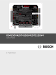
1 | Overview
2.1 | Set the B450 address
The B450 Bus Communicator Interface Module (wired to a
compatible control panel) is a four-wire powered SDI2, SDI, or
Option bus device that provides two-way communication over
commercial cellular networks using a plug-in communicator.
The B450 address switch determines the bus address of
the device. Set the address switch per the control panel
configuration. If multiple B450 devices reside on the same
system, each B450 module must have a unique system address,
and cannot share the same address value. Figure 2.1 shows the
address switch settings for address 01. Refer to Table 2.1 for
panel-specific settings.
The B450 on-board rotary switch determines the bus address of
the device. Configuration of the B450 is performed via USB or
SMS. On SDI2 control panels configuration can also be done on
the keypad or through Remote Programming Software (RPS).
Callout ― Description
1 ― Tamper switch connector
2 ― Address switch
3 ― MODE 2-pin connector (for future use)
4 ― Bus address label
5 ― USB connector
6 ― Heartbeat LED
7 ― RX LED (indicates packets received from the wireless network)
8 ― TX LED (indicates packets transmitted over the wireless network)
Control Panels
Switch
Position
Control
Panel
Address
Bus
Type
Function
USB or SMS
configuration setting
0
n/a
Any
Change
Configuration
B5512/B4512/B3512/
D9412GV4/D7412GV4/
D7212GV4/
Solution 2000/3000
1
1
SDI2
Automation, RPS,
or Reporting
D9412GV4/D7412GV4/
D7212GV4
Solution 2000/3000
2
2
SDI2
Automation, RPS,
or Reporting
D9412GV4/D7412GV4/
D7212GV4/D9412GV3/
D7412GV3/D7212GV3
D9412GV2/D7412GV2/
D7212GV2 v7.06+
4
88
SDI1
RPS or Reporting
D9412GV4/D7412GV4/
D7212GV4
D9412GV3/D7412GV3/
D7212GV3
5
92
SDI
AMAX 2000/2100/3000/
4000
CMS 6/8/40
Easy Series v3+
6
134
Option
RPS or Reporting
FPD-7024 v1.03+
9
250
Option
RPS or Reporting
Figure 3.3: Using SDI2 terminal strip or SDI2 interconnect cable
3 ― B450
wiring (B5512 control panel shown).
3.2 | Install the module
Mount the B450 into the enclosure’s 3-hole mounting pattern
using the supplied mounting screws, and secure the antenna
onto the enclosure. Mount the B450 into the interior side of
the enclosure. Refer to Figure 3.2.
Callout ― Description
1 ― Control panel (B5512 shown)
2 ― B450 module
3 ― Terminal wiring strip
4 ― Interconnect wiring (P/N: F01U079745) (included)
You can configure the B450 using one of the methods described
in this section for your control panel type.
RPS or Reporting
For D9412GV4/D7412GV4/D7212GV4 configurations, SDI2 bus connection
is the recommended configuration option, but SDI bus configuration is also
supported.
4.1 | Plug and play configuration
When installing under the following conditions, the B450 needs
no further configuration to communicate:
–– AES Encryption is not required.
–– Low signal delay can be no more than 200 sec.
1
Perform the following steps to install the B450.
NOTICE!
The module reads the address switch setting only
during power up. If you change the switch after
you apply power to the module, you must cycle the
power to the module in order for the new setting to
be enabled.
2 ― B44x cellular communication module (available separately)
4 | Configuration
1
10 ― Interconnect wiring connectors (to control panel bus or other
The address switch determines the bus address for the
B450 module. The control panel requires the address for
communications. Use a slotted screwdriver to set the address
switch.
Callout ― Description
1 ― SIM card
3 | Installation
2 | SDI2 address settings
2
Figure 3.1.2: Inserting the communication module
9 ― Terminal strip (to control panel bus)
compatible modules)
2
3
1
Figure 2.1: Address switch set to address 1
Figure 1.1: Board overview
3
NOTICE!
Remove power to the control panel prior to wiring
a B450 module to the control panel using either the
terminal strip wiring or interconnect cable to wire to
the control panel. Do not use both.
3.1 | Insert the module into the B450
Insert the communication module into the slot of the B450,
depending on your communication module (one with a SIM
card, or one without). Refer to Figure 3.1.2.
Figure 3.3: Installing the module
Callout ― Description
1 ― B450
2 ― Enclosure
3 ― Mounting screws (3)
4 ― B44x plug-in cellular communicator antenna (routed through
any knock-out)
5 ― B44x plug-in cellular communicator antenna cable (connected
to the communication module)
3.3 | Wire to the control panel
When wiring a B450 to a control panel, you can use either the
module’s terminal strip labeled with PWR, A, B, and COM or
the module’s interconnect wiring connectors (wire included).
Interconnect wiring parallels the PWR, A, B, and COM terminals
on the terminal strip. Figure 1.1 indicates the location of both
the terminal strip and the interconnect connect connectors on
the module.
NOTICE!
UL requires that for security installations, the B450
module be installed in a UL Listed enclosure with a
tamper.
4.2 | Configuring with SDI2 control panels
An SDI2-compatible control panel automatically configures a
connected module.
1. Power off the compatible control panel.
2. Set the address switch to the correct address for the control
panel (SDI2 control panels use address 1 or 2).
3. Connect the module to the control panel bus and apply
power.
4. Program the control panel communication settings using
RPS or the keypad.
4.3 | Configuring with SMS
The B450 supports configuration by SMS. You can send SMS via
mobile phone to the B450. For more information, refer to the
B450 Installation and Operation Guide.
NOTICE!
Power up the B450 with the address switch set
to the desired bus. When ready to program using
SMS, turn the switch to position 0. When done
programming, turn the switch back. Failure to return
the address switch to the previous setting will result
in a troubled condition.
4.4 | Configuring with USB
Flash pattern
Function
The B450 supports configuration by USB. Before you can access
the USB interface, you must install the RBUS1CP.inf file on the
target PC or laptop. The RBUS1CP.inf file is available on the
supplied CD-ROM.
RX (Receive) Flashing
Occurs when the module
receives a message from
over-the-air.
NOTICE!
Power up the B450 with the address switch set
to the desired bus. When ready to program using
USB, turn the switch to position 0. When done
programming, turn the switch back. Failure to return
the address switch to the previous setting will result
in a trouble condition.
4.4.1 | Install a communication program
To use USB connection from a computer to the B450 to
configure the B450, you must use a terminal emulator software
program such as Tera Term, located on the included B450 CDROM.
4.4.2 | Connect via USB cable
Insert one end of the USB cable into the PC or laptop, and insert
the other end into the B450 USB port.
NOTICE!
USB connection via the USB cable is only used for
temporary configuration programming.
4.4.3 | Log into USB interface
Log into the USB interface and make your selections. For more
information, refer to the B450 Installation and Operation Guide.
5 | LED descriptions
TX (Transmit) Flashing
Table 5.2: RX/TX LEDs Description
6 | Show the firmware version
To review the firmware version using an LED flash pattern,
tamper the B450.
Refer to Section 5 for flash patterns.
To tamper the B450, do one of the following:
–– If the optional tamper switch is installed:
With the enclosure door open, close the tamper
switch.
–– If the optional tamper switch is NOT installed:
Momentarily short the tamper pins (use a jumper or
screwdriver).
When the tamper switch is activated (open to closed), the
heartbeat LED stays OFF for 3 sec before indicating the
firmware version. The LED pulses the major, minor, and micro
digits of the firmware version, with a 1 sec pause after each
digit. The following is an example: The version 1.4.3 would be
shown as LED flashes:
Figure 6.1: Firmware LED flash patterns example
[3 second pause] *___****___*** [3 second pause, then
normal operation].
7 | Certifications
Region
Certification
US
FCC Part 15 Class B
NIST FIPS 197 AES Certification (IP Communications)
The B450 Module includes the following on-board LEDs to
assist with troubleshooting issues (refer to Figure 1.1 for the
location of the LEDs):
– Heartbeat (system status). Refer to Table 5.1.
– RX/TX communication. Refer to Table 5.2
Flash pattern
Function
Flashes once every 1 sec
Normal State: Indicates
normal operation state.
3 quick flashes every 1 sec
Communication Error
State: Indicates a bus
communication error with
the control panel.
On Steady
Off
Trouble State: Indicates a
trouble condition exists.
Examine the other LEDs
to determine the trouble
condition.
LED Trouble State: Module
is not powered, or there is a
failure in the module. Check
for proper installation.
Table 5.1: Heartbeat LED Descriptions
NOTICE!
When the tamper is shorted, the firmware version
flashes, then the B450 LEDs are disabled to conserve
power. To see the troubleshooting LEDs, open the
tamper circuit or jumper.
Occurs when the module
receives a message to send
out over-the-air.
UL 365 – Police Station Connected Burglar Alarm Units and
Systems
Dimensions
(HxWxD)
79 mm x 128 mm x 38 mm (3.11 in x 5.03 in x 1.50 in)
Voltage
(Operating)
12 VDC nominal
Current
(Maximum)
Standby: B450 with B440/B441/B442/B443 = 75mA
Alarm: B450 with B440/B441/B442/B443 = 180 mA
USB cable
USB cable (Type A to A male-to-male) - not supplied It is
recommended to use Bosch cable B99 (F01U278853)
Data bus wire size
2 mm to 0.65 mm (12 AWG to 22 AWG)
Data bus wire
length
Maximum Distance
– wire size: 22 AWG (0.65 mm) --> 12 m (40 ft)
18 AWG (1.0 mm) --> 30 m (100 ft)
16 AWG (1.3 mm) --> 48 m (158 ft)
12 AWG (2.0 mm) --> 122 m (400 ft)
Using a separate UL listed power supply, such as the
B520 Auxiliary Power Supply Module, connected to the
B450 within the specification listed above, the wire
distance can be extended up to 300 m (1000 ft)
Compatibility
B5512/B4512/B3512 control panel
D9412GV4/D7412GV4 (v1.00.oxx and up) control panel
D9412GV3/D7412GV3/D7212GV3 control panel
D9412GV2/D7412GV2/D7212GV2 control panel v7.06+
FPD-7024 (v1.03 and higher) control panel
AMAX 2000/2100/3000/4000 control panel
CMS 6/8/40 control panel
Solution 2000/3000
Easy Series v3+
1
B10 enclosure
1
B11 enclosure
1
D8103 enclosure
1
D203 enclosure
Relative humidity
Up to 93% non-condensing
Temperature
(operating)
0° to +49° C (+32° to 120° F)
Installed Bus
Function
Option/SDI
SDI2
Y
Y
TCP protocols only supported on SDI2
Remote Program
(RPS or A-link)
Y
Y
Requires Bosch Cellular
service or other cellular
network access
Configure B450
from panel
(RPS, A-link)
N
Y
GV4/B Series v2.03+
Personal Notification via SMS
or Email
N
Y
Requires compatible control panel and cellular plan
Remote Security
Control App
N
Y
Requires Bosch Cellular
service or other cellular
network access
UL 1610 – Central Station Burglar Alarm Units
SIA CP-01:2010 False Alarm Reduction
California State Fire Marshall (CSFM)
Fire Department of New York (FDNY) Certified
CAN/ULC S303 - Local Burglar Alarm Units and Systems
CAN/ULC S304 - Signal Receiving Centre and Premise Alarm
Control Units
Details
ULC - S545 - Residential Fire Warning System Control Units
ULC-ORD C1023 - Household Burglar Alarm System Units
ULC-ORD C1076 - Proprietary Burglar Alarm Units and
Systems
ICES-003 - Digital Apparatus
Europe
CE - EMC Directive 2004/108/EC
Australia
A-Tick - Certified
en Quick Start Guide
Use the following table for cellular interface compatibilities.
IP Event Reporting
UL 1076 – Proprietary Burglar Alarm Units and Systems
B450
8.1 | B450 cellular interface compatibility
UL 864 – Control Units and Accessories for Fire Alarm Systems
UL 1023 – Household Burglar Alarm System Units
Conettix Plug-in Communicator Interface
1
Temporary loss of communication may be caused by static when using anyone of the above enclosures.
UL 636 – Hold Up Alarm Units and Systems
UL 985 – Household Fire Warning System Units
Canada
8 | Specifications
Copyright
This document is the intellectual property of Bosch Security
Systems, Inc. and is protected by copyright. All rights reserved.
Bosch Security Systems, Inc.
130 Perinton Parkway
Fairport, NY 14450
USA
www.boschsecurity.com
Bosch Sicherheitssysteme GmbH
Robert-Bosch-Ring 5
85630 Grasbrunn
Germany
Trademarks
All hardware and software product names used in this document
are likely to be registered trademarks and must be treated
accordingly.
Bosch Security Systems, Inc. product manufacturing dates
Use the serial number located on the product label and refer to
the Bosch Security Systems, Inc. website at
http://www.boschsecurity.com/datecodes/.
© 2014 Bosch Security Systems, Inc.
F01U.300.696 | 07 | 2014.09