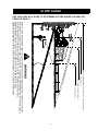
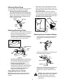
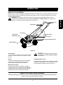
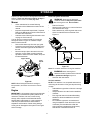
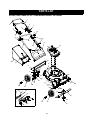
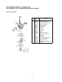
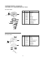
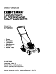
1
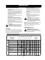
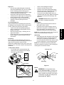
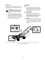
SAFETY
Owner’s Manual
ASSEMBLY
19” Mulching/Rear Discharge
OPERATION
PUSH LAWN MOWER
MAINTENANCE
Model No.
247.388240
ADJUSTMENTS
STORAGE
ES
Printed in U.S.A.
ESPANÓL
Sears, Roebuck & Co., Hoffman Estates, IL 60179, U.S.A.
PARTS LIST
CAUTION: Before using this product,
read this manual and follow all Safety
Rules and Operating Instructions.
770-10185A
(1/99)
TABLE OF CONTENTS
Content
Page
Content
Page
Warranty Information ................................... 2
Service & Adjustment..................................... 15
Safe Operation Practices ............................. 3
Storage .......................................................... 17
Slope Gauge ................................................ 6
Trouble-Shooting ........................................... 19
Assembly ..................................................... 7
Parts List........................................................ 20
Operation ..................................................... 9
Espanól.......................................................... 26
Maintenance .................................................. 12
WARRANTY INFORMATION
Two-Year Warranty on Craftsman Lawn Mower
For two years from the date of purchase, when this Craftsman lawn mower is maintained, lubricated, and tuned
up according to the instructions in the owner’s manual, Sears will repair, free of charge, any defects in material or
workmanship. If this lawn mower is used for commercial or rental purposes, this warranty applies for only 90 days
from the date of purchase.
This warranty does not cover:
1. Expendable items which become worn during normal use, such as rotary mower blades, blade adapters,
belts, air cleaners and spark plug.
2. Repairs necessary because of operator abuse or negligence, including bent crankshafts and the failure to
maintain equipment according to the instructions contained in the owner’s manual.
WARRANTY SERVICE IS AVAILABLE BY RETURNING THE CRAFTSMAN LAWN MOWER TO THE
NEAREST SEARS SERVICE CENTER IN THE UNITED STATES. THIS WARRANTY APPLIES ONLY WHILE
THIS PRODUCT IS IN USE IN THE UNITED STATES.
This warranty gives you specific legal rights, and you may also have other rights which vary from state to state.
Sears, Roebuck And Co., D/817WA, Hoffman Estates, IL 60179
ACCESSORIES
These accessories were
available when the lawn
mower was purchased. They
are also available at most
Sears retail outlets, and
service centers. Most Sears
stores can order repair parts
for you when you provide the
model number of your lawn
mower.
Spark Plug
Muffler
Safety
Glasses
Engine Oil Stabilizer
PRODUCT SPECIFICATIONS
Horsepower:
4.0
Engine Oil
21 oz. SAE 30 oil
Fuel Capacity:
1.5 quarts
Spark Plug
J19LM
Gap .030 inches
Gas Can
Wheels
Blade
Grass Catcher
Please record model number, serial number, and
date of purchase here for future reference. You will
find this information on the model plate located on
the cutting deck of your mower.
Model Number .........................................................
Serial Number...........................................................
Date of Purchase ......................................................
2
This symbol points out important safety instructions which, if not followed, could endanger the personal safety and/or property of yourself and others. Read and follow all instructions in this manual before
attempting to operate your lawn mower. Failure to comply with these instructions may result in personal
injury. When you see this symbol—heed its warning.
Your lawn mower was built to be operated according to the rules for safe operation in this
manual. As with any type of power equipment, carelessness or error on the part of the operator
DANGER:
can result in serious injury. If you violate any of these rules, you may cause serious injury to
yourself or others.
This unit is equipped with an internal combustion engine and should not be used on or near any unimproved
forest-covered, brush-covered or grass-covered land unless the engine’s exhaust system is equipped with a
spark arrester meeting applicable local or state laws (if any). If a spark arrester is used, it should be
maintained in effective working order by the operator.
In the State of California the above is required by law (Section 4442 of the California Public Resources
Code). Other states may have similar laws. Federal laws apply on federal lands. A spark arrester for the
muffler is available through your nearest Sears Authorized Service Center (See the REPAIR PARTS section
of this manual.)
WARNING: The engine exhaust from this product contains chemicals known to the State of California to
cause cancer, birth defects or other reproductive harm.
GENERAL OPERATION
•
•
•
•
•
Read this owner’s guide carefully in its entirety
before attempting to assemble this machine.
Read, understand, and follow all instructions on
the machine and in the manual(s) before
operation. Be completely familiar with the controls
and the proper use of this machine before
operating it. Keep this manual in a safe place for
future and regular reference, and for ordering
replacement parts.
Your rotary mower is a precision piece of power
equipment, not a plaything. Therefore, exercise
extreme caution at all times. Your unit has been
designed to perform one job: to mow grass. Do not
use it for any other purpose.
Never allow children under 14 years old to operate
a power mower. Children 14 years old and over
should only operate mower under close parental
supervision. Only responsible individuals who are
familiar with these rules of safe operation should
be allowed to use your mower.
Keep the area of operation clear of all persons,
particularly small children and pets. Stop engine
when they are in the vicinity of your mower to help
prevent blade contact or thrown object injury.
Although the area of operation should be
completely cleared of foreign objects, an object
may have been overlooked and could be
accidentally thrown by the mower in any direction
and cause serious personal injury to the operator
or any others allowed in the area.
•
•
•
•
•
3
Thoroughly inspect the area where the equipment
is to be used. Remove all stones, sticks, wire,
bones, toys and other foreign objects which could
be picked up and thrown by the mower in any
direction and cause serious personal injury to the
operator or any others allowed in the area. Plan
your mowing pattern to avoid discharge of material
toward roads, sidewalks, bystanders and the like.
To help avoid a thrown object’s injury, keep
children, bystanders and helpers at least 75 feet
from the mower while it is in operation.
Always wear safety glasses or safety goggles
during operation or while performing an adjustment
or repair, to protect eyes from foreign objects that
may be thrown from the machine in any direction.
Wear sturdy, rough-soled work shoes and closefitting slacks and shirts. Shirts and pants that cover
the arms and legs and steel-toed shoes are
recommended. Do not wear loose fitting clothes or
jewelry. They can be caught in moving parts. Never
operate a unit in bare feet, sandals, slippery or light
weight (e.g. canvas) shoes.
Do not put hands or feet near or under rotating
parts. Keep clear of discharge opening at all times
as the rotating blade can cause injury.
Many injuries occur as a result of the mower being
pulled over the foot during a fall. Do not hang on to
the mower if you are falling; release the handle
immediately.
Never pull the mower toward you while you are
walking. If you must back the mower away from a
SAFETY
SAFE OPERATION PRACTICES
•
•
•
•
•
•
•
•
•
•
•
•
•
as shown on the slope gauge (page 6), do not operate this
unit on that area or serious injury could result.
wall or obstruction first look down and behind, and
then follow these steps:
a. Step back from the mower to fully extend your
arms.
b. Be sure you are well balanced with sure
footing.
c. Pull the mower back slowly, no more than half
way toward you.
d. Repeat these steps as needed.
Do not operate the mower while under the
influence of alcohol or drugs.
Do not engage the self-propelled mechanism on
units so equipped while starting engine.
The blade control handle is a safety device. Never
attempt to bypass its operation. Doing so makes
the safety device inoperative and may result in
personal injury through contact with the rotating
blade. The blade control handle must operate
easily in both directions and automatically return
to the disengaged position when released.
Never operate the mower in wet grass. Always be
sure of your footing. A slip and fall can cause
serious personal injury. Keep a firm hold on the
handle and walk, never run. If you feel you are
losing your footing, RELEASE THE BLADE
CONTROL HANDLE IMMEDIATLEY and the
blade will stop rotating within three seconds.
Mow only in daylight or good artificial light.
Stop the blade when crossing gravel drives, walks
or roads.
If the equipment should start to vibrate
abnormally, stop the engine and check
immediately for the cause. Vibration is generally a
warning of trouble.
Shut the engine off and wait until the blade comes
to a complete stop before removing the grass
catcher or unclogging the chute. The cutting
blade continues to rotate for a few seconds after
the engine is shut off. Never place any part of the
body in the blade area until you are sure the blade
has stopped rotating.
Never operate mower without proper guards,
grass catcher, plates or other safety protective
devices in place.
Muffler and engine become hot and can cause a
burn. Do not touch.
Do not adjust the throttle control with the engine
running.
Only use accessories approved for this machine
by the manufacturer. Read, understand, and
follow all instructions provided with the approved
accessory.
If situations occur which are not covered in this
manual, use care and good judgment. Contact
your dealer for assistance.
DO:
•
•
•
•
Mow across the face of slopes; never up and
down. Exercise extreme caution when changing
direction on slopes.
Watch for holes, ruts, hidden objects, or bumps.
Tall grass can hide obstacles.
Always be sure of your footing. A slip and fall can
cause serious personal injury. If you feel you are
losing your balance release the blade control
handle immediately and the blade will stop in less
than 3 seconds.
ON MODELS WITH CASTER WHEELS: Lock
both front wheels so they do not pivot while
mowing on the face of slopes. To turn the mower,
depress the handle and raise the front wheels
slightly.
DO NOT:
•
•
•
•
Do not mow near drop-offs, ditches or
embankments. The operator could lose footing or
balance.
Do not mow slopes greater than 15 degrees as
shown on the slope gauge.
Do not mow on wet grass. Reduced footing could
cause slipping.
ON MOWERS WITH CASTER WHEELS: Do Not
mow on slopes with casters unlocked since the
mower has a tendency to drift down hill.
Children
Tragic accidents can occur if the operator is not alert to the
presence of children. Children are often attracted to the
mower and the mowing activity. Never assume that
children will remain where you last saw them.
•
Keep children out of the mowing area and under
the watchful care of a responsible adult other than
the operator.
•
Be alert and turn mower off if a child enters the
area.
•
Before and while moving backwards, look behind
and down for small children or other objects.
•
Never allow children under age 14 to operate the
mower. Children 14 years of age and above
should read and understand the operation
instructions and safety rules in this manual.
•
Use extreme care when approaching blind
corners, shrubs, trees, or other objects that may
obscure your vision of a child or hazard.
Service
•
•
•
Slope Operation
For your safety, use the slope gauge included as part of
this manual to measure slopes before operating this unit on
a slope or hilly area. If the slope is greater than 15 degrees
4
Use extreme care in handling gasoline and other
fuels. They are extremely flammable and the
vapors are explosive.
Use only an approved gasoline container.
Never remove gas cap or add fuel while the
engine is running. Allow engine to cool at least
two minutes before refueling.
•
•
•
•
•
•
•
•
•
•
•
Replace gasoline cap securely and wipe off any
spilled gasoline before starting the engine as it
may cause a fire or explosion.
Extinguish all cigarettes, cigars, pipes and other
sources of ignition.
Never refuel machine indoors because flammable
vapors will accumulate in the area.
Never store the machine or fuel container inside
where there is an open flame or spark such as a
gas water heater, space heater, or furnace.
Never run an engine inside a closed area.
To reduce fire hazard, keep mower free of grass,
leaves, or other debris build-up. Clean up oil or
fuel spillage. Allow mower to cool at least 5
minutes before storing.
Before cleaning, repairing, or inspecting, make
certain the blade and all moving parts have
stopped. Disconnect the spark plug wire, and
keep the wire away from the spark plug to prevent
accidental starting.
Check the blade and engine mounting bolts at
frequent intervals for proper tightness. Also,
visually inspect blade for damage (e.g., bent,
cracked or worn). Replace with blade which
meets original equipment specifications listed in
this manual.
Keep all nuts, bolts, and screws tight to be sure
the equipment is in safe working condition.
Never tamper with safety devices. Check their
proper operation regularly.
•
•
•
•
After striking a foreign object, stop the engine,
remove the wire from the spark plug, and
thoroughly inspect the mower for any damage.
Repair the damage before starting and operating
the mower.
Never attempt to make a wheel or cutting height
adjustment while the engine is running.
Grass catcher components are subject to wear,
damage and deterioration, which could expose
moving parts or allow objects to be thrown. For
safety protection, frequently check components
and replace with manufacturer’s recommended
parts, when necessary.
Mower blades are sharp and can cut. Wrap the
blade(s) or wear gloves, and use extra caution
when servicing them.
Do not change the engine governor setting or
overspeed the engine. Excessive engine speeds
are dangerous.
YOUR RESPONSIBILITY
Restrict the use of this power machine to
persons who read, understand and follow the
warnings and instructions in this manual and
on the machine.
Following are representations of the safety labels on your lawn mower. Maintain safety while operating the mower.
Please have the part number ready when re-ordering safety labels.
SAVE THESE INSTRUCTIONS FOR FUTURE REFERENCE.
5
SLOPE GUAGE
USE THIS PAGE AS A GUIDE TO DETERMINE SLOPES WHERE YOU MAY NOT
OPERATE SAFELY:
FOL
DO
N
D
OTT
E
D LI
N
15°
SIGHT AND HOLD THIS LEVEL WITH A VERTICAL TREE
A POWER POLE
A 15
° SL
OPE
OR A FENCE POST
A CORNER OF A BUILDING
E, RE
PRE
S
E
N
TING
WARNING
Do not mow on inclines with a slope in excess of 15 degrees (a rise of approximately 2-1/2 feet every 10 feet).
A riding mower could overturn and cause serious injury. If operating a walk-behind mower on such a slope, it
is extremely difficult to maintain your footing and you could slip, resulting in serious injury.
Operate RIDING mowers up and down slopes, never across the face of slopes.
Operate WALK-BEHIND mowers across the face of slopes, never up and down slopes.
6
ASSEMBLY
•
•
•
•
B
Upper Handle
A
Remove staples, break glue on top flaps, or cut
tape at carton end and peel along top flap to
open carton.
Remove loose parts if included with unit (i.e.,
owner's manual, etc.).
Cut along dotted lines and lay carton down flat.
Remove packing material. Roll unit out of
carton. Check carton thoroughly for loose parts.
Note: Make sure not to crimp the cable while
removing loose parts or the unit from the carton.
Lower Handle
IMPORTANT: This unit is shipped without gasoline
or oil in the engine. Be certain to service engine with
gasoline and oil before operating your mower.
Figure 2
For shipping purposes, the hairpin clip is placed in the
outer hole of the weld pin on the lower handle.
•
Remove the hairpin clip from the outer hole of
the weld pin. See Figure 3.
NOTE: Reference to right or left hand side of the
mower and/or front or behind the mower is observed
from the operating position.
Loose Parts
a.
b.
c.
d.
Owner’s Manual
A Bottle of Engine Oil
Parts for Grass Bag: Frame, Bag
Discharge Chute
Hairpin
Clip
Tools Required
Weld Pin
a. Pair of Pliers
b. Funnel
Outer Hole on
Weld Pin
Disconnecting Spark Plug
•
•
Figure 3
Before setting up your lawn mower, disconnect
the spark plug wire from the spark plug, and
ground it against the engine. See Figure 1.
Attach rubber boot to a bolt on the engine to
ground as shown below.
Spark Plug
Wire
Lower
Handle
•
•
•
Rubber Boot
Spark Plug
Using a pair of pliers, insert the hairpin clip into
the inner hole in the weld pin. See Figure 3.
Repeat on other side.
Raise the upper handle in the direction B shown
in Figure 2. Tighten the wing nuts which are
already on the handle.
Attach control cable to the lower handle with the
cable tie already on the lower handle. Pull tight
the cable tie and cut off extra. See Figure 4.
Cable Tie
Figure 1
Assembling Handle
•
Raise lower handle in direction A shown in
Figure 2. It should snap into place.
Note: Make sure to route the cable inside the lower
handle. Also do not crimp the cable while lifting the
handle up
Figure 4
7
ASSEMBLY
Removing Unit From Carton
Attaching Starter Rope
•
The rope guide is already attached to the right side of
the upper handle of your mower. See Figure 5.
• With the spark plug wire disconnected and
grounded, hold the blade control handle against the
upper handle, and pull starter rope out of the engine.
• Slip the rope through the rope guide as shown in
Figure 5. Tighten the wing nut holding the rope
guide to the upper handle.
Recoil
Starter
•
Place bag over frame (black plastic side is the
bottom of bag). Slip the openings in the side of
the plastic channel on bag over the hooks on the
grass catcher frame.
Secure bag to frame by working the plastic
channels on bag over frame as shown in Figure
7. All of the plastic channels except center top of
bag attach from the outside of bag. Center top of
bag attaches from the inside of bag.
Wing Nut
Hook
Rope
Guide
Figure 5
Frame
Attaching Discharge Chute
•
•
Plastic
Channels
Grass
Bag
Figure 7
There is a groove 2” from the left end of the rod.
Bend and snap off approximately 2” of the rod
with a pair of vise grips. See Figure 6.
Insert push cap, provided with the chute rod,
onto the end of the rod which you just snapped
off. Tap on with a hammer. See Figure 6.
Attaching Grass Catcher to Mower
•
Groove
Lift the chute door on the mower. Remove the
mulching plug or the discharge chute. See
Figure 8.
Mulching
Plug
Rear Discharge
Door
Chute
Rod
Figure 8
•
Push
Cap
Holding the grass bag firmly, place the bag on
the mower as shown in Figure 9.
Discharge
Chute
Hook
Figure 6
•
•
To attach discharge chute: Lift the discharge
door and place the ends of the chute rod into
the slot on each handle bracket assembly.
Release the rear discharge door.
To remove discharge chute: Lift the rear
discharge door of the mower. Lift the discharge
chute up and outwards and pull it out of the
slots on the handle bracket assemblies.
Release the rear discharge door.
Grass Catcher
Slot
Figure 9
•
Assembling Grass Catcher
Place hooks, located on two sides of the grass
catcher frame, in the slots on the handle
brackets. See Figure 9. Release the chute
door.
Warning: Never operate the mower unless
the grass catcher frame is firmly seated on
the chute door pivot rod, and the rear
discharge door rests firmly on top of the
grass catcher.
NOTE: Make certain bag is turned right side out
before assembling (warning label will be on the
outside).
8
OPERATION
Know Your Lawn Mower
Blade Control
Handle
Recoil Starter
Oil Fill Plug
Grass Catcher
Front Height
Adjustment Lever
Gas Tank Cap
Rear Height Adjustment Lever
Spark Plug Wire
Primer
Figure 10
Recoil Starter
The recoil starter is attached to the handle. Stand
behind the unit and pull the recoil starter to start
the unit.
WARNING: This blade control mechanism
is a safety device. Never attempt to bypass
its operations.
Primer
The primer is used to pump gas into the carburetor.
Use it to start a cold engine, but do not use it to
restart a warm engine after short shutdown.
Height Adjustment Lever
These levers are located on each wheel and are used
to adjust the cutting height. All four levers have to be at
the same relative position to ensure uniform cut.
Blade Control Handle
The blade control handle is located on the upper
handle of the mower. The blade control handle must
be depressed in order to operate the unit. Release
blade control handle to stop engine and blade.
Meets CPSC Blade Safety Standards
Craftsman Walk-Behind Lawn Mowers conform to the safety standards of the American National Standards Institute
and the U.S. Consumer Product Safety Commission.
9
OPERATION
Read this owner’s manual and safety rules before operating your lawn mower. Compare the illustrations in Figure
10 with your lawn mower to familiarize yourself with the location of various controls and adjustments. Save this
manual for future reference.
WARNING: The operation of any lawn mower can result in foreign objects being thrown into the
operator’s eyes and causing severe eye damage. Always wear safety glasses while operating the
mower, or while performing any adjustments or repairs on it.
Stopping Engine
Starting Engine
•
(Refer to Figure 11.)
•
Release blade control handle to stop the
engine and the blade.
Disconnect spark plug wire and move away
from spark plug to prevent accidental starting.
WARNING: Be sure no one other than the
operator is standing near the lawn mower
while starting or operating.
WARNING: Before using your lawn mower,
again refer to the safety rules on pages 3-5
of this manual. Always be careful.
•
Gas And Oil Fill-Up
WARNING: Never run engine indoors or in
enclosed, poorly ventilated areas. Engine
exhaust contains carbon monoxide, an
odorless and deadly gas.
Engine Oil
Only use high quality detergent oil rated with API
service classification SF, SG or SH. Select the oil’s
viscosity grade according to your expected operating
temperature. Follow the chart below.
o
32 F
Colder
5W30
WARNING: Keep hands, feet, hair and
loose clothing away from any moving parts
on engine and lawn mower.
Warmer
•
SAE 30
Oil Viscosity Grade Chart
•
•
•
Attach spark plug wire to spark plug. Make
certain the metal cap on the end of the spark
plug wire is fastened securely over the metal tip
on the spark plug.
Use SAE30 oil; do not use 10W40 oil.
Fill oil sump and check the oil level as follows:
a. Position the mower on level ground.
b. Clean area around oil fill plug.
c. Remove oil fill plug and dipstick.
d. Wipe dipstick clean, insert it into oil fill hole
and tighten securely.
e. Remove dipstick and check oil level. If the
oil is not upto FULL mark on the dipstick,
pour recommended oil through the oil fill
and check the level again.
Install oil fill plug and dipstick, tighten securely.
•
Push primer three times. Wait about two
seconds between each push. In cold weather
around 55o F or below, prime five times. Do not
prime to restart a warm engine after a short
shutdown.
Hold control handle against the upper handle.
Grasp recoil starter and pull rope out slowly
until engine reaches the start of compression
cycle (rope will pull slightly harder at this point).
See Figure 11 inset. Let the rope rewind slowly.
Hold handles firmly
NOTE: Although multi-viscosity oils (5W30, 10W30,
etc.) improve starting in cold weather, these
multiviscosity oils will result in increased oil
consumption when used above 32oF. Check the oil
level more frequently to avoid possible engine
damage from running low on oil.
Check/fill oil
Pull recoil starter
Fill gasoline
Gasoline
WARNING: Never fill fuel tank indoors, or
when engine is running or hot. Do not
smoke when filling fuel tank.
•
•
•
Clean area around gas tank cap. For location,
see Figure 10. Remove cap.
Use a funnel to prevent spillage.
Pour approximately 1.5 quarts of fresh, regular
grade, unleaded gasoline slowly to the fuel tank.
Attach spark
plug wire
Prime 3 times
IMPORTANT: Never mix engine oil with gasoline.
•
Fill tank to 1/2” below the bottom of the filler
neck. Wipe any fuel spillage. Do not fill fuel tank
completely. Provide space for fuel expansion.
Figure 11
10
•
Pull rope with a rapid, continuous, full arm
stroke. Keeping a firm grip on the recoil starter,
let the rope return to the starter slowly.
•
•
Using Your Lawn Mower
Your mower is designed to operate as a mulching or a
side discharge unit.
•
For converting from a mulcher to a side
discharge unit, refer to instructions on page 8.
Do not operate mower without the mulching
deflector or the grass catcher properly
installed and tightly secured.
•
Be sure that lawn is clear of stones, sticks,
wire, or other objects which could damage lawn
mower or engine. Such objects could be
accidently thrown by the mower in any direction
and cause serious personal injury to the
operator and others.
•
For best results, do not cut wet grass because
it tends to stick to the underside of the mower,
preventing proper discharge of grass clippings,
and could cause you to slip and fall. New grass,
thick grass or wet grass may require a
narrower cut. Blade speed should be adjusted
to the condition of the lawn.
•
The best mowing pattern is one that allows the
clippings to discharge towards the uncut part of
the lawn. This permits recutting of the clippings
to further pulverize them. When cutting high
weeds, discharge towards cut portion, then
recut at right angles to first direction.
•
For a healthy lawn, always cut off one-third or
less of the total length of the grass. Lawn should
be cut in the fall as long as there is growth.
•
This mower is designed to be operated at full
throttle to give you the best cut and do the
most effective job of bagging the clippings.
•
•
Operate the mower till the grass catcher bag is
full, or the job has been completed whichever is
earlier.
Stop the engine completely by releasing the
blade control handle. Make sure that the unit
has come to a complete stop and the blade has
stopped rotating. Empty the grass catcher bag
as follows.
Lift the discharge door and pull the grass bag
away from the mower as shown in Figure 12.
Holding the bag firmly, carry the bag away from
the mower. Dispose off the clippings
appropriately.
Chute Door
Bag Handle
Hold bag with
clippings firmly
WARNING: If the mower strikes a foreign
object, stop the engine. Remove spark plug
wire from spark plug and thoroughly inspect
the mower for any damage. Repair the
damage before restarting the mower.
Extensive vibration during operation is an
indication of equipment damage.
Figure 12
Height Adjustment
Refer to height adjustments section of this manual on
page 16 for instruction on how to adjust the cutting
height and the handle height.
For best results in mowing, keep the cutting height
position high until it is determined which height is best
for your lawn.
Using Grass Catcher
You can use the grass catcher bag to collect clippings
while operating the mower.
•
Attach the grass catcher to the mower following
instructions on page 8 of this manual.
11
MAINTENANCE
•
•
General Recommendations
•
•
•
•
•
•
•
Always observe safety rules when performing
any maintenance.
The warranty on this lawn mower does not cover
items that have been subjected to operator abuse
or negligence. To receive full value from the
warranty, operator must maintain the lawn mower
as instructed in this manual.
Changing of engine governed speed will void
engine warranty.
Some adjustments will have to be made
periodically to maintain your unit properly.
All adjustments in the Service and Adjustments
section of this manual should be checked at
least once each season.
Follow the maintenance schedule given below.
Periodically check all fasteners and make sure
these are tight.
Disconnect spark plug wire.
Drain the gasoline from the lawn mower, or
place a piece of plastic under the gas cap.
Tip the mower so that it rests on the housing.
Keep the side with the air cleaner facing up.
Hold it firmly.
Scrape clean the underside of the deck with a
suitable tool.
Put the mower back on its wheels on the
ground. If you had put plastic under the gas
cap, make sure to remove it now.
•
•
•
WARNING: Never tip the mower more
than 90 degrees and do not leave the
mower tipped for any length of time. Oil
can drain into the upper part of the engine
causing a starting problem.
NOTE: We do not recommend using a garden hose to
clean mower unless the muffler, air filter and
carburetor are covered to keep water out. Water in
engine can shorten engine life.
WARNING: Always stop the engine and
disconnect the spark plug wire before
performing any maintenance or adjustments.
Engine Maintenance
Cleaning
WARNING: Always stop engine,
The underside of the mower deck should be cleaned
after each use to prevent any buildup of grass clippings,
leaves, dirt , or other debris. If this debris is allowed to
accumulate, it will result in rust and corrosion.
disconnect spark plug wire, and move it
away from spark plug before performing any
adjustments or repairs.
PRODUCT
Lubricate casters
Lubricate blade control
Clean deck
Change oil
Replace air filter
Clean engine
Check spark plug
Check spark arrester (if any)
12
as
Be
f or
e
es
se
tor
ag
on
s
ur
ea
On
c
Ev
er
y1
00
ho
ou
0h
y5
er
Ev
Lubricate wheels
Blade care
ENGINE
rs
rs
ou
5h
ou
y2
er
oh
Ev
tw
Fir
st
t er
Af
MAINTENANCE
SCHEDULE
ea
ch
us
rs
e
Customer Responsibilities
SERVICE
DATES
Engine Oil
•
Only use high quality detergent oil rated with
API service classification SF, SG or SH. Select
the oil’s viscosity grade according to your
expected operating temperature. Refer to page
10 of this manual for viscosity chart.
•
Stop engine and wait several minutes before
checking oil level. With engine on level ground,
the oil must be to FULL mark on dipstick .
•
Change engine oil after the first five hours of
operation, and every twenty-five hours
thereafter.
•
•
•
To Change Engine Oil
Change oil after first two operating hours and every
25 operating hours thereafter. Drain oil while engine
is warm. Follow the instructions given below.
•
Tip the mower with the spark plug facing up.
•
Place a container under the dipstick. Pull the
dipstick out of oil fill.
•
Drain the oil sump empty, collecting oil in an
approved container.
•
Fill oil sump with 21 ounces of fresh SAE 30 oil.
Refer to page 10 of this manual for oil fill-up
instructions.
Clean Engine
•
Clean engine periodically. Remove dirt and
debris with a cloth or brush.
•
Frequently remove grass clippings, dirt and
debris from cooling fins, air intake screen and
levers and linkage. This will help ensure
adequate cooling and correct engine speed.
•
Clean cover and flange thoroughly.
Insert the new filter into the cover.
Place the cover and the filter against flange
with tab on the cover inserted into lower left
corner of slot in flange. See Figure 13.
Push cover firmly against flange and turn it
clockwise as far as it will go. Make sure that the
retainers are locked around the flange. See
Figure 13.
WARNING: Never run the engine without
air cleaner completely assembled.
Spark Plug
•
Clean spark plug and reset gap to .030" at least
once a season or every 50 hours of operation.
See Figure 14. Spark plug replacement is
recommended at the start of each season. Refer
to engine parts list for correct spark plug type.
Air Cleaner
The air cleaner prevents damaging dirt, dust, etc.,
from entering the carburetor and being forced into the
engine and is important to engine life and
performance. Replace filter once a year or every 100
operating hours, more often if used in extremely dusty
conditions.
NOTE: Do not sandblast spark plug. Spark plug
should be cleaned by scraping or wire brushing and
washing with a commercial solvent.
To Service Air Cleaner:
•
Turn air filter cover counterclockwise and
remove the cover and filter from the flange.
See Figure 13. Discard filter.
Turn to
remove
Turn to
tighten
Feeler gap .030”
Spark Plug
Air Cleaner
Flange
Filter Retainer
Figure 14
Muffler
Cover
WARNING: Do not operate the lawn
mower without a muffler, or tamper with
the exhaust system. Damaged mufflers or
spark arresters could create a fire hazard.
Temperature of muffler and nearby areas
may exceed 150o F(65oC).
Slot
Tab
Retainer
Figure 13
13
MAINTENANCE
NOTE: Do not clean with a forceful spray of water as
water could contaminate the fuel system.
Blade Care
Lubrication
Periodically inspect the blade adapter for cracks,
especially if you strike a foreign object. Replace when
necessary.
Wheels
•
Lubricate the wheels at least once a season
with light oil or engine oil. Also, if the wheels are
removed for any reason, lubricate the surface
of the axle bolt and the inner surface of the
wheel with light oil.
WARNING: When inspecting the cutting
blade, protect hands by using heavy
gloves or a rag to grasp the cutting
blade.
•
•
Blade Control Handle
•
Lubricate the pivot points on the blade control
handle and the brake cable at least once a
season with light oil. The blade control handle
must operate freely in both directions. For
complete lubrication chart, see Figure 15.
Disconnect spark plug wire from spark plug.
Turn mower on its side making sure that the air
filter and the carburetor are up to check the
blade. If the blade needs to be serviced, refer
to the instructions on blade care in the “Service
& Adjustments” section of this manual.
Chute Deflector
•
Lubricate the torsion spring and the pivot point
on each end of the chute deflector using a light
oil. This will prevent rusting and ensure that the
deflector, which is a safety device, can always
work properly.
Figure 15
Lubricate
Lubricate
Lubricate
NOTE: For sake of clarity, illustrations in the insets represent view from another perspective rather than from the operating position.
Figure 15: Lubrication Chart
14
SERVICE & ADJUSTMENTS
Servicing Blade
To Sharpen Blade:
The blade can be sharpened with a file or on a grinding
wheel. Do not attempt to sharpen while on the mower.
•
Follow the original angle of grind as a guide.
Make sure that each cutting edge receives an
equal amount of grinding to prevent an
unbalanced blade.
NOTE: An unbalanced blade will cause excessive
vibration when rotating at high speeds, may cause
damage to the mower and could break, causing
personal injury.
•
Test the blade by balancing it on a round shaft
screwdriver or a blade balancer. See Figure 17.
•
If the blade is not balanced, remove metal from
the heavy side until it balances evenly.
To Remove Blade
•
Remove the bolt and blade bell support which
hold the blade and adapter to the engine
crankshaft. See Figure 16.
•
Remove the blade and adapter from the
crankshaft.
To Replace Blade:
•
Before reinstalling the blade and the blade
adapter to the unit, lubricate the engine
crankshaft and the inner surface of the blade
adapter with light oil.
•
Install the blade adapter on the crankshaft with
the “star” away from the engine. See Figure 16.
1. Insert screw driver through hole
Blade Adapter
Crankshaft
2. Blade should be parallel to ground
Screw
Blade
Driver
Blade
Blade Bell
Support
Hex Bolt
Figure 17
Engine Adjustments
WARNING: Do not make unnecessary
adjustments on the engine. Factory settings
are satisfactory for most conditions.
If any adjustments are made to the engine
while the engine is running, keep clear of all
moving parts. Be careful of heated
surfaces and muffler. Keep your hands
away from these parts.
Figure 16
•
•
•
•
Place the new blade with the side marked
bottom (or with part number) facing away from
the adapter.
Place the bell support next. Make sure to align
the tabs in the holes of the blade with the hole in
the bell support.
Insert the hex bolt through the blade assembly.
Figure 16 shows the correct order of assembly.
Use block of wood to hold blade again while you
tighten the bolt clockwise. Follow the
recommended torque for the bolt which is 450600 in.-lbs.
Carburetor
The carburetor has been pre-set at the factory and
should not require adjustment.
•
If the engine on your mower does not operate
properly due to suspected carburetor problems,
take your lawn mower to your nearest SEARS
service center.
•
Engine performance may be affected in altitudes
above 4000 feet. To improve engine
performance, install a high altitude adjustment
kit, available at the SEARS service center.
NOTE: A dirty air cleaner will cause an engine to run
rough. Be certain air cleaner is clean and attached to
the carburetor.
IMPORTANT: The bolt, used to secure the blade to
the engine, is specially heat-treated. Do not
substitute. To order replacement bolt, refer to the
Repair Parts section of this manual.
WARNING: To ensure safe operation of
your unit, all nuts and bolts must be
checked periodically for correct tightness.
15
ADJUSTMENTS
Ground
Engine Speed
Adjusting Cutting Height
WARNING: Overspeeding engine above
IMPORTANT: All wheels must be placed in the same
relative position.
the factory setting can be dangerous. Do not
attempt to increase engine speed or it may
result in personal injury. Changing of engine
governed speed will void engine warranty.
•
•
Raise the mower wheels for low cut and lower the
wheels for high cut. For rough or uneven lawns,
move the height adjustment lever to a higher
position. This will help stop scalping of the
grass.
There is an adjusting plate and thumb lever at each
wheel position to adjust the cutting height. Each
adjusting plate has nine height positions. Height of cut
will change if you move the thumb lever from one hole
to another.
•
Simply depress the lever towards wheel and
move the wheel and lever assembly to the
desired position. See Figure 19. All wheels
must be placed in the same relative position for
uniform cutting height.
•
For rough or uneven lawns, move the height
adjustment handles to positions which will give
a higher cutting height. Both front and rear
handles must be placed in the same relative
position.
If you believe the engine is running too fast or
too slow, take your lawn mower to the nearest
SEARS service center.
Adjusting Handle Height
Your mower is shipped with the handle in the higher
height position. To lower the handle height, proceed
as follows.
•
Remove the starter rope from the rope guide.
•
Remove the upper handle by removing the hand
knobs and carriage bolts. Lay the upper handle
out of the way, being careful not to bend or kink
the cable.
•
Remove the hairpin clip from the weld pin on the
handle bracket on each side of the lower handle.
See Figure 18 inset. Press out on the legs of the
lower handle. Remove lower handle from the
mower.
•
Turn the lower handle around so the notch on
the bottom of the lower handle is facing forward
as shown in Figure 18. Reassemble, placing the
bottom hole on the handle over the weld pin in
the handle mounting bracket.
•
Reassemble the upper handle to the lower
handle.
•
Place the hairpin clips in the inner holes in the
weld pins and attach the starter rope as
instructed in the Assembly section. See Figure
18 inset.
Height Adjustment
Lever
Notch
Lower
Handle
Hairpin
Clip
Figure 19
Lower
Handle
Figure 18
16
STORAGE
Prepare your lawn mower for storage at the end of the
season or if the unit will not be used for 30 days or
more. Store the mower in a clean, dry area.
Drain fuel system & carburetor
WARNING: Drain fuel into approved
container outdoors away from open flame.
Be sure engine is cool. Do not smoke.
Mower
•
Clean underside of the mower following
instructions in the Maintenance section of this
manual.
•
Inspect and replace/sharpen blade, if required.
Refer to the Maintenance section of this manual
for blade care instructions.
•
Lubricate mower following the lubrication chart
on page 14 of this manual.
You can fold your mower’s handle for convenient
storage as shown in Figure 20. Follow the steps
below to fold the handle.
•
Remove the starter rope from the rope guide.
•
Loosen the two hand knobs on the sides of the
handle, and let the upper handle fold down to
the rear.
•
Move the hairpin clips to the outer hole in the
weld pins on the handle mounting brackets.
•
Spread the sides of the lower handle, and push
it forward and down.
•
•
•
Drain the fuel tank.
Start the engine and let it run until the fuel lines
and carburetor are empty.
Drain carburetor by removing bowl drain screw
which is located below the carburetor. See
Figure 21.
Upper Handle
Carburetor
Lower
Handle
Bowl Drain
Figure 21
Note: Do not drain carburetor if using fuel stabilizer.
WARNING: Never use engine or
•
Use fresh fuel next season.
Use fuel stabilizer
Figure 20
NOTE: Fuel stabilizer is an acceptable alternative in
minimizing the formation of fuel gum deposits during
storage.
NOTE: When folding the handle for storage or
transportation, be careful not to bend or kink the
cable.
•
Engine
•
IMPORTANT: It is important to prevent gum deposits
from forming in essential fuel system parts such as
carburetor, fuel filter, fuel hose, or tank during
storage. Also, experience indicates that alcohol
blended fuels (called gasohol or using ethanol or
methanol) can attract moisture which leads to
separation and formation of acids during storage.
Acidic gas can damage the fuel system of an engine
while in storage.
•
•
17
Add stabilizer to gasoline in fuel tank or storage
container.
Always follow the mix ratio found on stabilizer
container.
Run engine at least 10 minutes after adding
stabilizer to allow the stabilizer to reach the
carburetor.
Do not drain the gas tank and carburetor if
using fuel stabilizer. Drain all the oil from the
crankcase (This should be done after the
engine has been operated and is still warm)
and refill the crankcase with fresh oil.
STORAGE
carburetor cleaner products in the fuel tank
or permanent damage may occur.
Oil cylinder bore
After you have drained the fuel tank, protect the
inside of the engine as follows:
•
Remove spark plug, pour approximately one
ounce (30 ml) of engine oil into spark plug hole,
and crank slowly to distribute oil.
Clean engine
•
Clean engine and remove any grass clippings,
dirt, or chaff from the exterior of the engine.
•
Remove any dirt or debris from cooling fins, air
intake screen, levers, and linkage.
OTHER
WARNING: Avoid spray from spark plug
•
hole when cranking the engine slowly.
•
•
Replace spark plug; do not connect spark plug wire.
Change oil
•
Change oil if it has not been changed in the last
three months. For instructions on how to
change oil refer to the Maintenance section of
this manual.
Do not store gasoline from one season to
another.
Replace your gasoline can if it starts to rust.
Rust and/or dirt in the gasoline will cause
problems. Store unit in a clean, dry area. Do not
store next to corrosive materials, such as
fertilizer.
NOTE: If storing in an unventilated or metal storage
shed, be certain to rustproof the equipment by coating
with a light oil or silicone.
18
TROUBLE-SHOOTING
PROBLEM
POSSIBLE CAUSE
CORRECTIVE ACTION
Engine fails to start
1. Blade control handle disengaged
2. Spark plug wire disconnected
3. Throttle control lever not in starting position
4. Fuel tank empty, or stale fuel
5. Blocked fuel line
6. Faulty spark plug
1. Engage blade control handle.
2. Connect wire to spark plug.
3. Move throttle lever to starting position.
4. Fill tank with fresh, clean fuel.
5. Clean fuel line.
6. Clean, adjust gap or replace.
Engine runs erratic
1. Spark plug wire loose
2. Blocked fuel line or stale fuel
1. Connect and tighten spark plug wire.
2. Clean fuel line, fill tank with clean, fresh
gasoline.
3. Clear vent.
4. Drain fuel tank. Refill with fresh fuel.
5. Clean air cleaner. Refer to
Maintenance section of this manual.
3. Vent in gas cap plugged
4. Water or dirt in fuel system
5. Dirty air cleaner
Engine overheats
1. Engine oil level low
2. Air flow restricted
1. Fill crankcase with proper oil.
2. Clean lawn mower engine.
Occasional skip
(hesitates) at high
speed
1. Spark plug gap too close
1. Adjust gap to .030 inches.
Idles poorly
1. Spark plug fouled, faulty, or gap too wide
1. Reset gap to .030 inches or replace
spark plug.
2. Clean air cleaner following instructions
on page 13.
2. Dirty air cleaner
Excessive vibration
1. Cutting blade loose or unbalanced
2. Bent cutting blade
3. Bent engine crankshaft
Mower will not
mulch grass
1. Wet grass
2. Excessively high grass
1. Wait until later to cut.
2. Mow once at a high cutting height, then
mow again at desired height. Make a
narrower cutting swath (1/2) width. Do
not cut off more than 1/3 of the total
length.
3. Sharpen or replace blade.
3. Dull blade
Uneven cut
1. Tighten blade and adapter, balance
blade.
2. Replace blade.
3. Contact your SEARS Service Center.
1. Wheels not in same height position
2. Dull blade
1. Place all four wheels in same relative
height position.
2. Sharpen or replace blade.
For repairs beyond the minor adjustments listed above,
please contact your nearest SEARS Service Center.
19
PARTS LIST
SEARS CRAFTSMAN 4.0 H.P. LAWN MOWER MODEL 247.388240
2
1
6
4
5
9
10
9
8
7
10
9
13
11
15
18
12
3
14
22
A
16
17
28
21
19
30
31
A
39
43
29
50
31
34
37
41
35
36
24
44
32
35
43 42
23
48
25
47
46
49
37
38
36
45
33
20
40
SEARS CRAFTSMAN 4.0 H.P. LAWN MOWER MODEL 247.388240
Key
No.
1.
2.
3.
4.
5.
6.
7.
8.
9.
10.
11.
12.
13.
14.
15.
16.
17.
18.
19.
20.
21.
22.
23.
24.
25.
Part No.
747-0824
749-0538D0637
749-09280637
710-1270
712-0324
746-0883
710-1205
720-0241
736-0451
710-0450
720-0279
746-0737
726-0240
714-0104
782-7025
764-0447
764-0325
—
732-0678
732-0677
732-0712
731-1261
726-0201
731-1405
782-5007A
Description
Blade Control Handle
Upper Handle
Key
No.
Part No.
28. 782-0054A- Cutting Deck
0689
29. 682-0516
Lower Handle
Oval C-Sunk Scr. 1/4-20 x 1.3”
Hex Lock Nut 1/4-20
Cable Housing
Eye Bolt: Rope Guide
Wing Nut 5/16-18
Saddle Washer
Carriage Bolt 5/16-18 x 3.0”
Handle Knob 1/4-20
Control Cable: 51”
Cable Tie
Hairpin Clip
Chute Door: RD
Grass Catcher
Grass Catcher Frame
Engine, Tecumseh model 143.994002
Torsion Spring, RH
Torsion Spring, LH
Wire: Trail Shield
Trail Shield
Speed Nut
SD Chute: Kit
Mulch Plug
Description
682-0515
30.
31.
32.
33.
34.
35.
36.
37.
38.
39.
40.
41.
42.
43.
44.
45.
46.
47.
48.
49.
50.
710-1248
720-0190
732-0404
710-0654A
14765
738-0507B
734-1841
738-0102
782-5004
782-5025
736-0356
712-0798
15261A
736-0105
15262B
710-1044
736-0524A
742-0739
748-0376C
711-0996
732-0417A
Height Adj. Bracket Assy. RH
Height Adj. Bracket Assy. LH (not
shown)
Weld Pin
Height Adjustment Knob
Spring Lever: Front Wheel
Sems Screw TT 3/8-16 x 1.0”
Pivot Bar: 9 Position
Shoulder Screw
Wheel 8 x 1.7 Aero Gray
Shoulder Scr. 3/8-16 x 1.445”
Rear Baffle RH
Front Baffle
Bell Washer
Hex Nut 3/8-16
Height Adj. Plate
Spring Washer
Pivot Bar: Front Wheel
Hex Bolt 3/8-24 x 1.5” Gr.8 Special
Blade Bell Support
Blade: Mulching
Blade Adapter
SD Chute Rod
Spring Lever: Rear Wheel
PARTS LIST
21
CRAFTSMAN ENGINE NO. 143.994002 FOR
CRAFTSMAN 4.0 H.P. LAWN MOWER MODEL 247.388240
22
CRAFTSMAN ENGINE NO. 143.994002 FOR
CRAFTSMAN 4.0 H.P. LAWN MOWER MODEL 247.388240
Key No.
Part No.
1
2
6
7
12
12A
12B
14
15
16
17
18
19
20
30
40
40
40
41
41
37280
26727
33734
36557
36775
36558
36694
28277
30589
34839A
31335
651018
36281
32600
36797
35544A
35545A
35546
35541
35542
41
35543
42
42
42
43
45
46
48
50
52
69
70
35547A
35548A
35549
20381
36777
32610A
27241
37032
29914
35261
34311E
72
75
80
81
82
83
86
89
90
92
93
100
101
103
110
119
120
125
126
36083
27897
30574A
30590A
30591
30588A
650488
611004
611112
650815
650816
34443B
610118
651007
37047
37028
36825
37288
37289
Description
Key No.
Part No.
Cylinder (Incl. 2,20 & 150)
Dowel Pin
Breather Element
Breather Ass'y. (Incl. 6 & 12A)
Breather Tube
Breather Cover & Tube (Incl. 12B)
Breather Tube Elbow
Washer
Governor Rod (Incl. 14)
Governor Lever
Governor Lever Clamp
Screw, Torx T-15, 8-32 x 19/64"
Extension Spring
Oil Seal
Crankshaft
Piston, Pin & Ring Set (Std.)
Piston, Pin & Ring Set (.010" OS)
Piston, Pin & Ring Set (.020" OS)
Piston & Pin Ass'y. (Std.) (Incl. 43)
Piston & Pin Ass'y. (.010" OS)
(Incl. 43)
Piston & Pin Ass'y. (.020" OS)
(Incl. 43)
Ring Set (Std.)
Ring Set (.010" OS)
Ring Set (.020 OS)
Piston Pin Retaining Ring
Connecting Rod Ass'y. (Incl. 46)
Connecting Rod Bolt
Valve Lifter
Camshaft (NCR)
Oil Pump Ass'y.
Mounting Flange Gasket
Mounting Flange (Incl. 72 thru
83,306)
Oil Drain Plug
Oil Seal
Governor Shaft
Washer
Governor Gear Ass'y. (Incl. 81)
Governor Spool
Screw, 1/4-20 x 1-1/4"
Flywheel Key
Flywheel
Belleville Washer
Flywheel Nut
Solid State Ignition
Spark Plug Cover
Screw, Torx T-15, 10-24 x 15/16"
Ground Wire
Cylinder Head Gasket
Cylinder Head
Exhaust Valve (Std.) (Incl. 151)
Intake Valve (Std.) (Incl. 151)
130
135
150
151
151A
169
172
174
178
182
184
185
186
189
191
195
207
216
223
224
238
239
241
245
250
260
261
262
275
277
285
287
290
292
298
300
301
305
306
307
309
310
313
370A
370C
370K
380
390
400
416
417
900
6021A
35395
31672
31673
40017
36783
36784
30200
29752
6201
26756
36785
32653
650839
36559A
610973
34336
33086
650451
36786
650932
34338
35797
35066
35065
36980
30200
650831
36790A
650988
35000A
650926
29774
26460
28763
36916
36246
35647
36996
35499
650562
35648
34080
36261
37199
36695
640173
590737
37029A
36085
650821
0
900
0
* This engine could have been built with 590694 starter
23
Description
Screw, 5/16-18 x 1-1/2"
Resistor Spark Plug (RJ19LM)
Valve Spring
Valve Spring Cap
Intake Valve Seal
Valve Cover Gasket
Valve Cover
Screw, 10-24 x 9/16"
Nut & Lock Washer, 1/4-28
Screw, 1/4-28 x 7/8"
Carburetor - Intake Pipe Gasket
Intake Pipe
Governor Link
Screw, 1/4-20 x 3/8"
S.E. Brake Bracket (Incl. 195)
Terminal
Throttle Link
R.P.M. Adjusting Lever
Screw, 1/4-20 x 1"
Intake Pipe Gasket
Screw, 10-32 x 49/64"
Air Cleaner Gasket
Air Cleaner Collar
Air Cleaner Filter
Air Cleaner Cover
Blower Housing
Screw, 10-24 x 9/16"
Screw, 1/4-20 x 1/2"
Muffler
Screw, 1/4-20 x 2-5/16"
Starter Cup
Screw, 8-32 x 21/64"
Fuel Line
Fuel Line Clamp
Screw, 10-32 x 35/64"
Fuel Tank (Incl. 292 & 301)
Fuel Cap
Oil Fill Tube
"O"-Ring
"O"-Ring
Screw, 10-32 x 1/2"
Dipstick
Spacer
Lubrication Decal
Primer Decal
Starter Decal
Carburetor (Incl. 184)
Rewind Starter*
Gasket Set
Spark Arrestor Kit (Optional)
Screw, 10-32 x 1/2" (Optional)
Replacement Engine NONE, order
from 71-9990
Replacement Short Block 750836
CRAFTSMAN ENGINE NO. 143.994002 FOR
CRAFTSMAN 4.05 H.P. LAWN MOWER MODEL 247.388240
Carburetor No. 640173
Key
No.
Part No.
1
2
4
5
6
7
16
25
27
28
29
30
631615
631767
631184
631183
631616
650506
631807
631700
631024
632019
631028
631021
31
35
40
44
48
60
631022
632047A
631937A
631334
631027
632760
24
Description
Throttle Shaft & Lever Assembly
Throttle Return Spring
Dust Seal Washer (Throttle)
Dust Seal (Throttle)
Throttle Shutter
Shutter Screw
Fuel Fitting
Float Bowl
Float Shaft
Float
Float Bowl "O" Ring
Inlet Needle, Seat & Clip
(Incl. 31)
Spring Clip
Primer Bulb/Retaining Ring
High Speed Bowl Nut
Bowl Nut Washer
Welch Plug, Atmospheric Vent
Repair kit
CRAFTSMAN ENGINE NO. 143.994002 FOR
CRAFTSMAN 4.0 H.P. LAWN MOWER MODEL 247.388240
Recoil Starter 590694
12
11
13
8
7
7
6
6
4
Key No.
Part No.
-1
2
3
4
5
6
7
8
11
590694
590599A
590600
590696
590601
590697
590698
590699
590700
590695
12
590535
13
590701
Description
Recoil Starter
Spring Pin
Washer
Retainer
Washer
Brake Spring
Starter Dog
Dog Spring
Pulley & Rewind Spring Ass’y.
Starter Housing Ass’y.
(40 degree grommet)
Starter Rope
(98” x 9/64” dia.)
Starter Handle
3
5
2
1
Recoil Starter 590737
14
11
13
12
8
7
6
Key No.
Part No.
-3
6
7
8
11
590737
590740
590616
590617
590618A
590687A
12
590535
13
14
590701
590760
7
6
3
25
Description
Rewind Starter
Retainer
Starter Dog
Dog Spring
Pulley & Rewind Spring Ass’y.
Starter Housing Ass’y
(40 Degree Grommet)
Starter Rope
( 98” X 9/64” )
Starter Handle
Spring Clip