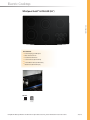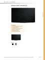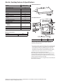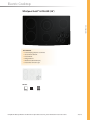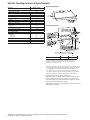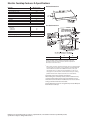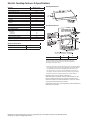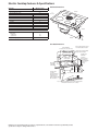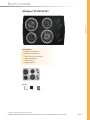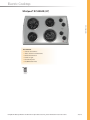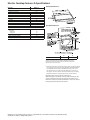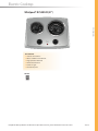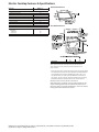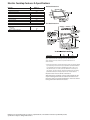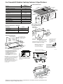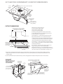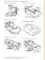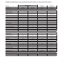
1
Cooktops WHIRlPOOl GOlD® BuIlT-In GAS COOKTOPS At every turn, Whirlpool® gas cooktops offer the power and flexibility to meet a broad range of cooking needs. From the instant, high-heat performance of a 15,000 BTU Power™ burner to the slow, steady cooking of a 550 BTU AccuSimmer® burner, these cooktops are very versatile. A Sealed Burners Sealed burners create an even, stable flame for more efficient cooking. Minimal clean-up required when cooking is complete. E B Full-Width, Cast-Iron Grates COOkiNg B A These durable grates create the flexibility to place pots and pans anywhere on the cooktop. C AccuSimmer® Burner D Preserve the character of delicate foods such as chocolate or sauces. The 550 BTU burner produces a gradual, gentle heat perfect for melting and simmering. C D Formed Glass Styling and Knobs Function and form come together in European-inspired styling that adds a touch of sophistication to the kitchen. E 15,000 BTU Power™ Burner Quickly boils water, sears steaks or stir-fries vegetables with the instant delivery of up to 15,000 BTUs of cooking power. WHIRlPOOl GOlD® BuIlT-In ElECTRIC COOKTOPS Confident cooking starts with technology that adapts to every cooking need. Whirlpool® electric cooktops offer versatile burner configurations like dual, double dual and bridge elements that adjust to the size of pots and pans to increase the cooking surface as needed. A Smooth, Easy-to-Clean Surface Clean-up is easier than ever with a smooth, flat surface that wipes clean without the use of harsh foams or sprays. A B Eco-Friendly Schott Ceran® Cooktop glass ceramic cooktop is manufactured in an environmentally safe process that releases no hazardous metals into the earth. C B F C 6/9" Dual Element Easily adjust the burner size to match the size of pots and pans. Choose the inner ring for slow simmering in large pots and pans or quick boiling in smaller cookware. The outer ring evenly distributes heat through large pots and pans. D E D AccuSimmer® Element Preserve the character of delicate foods such as chocolate or sauces. The low watt element produces gradual, gentle heat perfect for melting and simmering. E Formed Glass Styling Whirlpool gold® electric cooktops feature an attractive contoured shape that matches the design of the Whirlpool gold® suite. F Bridge Element A 700 watt bridge element connects two 1800 watt elements, increasing the total heating area to 4300 watts to accommodate larger pots and pans. Ceran is a Registered Trademark of SCHOTT North America, inc. Electric Cooktop Whirlpool Gold® GJC3655R (36") COOkiNg KEY FEATuRES ■ Formed Styling and graphics ■ glass Touch Controls ■ Double Dual Elements ■ 2-Level Simmer (All Elements) ■ 2-Level Warm Zone (All Elements) ■ Warm-Zone 5th Element (6") COlORS Black(B) Stainless Steel(S) Complete Product Specifications on the back. For all product accessories, please reference the Accessories section. 3Q 2009 Electric Cooktop Features & Specifications Model No. 36" Cooktop Ceramic-Glass Cooktop Surface Units Right Front Left Front Right Rear Left Rear Center Warm Zone 5th Element Infinite-Heat Controls Hot-Surface Indicator Light General Information Total Connected Load (kwh) @ 240 Volts @ 208 Volts Approval Over Single Oven Approval with Downdraft Approx. Shipping Wt. (lbs.) Whirlpool Gold® GJC3655R Yes Radiant 6" 6/9" Dual 7" 6" 5/8" Dual Yes Yes Yes Product Dimensions Cut-Out Dimensions 8.1 6.0 Yes Yes 40 GJC3655R A 35 1⁄2 B 20 1⁄2 36" models require a 30" minimum base cabinet. If cabinet has a drawer, a 4" depth clearance from the countertop to the top of the drawer (or other obstruction) in base cabinet is required. All dimensions are shown in inches. * Note: 24" (61 cm) min. clearance if bottom of wood or metal cabinet is protected by not less than 1⁄4" (0.6 cm) flame retardant millboard covered with not less than No. 28 MSG sheet steel, 0.015" (0.04 cm) stainless steel, or 0.024" (0.06 cm) aluminum or 0.020" (0.05 cm) copper. 30" (76.2 cm) min. clearance between top of cooking platform and bottom of unprotected wood or metal cabinet. Important note on base cabinet construction: After making the countertop cutout, some installations may require notching down the base cabinet side walls to clear the burner box. To avoid this modification, use a base cabinet having side walls wider than the cutout. Cutout dimensions have not changed from previous Whirlpool Gold® Electric Cooktops. Dimensions are for planning purposes only. For complete details, see Installation Instructions packed with product. Specifications subject to change without notice. Electric Cooktop Whirlpool Gold® GJC3654R (36") COOkiNg KEY FEATuRES ■ Formed Styling, graphics and knobs ■ Double Dual Elements ■ AccuSimmer® Element — LF Element ■ Warm-Zone 5th Element (6") ■ Ceramic glass Cooktop ■ Hot Surface indicator Light COlORS Black(B) Stainless Steel(S) Complete Product Specifications on the back. For all product accessories, please reference the Accessories section. 3Q 2009 Electric Cooktop Features & Specifications Model No. 36" Cooktop Ceramic-Glass Cooktop Surface Units Right Front Left Front Right Rear Left Rear Center Warm Zone 5th Element AccuSimmer® System Element Infinite-Heat Controls Hot-Surface Indicator Light Lift-Off Control Knobs General Information Total Connected Load (kwh) @ 240 Volts @ 208 Volts Approval Over Single Oven Approval with Downdraft Approx. Shipping Wt. (lbs.) Whirlpool Gold® GJC3654R Product Dimensions Yes Radiant 6" 6/9" Dual 7" 6" 5/8" Dual Yes Yes Cut-Out Dimensions Yes Yes Yes 8.1 6.0 Yes Yes 40 Optional Accessories Description Griddle Part # 4396096RB GJC3654R A 35 1⁄2 B 20 1⁄2 36" models require a 30" minimum base cabinet. If cabinet has a drawer, a 4" depth clearance from the countertop to the top of the drawer (or other obstruction) in base cabinet is required. All dimensions are shown in inches. * Note: 24" (61 cm) min. clearance if bottom of wood or metal cabinet is protected by not less than 1⁄4" (0.6 cm) flame retardant millboard covered with not less than No. 28 MSG sheet steel, 0.015" (0.04 cm) stainless steel, or 0.024" (0.06 cm) aluminum or 0.020" (0.05 cm) copper. 30" (76.2 cm) min. clearance between top of cooking platform and bottom of unprotected wood or metal cabinet. Important note on base cabinet construction: After making the countertop cutout, some installations may require notching down the base cabinet side walls to clear the burner box. To avoid this modification, use a base cabinet having side walls wider than the cutout. Cutout dimensions have not changed from previous Whirlpool Gold® Electric Cooktops. Dimensions are for planning purposes only. For complete details, see Installation Instructions packed with product. Specifications subject to change without notice. Electric Cooktop Whirlpool Gold® GJC3634R (36") COOkiNg KEY FEATuRES ■ Formed Styling, graphics and knobs ■ AccuSimmer® Element ■ Dual Element ■ Bridge Element ■ Warm-Zone 5th Element (6") ■ Hot Surface indicator Light COlORS Pure White(P) Black(B) Stainless Steel(S) Complete Product Specifications on the back. For all product accessories, please reference the Accessories section. 3Q 2009 Electric Cooktop Features & Specifications Model No. 36" Cooktop Ceramic-Glass Cooktop Surface Units Right Front Left Front Right Rear Left Rear Center Warm Zone 5th Element AccuSimmer® System Element Infinite-Heat Controls Hot-Surface Indicator Light Lift-Off Control Knobs General Information Total Connected Load (kwh) @ 240 Volts @ 208 Volts Approval Over Single Oven Approval with Downdraft Approx. Shipping Wt. (lbs.) Whirlpool Gold® GJC3634R Product Dimensions Yes Radiant 6" 7" Bridge 6" 7" 6/9" Dual Yes Yes Cut-Out Dimensions Yes Yes Yes 8.1 6.0 Yes Yes 40 GJC3634R A 35 1⁄2 B 20 1⁄2 36" models require a 30" minimum base cabinet. If cabinet has a drawer, a 4" depth clearance from the countertop to the top of the drawer (or other obstruction) in base cabinet is required. All dimensions are shown in inches. * Note: 24" (61 cm) min. clearance if bottom of wood or metal cabinet is protected by not less than 1⁄4" (0.6 cm) flame retardant millboard covered with not less than No. 28 MSG sheet steel, 0.015" (0.04 cm) stainless steel, or 0.024" (0.06 cm) aluminum or 0.020" (0.05 cm) copper. 30" (76.2 cm) min. clearance between top of cooking platform and bottom of unprotected wood or metal cabinet. Important note on base cabinet construction: After making the countertop cutout, some installations may require notching down the base cabinet side walls to clear the burner box. To avoid this modification, use a base cabinet having side walls wider than the cutout. Cutout dimensions have not changed from previous Whirlpool Gold® Electric Cooktops. Dimensions are for planning purposes only. For complete details, see Installation Instructions packed with product. Specifications subject to change without notice. Electric Cooktop Whirlpool Gold® GJC3055R (30") COOkiNg KEY FEATuRES ■ Formed Styling and graphics ■ glass Touch Controls ■ Double Dual Elements ■ 2-Level Simmer (All Elements) ■ 2-Level Warm Zone (All Elements) ■ Hot Surface indicator Light Glass Touch Controls COlORS Pure White(P) Black(B) Stainless Steel(S) Complete Product Specifications on the back. For all product accessories, please reference the Accessories section. 3Q 2009 Electric Cooktop Features & Specifications Model No. 30" Cooktop Ceramic-Glass Cooktop Surface Units Right Front Left Front Right Rear Left Rear Infinite-Heat Controls Hot-Surface Indicator Light General Information Total Connected Load (kwh) @ 240 Volts @ 208 Volts Approval Over Single Oven Approval with Downdraft Approx. Shipping Wt. (lbs.) Whirlpool Gold® GJC3055R Product Dimensions Yes Radiant 6" 6/9" Dual 5/8" Dual 7" Yes Yes Cut-Out Dimensions 8.1 6.0 Yes Yes 35 GJC3055R A 29 1⁄2 B 20 1⁄2 30" models require a 30" minimum base cabinet. If cabinet has a drawer, a 4" depth clearance from the countertop to the top of the drawer (or other obstruction) in base cabinet is required. All dimensions are shown in inches. * Note: 24" (61 cm) min. clearance if bottom of wood or metal cabinet is protected by not less than 1⁄4" (0.6 cm) flame retardant millboard covered with not less than No. 28 MSG sheet steel, 0.015" (0.04 cm) stainless steel, or 0.024" (0.06 cm) aluminum or 0.020" (0.05 cm) copper. 30" (76.2 cm) min. clearance between top of cooking platform and bottom of unprotected wood or metal cabinet. Important note on base cabinet construction: After making the countertop cutout, some installations may require notching down the base cabinet side walls to clear the burner box. To avoid this modification, use a base cabinet having side walls wider than the cutout. Cutout dimensions have not changed from previous Whirlpool Gold® Electric Cooktops. Dimensions are for planning purposes only. For complete details, see Installation Instructions packed with product. Specifications subject to change without notice. Electric Cooktop Whirlpool Gold® GJC3054R (30") COOkiNg KEY FEATuRES ■ Formed Styling, graphics and knobs ■ Double Dual Elements ■ AccuSimmer® Element — LF Element ■ Radiant Elements ■ Ceramic glass Cooktop ■ Hot Surface indicator Light Dual elements heated red. COlORS Pure White(P) Black(B) Stainless Steel(S) Complete Product Specifications on the back. For all product accessories, please reference the Accessories section. 3Q 2009 Electric Cooktop Features & Specifications Model No. 30" Cooktop Ceramic-Glass Cooktop Surface Units Right Front Left Front Right Rear Left Rear AccuSimmer® System Element Infinite-Heat Controls Hot-Surface Indicator Light Lift-Off Control Knobs General Information Total Connected Load (kwh) @ 240 Volts @ 208 Volts Approval Over Single Oven Approval with Downdraft Approx. Shipping Wt. (lbs.) Whirlpool Gold® GJC3054R Product Dimensions Yes Radiant 6" 6/9" Dual 5/8" Dual 6" Yes Yes Yes Yes Cut-Out Dimensions 8.1 6.0 Yes Yes 35 Optional Accessories Description Griddle Part # 4396096RB GJC3054R A 29 1⁄2 B 20 1⁄2 30" models require a 30" minimum base cabinet. If cabinet has a drawer, a 4" depth clearance from the countertop to the top of the drawer (or other obstruction) in base cabinet is required. All dimensions are shown in inches. * Note: 24" (61 cm) min. clearance if bottom of wood or metal cabinet is protected by not less than 1⁄4" (0.6 cm) flame retardant millboard covered with not less than No. 28 MSG sheet steel, 0.015" (0.04 cm) stainless steel, or 0.024" (0.06 cm) aluminum or 0.020" (0.05 cm) copper. 30" (76.2 cm) min. clearance between top of cooking platform and bottom of unprotected wood or metal cabinet. Important note on base cabinet construction: After making the countertop cutout, some installations may require notching down the base cabinet side walls to clear the burner box. To avoid this modification, use a base cabinet having side walls wider than the cutout. Cutout dimensions have not changed from previous Whirlpool Gold® Electric Cooktops. Dimensions are for planning purposes only. For complete details, see Installation Instructions packed with product. Specifications subject to change without notice. Electric Cooktop Whirlpool Gold® GJD3044R (30") COOkiNg KEY FEATuRES ■ Formed Styling, graphics and knobs ■ Built-in Downdraft Ventilation System with 350 CFM Output ■ Removable Filter ■ Vent Cover ■ Ceramic glass Cooktop ■ Hot Surface indicator Light COlORS Black(B) Complete Product Specifications on the back. For all product accessories, please reference the Accessories section. 3Q 2009 Electric Cooktop Features & Specifications Model No. 30" Cooktop Ceramic-Glass Cooktop Surface Units Right Front Left Front Right Rear Left Rear Downdraft Vent System Infinite-Heat Controls Hot-Surface Indicator Light Lift-Off Control Knobs General Information Total Connected Load (kwh) @ 240 Volts @ 208 Volts Approx. Shipping Wt. (lbs.) Whirlpool Gold® GJD3044R Yes Radiant 6" 6/9" Dual 5/8" Dual 6" Yes Yes Yes Yes Product Dimensions 31 1/2" 21 13⁄16" 2 15/16" 7.2 5.4 57 15 5/8" 3" Cut-Out Dimensions Cutout Width 30" (76.2 cm) – 30" (76.2 cm) Combustible area above countertop 21" (53.3 cm) cutout depth 2" min. (5.1 cm) Do not seal cooktop to countertop Junction box, or outlet – 12" (30.5 cm) min. from bottom of countertop. 10" (25.4 cm) from right side of cabinet Select required duct cutout for exhaust duct location 13" (33 cm) recommended upper cabinet depth 18" (45.7 cm) minimum clearance upper cabinet to countertop within minimum clearance to cooktop 29 1/2" (74.9 cm) – 30" (76.2 cm) 1" (2.5 cm) min. distance to nearest left and right side combustible surface above cooktop Dimensions are for planning purposes only. For complete details, see Installation Instructions packed with product. Specifications subject to change without notice. Electric Cooktop Whirlpool Gold® GJC3034R (30") COOkiNg KEY FEATuRES ■ Formed Styling, graphics and knobs ■ AccuSimmer® Element ■ Dual Element ■ Bridge Element ■ Ceramic glass Cooktop ■ Hot Surface indicator Light Bridge Element COlORS Pure White(P) Pure Biscuit(C) Black(B) Stainless Steel(S) Complete Product Specifications on the back. For all product accessories, please reference the Accessories section. 3Q 2009 Electric Cooktop Features & Specifications Model No. 30" Cooktop Ceramic-Glass Cooktop Surface Units Right Front Left Front Right Rear Left Rear AccuSimmer® System Element Infinite-Heat Controls Hot-Surface Indicator Light Lift-Off Control Knobs General Information Total Connected Load (kwh) @ 240 Volts @ 208 Volts Approval Over Single Oven Approval with Downdraft Approx. Shipping Wt. (lbs.) Whirlpool Gold® GJC3034R Product Dimensions Yes Radiant 6" 7" Bridge 6/9" Dual 7" Yes Yes Yes Yes Cut-Out Dimensions 8.1 6.0 Yes Yes 35 GJC3034R A 29 1⁄2 B 20 1⁄2 30" models require a 30" minimum base cabinet. If cabinet has a drawer, a 4" depth clearance from the countertop to the top of the drawer (or other obstruction) in base cabinet is required. All dimensions are shown in inches. * Note: 24" (61 cm) min. clearance if bottom of wood or metal cabinet is protected by not less than 1⁄4" (0.6 cm) flame retardant millboard covered with not less than No. 28 MSG sheet steel, 0.015" (0.04 cm) stainless steel, or 0.024" (0.06 cm) aluminum or 0.020" (0.05 cm) copper. 30" (76.2 cm) min. clearance between top of cooking platform and bottom of unprotected wood or metal cabinet. Important note on base cabinet construction: After making the countertop cutout, some installations may require notching down the base cabinet side walls to clear the burner box. To avoid this modification, use a base cabinet having side walls wider than the cutout. Cutout dimensions have not changed from previous Whirlpool Gold® Electric Cooktops. Dimensions are for planning purposes only. For complete details, see Installation Instructions packed with product. Specifications subject to change without notice. Electric Cooktop Whirlpool® RCC3024R (30") COOkiNg KEY FEATuRES ■ Ceramic-glass Surface ■ Two 6", One 7" and One 9" Elements ■ Radiant Elements ■ infinite-Heat Controls ■ Lift-Off Control knobs ■ Hot Surface indicator Light COlORS White(Q) Biscuit(T) Black(B) Complete Product Specifications on the back. For all product accessories, please reference the Accessories section. 3Q 2009 Electric Cooktop Features & Specifications Model No. 30" Cooktop Ceramic-Glass Cooktop Surface Units Right Front Left Front Right Rear Left Rear Infinite-Heat Controls Hot-Surface Indicator Light Lift-Off Control Knobs General Information Total Connected Load (kwh) @ 240 Volts @ 208 Volts Approval Over Single Oven Approval with Downdraft Approx. Shipping Wt. (lbs.) Whirlpool® RCC3024R Yes Radiant 6" 9" 7" 6" Yes Yes Yes Product Dimensions Cut-Out Dimensions 6.7 5.0 Yes Yes 35 RCC3024R A 29 1⁄2 B 20 1⁄2 30" models require a 30" minimum base cabinet. If cabinet has a drawer, a 4" depth clearance from the countertop to the top of the drawer (or other obstruction) in base cabinet is required. All dimensions are shown in inches. * Note: 24" (61 cm) min. clearance if bottom of wood or metal cabinet is protected by not less than 1⁄4" (0.6 cm) flame retardant millboard covered with not less than No. 28 MSG sheet steel, 0.015" (0.04 cm) stainless steel, or 0.024" (0.06 cm) aluminum or 0.020" (0.05 cm) copper. 30" (76.2 cm) min. clearance between top of cooking platform and bottom of unprotected wood or metal cabinet. Important note on base cabinet construction: After making the countertop cutout, some installations may require notching down the base cabinet side walls to clear the burner box. To avoid this modification, use a base cabinet having side walls wider than the cutout. Dimensions are for planning purposes only. For complete details, see Installation Instructions packed with product. Specifications subject to change without notice. Electric Cooktop Whirlpool® RCS3014R (30") COOkiNg KEY FEATuRES ■ High-Speed Coil Elements ■ Porcelain-on-Steel* Surface ■ Two 6" and Two 8" Coil Elements ■ infinite-Heat Controls ■ Power on Light ■ Chrome Drip Pans COlORS White(Q) Black(B) Stainless Steel(S)* * Stainless model features stainless steel cooktop. Complete Product Specifications on the back. For all product accessories, please reference the Accessories section. 3Q 2009 Electric Cooktop Features & Specifications Model No. 30" Cooktop Porcelain-on-Steel Cooktop Surface Units Right Front Left Front Right Rear Left Rear Infinite-Heat Controls Power-On Light Chrome Drip Pans Lift-Off Control Knobs General Information Total Connected Load (kwh) @ 240 Volts @ 208 Volts Approval Over Single Oven Approval with Downdraft Approx. Shipping Wt. (lbs.) Whirlpool® RCS3014R Product Dimensions Yes** Hi-Speed Coil 8" 6" 6" 8" Yes Yes Yes Yes Cut-Out Dimensions 7.2 5.4 Yes Yes 35 ** Stainless model features stainless steel cooktop. RCS3014R A 28 7⁄8 B 18 5⁄8 30" models require a 30" minimum base cabinet. If cabinet has a drawer, a 4" depth clearance from the countertop to the top of the drawer (or other obstruction) in base cabinet is required. All dimensions are shown in inches. * Note: 24" (61 cm) min. clearance if bottom of wood or metal cabinet is protected by not less than 1⁄4" (0.6 cm) flame retardant millboard covered with not less than No. 28 MSG sheet steel, 0.015" (0.04 cm) stainless steel, or 0.024" (0.06 cm) aluminum or 0.020" (0.05 cm) copper. 30" (76.2 cm) min. clearance between top of cooking platform and bottom of unprotected wood or metal cabinet. Important note on base cabinet construction: After making the countertop cutout, some installations may require notching down the base cabinet side walls to clear the burner box. To avoid this modification, use a base cabinet having side walls wider than the cutout. Dimensions are for planning purposes only. For complete details, see Installation Instructions packed with product. Specifications subject to change without notice. Electric Cooktop Whirlpool® RCS3004R (30") COOkiNg KEY FEATuRES ■ Stainless Steel Surface ■ Two 6" and Two 8" Coil Elements ■ infinite-Heat Controls ■ Power on Light ■ Chrome Drip Pans ■ Lift-Off Control knobs COlORS Stainless Steel(S) Complete Product Specifications on the back. For all product accessories, please reference the Accessories section. 3Q 2009 Electric Cooktop Features & Specifications Model No. 30" Cooktop Stainless Steel Surface Surface Units Right Front Left Front Right Rear Left Rear Infinite-Heat Controls Power-On Light Chrome Drip Pans Lift-Off Control Knobs General Information Total Connected Load (kwh) @ 240 Volts @ 208 Volts Approval Over Single Oven Approval with Downdraft Approx. Shipping Wt. (lbs.) Whirlpool® RCS3004R Yes Coil 8" 6" 6" 8" Yes Yes Yes Yes Product Dimensions Cut-Out Dimensions 6.7 5.0 Yes Yes 35 RCS3004R A 28 7⁄8 B 18 5⁄8 30" models require a 30" minimum base cabinet. If cabinet has a drawer, a 4" depth clearance from the countertop to the top of the drawer (or other obstruction) in base cabinet is required. All dimensions are shown in inches. * Note: 24" (61 cm) min. clearance if bottom of wood or metal cabinet is protected by not less than 1⁄4" (0.6 cm) flame retardant millboard covered with not less than No. 28 MSG sheet steel, 0.015" (0.04 cm) stainless steel, or 0.024" (0.06 cm) aluminum or 0.020" (0.05 cm) copper. 30" (76.2 cm) min. clearance between top of cooking platform and bottom of unprotected wood or metal cabinet. Important note on base cabinet construction: After making the countertop cutout, some installations may require notching down the base cabinet side walls to clear the burner box. To avoid this modification, use a base cabinet having side walls wider than the cutout. Dimensions are for planning purposes only. For complete details, see Installation Instructions packed with product. Specifications subject to change without notice. Electric Cooktop Whirlpool® RCS2012R (21") COOkiNg KEY FEATuRES ■ Stainless Steel Surface ■ One 6" and One 8" Coil Element ■ High Speed Coil Elements ■ infinite-Heat Controls ■ Power on Light ■ Chrome Drip Pans COlORS Stainless Steel(S) Complete Product Specifications on the back. For all product accessories, please reference the Accessories section. 3Q 2009 Electric Cooktop Features & Specifications Model No. 21" Cooktop Stainless Steel Surface Surface Units Right Front Left Front Infinite-Heat Controls Power-On Light Chrome Drip Pans Lift-Off Control Knobs General Information Total Connected Load (kwh) @ 240 Volts @ 208 Volts Approx. Shipping Wt. (lbs.) Whirlpool® RCS2012R —2-Element Yes High Speed Coil 8" 6" Yes Yes Yes Yes Product Dimensions Cut-Out Dimensions 3.4 2.5 18 RCS2012R A 18 5⁄8 B 15 1⁄2 21" models require 24" base cabinet. If cabinet has a drawer, a 4" depth clearance from the countertop to the top of the drawer (or other obstruction) in base cabinet is required. All dimensions are shown in inches. * Note: 24" (61 cm) min. clearance if bottom of wood or metal cabinet is protected by not less than 1⁄4" (0.6 cm) flame retardant millboard covered with not less than No. 28 MSG sheet steel, 0.015" (0.04 cm) stainless steel, or 0.024" (0.06 cm) aluminum or 0.020" (0.05 cm) copper. 30" (76.2 cm) min. clearance between top of cooking platform and bottom of unprotected wood or metal cabinet. Important note on base cabinet construction: After making the countertop cutout, some installations may require notching down the base cabinet side walls to clear the burner box. To avoid this modification, use a base cabinet having side walls wider than the cutout. Dimensions are for planning purposes only. For complete details, see Installation Instructions packed with product. Specifications subject to change without notice. Electric Cooktop Whirlpool® RCS2002R (21") COOkiNg KEY FEATuRES ■ Stainless Steel Surface ■ One 6" and One 8" Coil Element ■ infinite-Heat Controls ■ Power on Light ■ Chrome Drip Pans ■ Lift-Off Control knobs COlORS Stainless Steel(S) Complete Product Specifications on the back. For all product accessories, please reference the Accessories section. 3Q 2009 Electric Cooktop Features & Specifications Model No. 21" Cooktop Stainless Steel Surface Surface Units Right Front Left Front Infinite-Heat Controls Power-On Light Chrome Drip Pans Lift-Off Control Knobs General Information Total Connected Load (kwh) @ 120 Volts Approx. Shipping Wt. (lbs.) Whirlpool® RCS2002R —2-Element Yes Coil 8" 6" Yes Yes Yes Yes Product Dimensions Cut-Out Dimensions 2.4 18 RCS2002R A 18 5⁄8 B 15 1⁄2 21" models require 24" base cabinet. If cabinet has a drawer, a 4" depth clearance from the countertop to the top of the drawer (or other obstruction) in base cabinet is required. All dimensions are shown in inches. * Note: 24" (61 cm) min. clearance if bottom of wood or metal cabinet is protected by not less than 1⁄4" (0.6 cm) flame retardant millboard covered with not less than No. 28 MSG sheet steel, 0.015" (0.04 cm) stainless steel, or 0.024" (0.06 cm) aluminum or 0.020" (0.05 cm) copper. 30" (76.2 cm) min. clearance between top of cooking platform and bottom of unprotected wood or metal cabinet. Important note on base cabinet construction: After making the countertop cutout, some installations may require notching down the base cabinet side walls to clear the burner box. To avoid this modification, use a base cabinet having side walls wider than the cutout. Dimensions are for planning purposes only. For complete details, see Installation Instructions packed with product. Specifications subject to change without notice. Modular Downdraft Cooktop Whirlpool® SC8720ED (30" Gas) COOkiNg KEY FEATuRES ■ Porcelain-on-Steel Surface ■ Two 10,000 BTU Open Burners (Right Bay) ■ Left Bay Open for Optional Module ■ Downdraft Ventilation System ■ Pilot Light ignition ■ Lift-Off Control knobs OPTIOnAl GAS COOKTOP MODulES Two 10,000 BTu SurfaceBurner Module Black: SCM10DB Porcelain-on-Steel Spillguard™ Surface non-Stick Griddle Module SCM40DB (grill Module SCM20DB Required as Power Source) non-Stick Grill Module Black: SCM20DB Grill Cover Black: SCM50DB COlORS Black(B) Complete Product Specifications on the back. For all product accessories, please reference the Accessories section. 3Q 2009 T MODEL NUMBERS ... D OVERALL DIMENSIONS room, but external to the range. Electrical: A 120-volt, 60-Hz, AC-only, 15- or 20Cutout dimensions Gas Downdraft Cooktop Gas Downdraft Modular 30" Cooktop Features &electrical Specifications ampere, fused supply is required. A time® Cabinet 29-7/8" (75.9 cm) drawers under the cooktop will need to be width 15-5/8" (39.7 cm) blower housing depth 3-5/16" (8.4 cm) burner box depth delay fuse or circuit21-1/2" breaker recommended. It is (54.6 is cm) depth recommended that a separate circuit serving only PRODUCT MODEL NUMBERSremoved and the drawer OVERALL DIMENSIONS ly: Use 3/4" rigid pipe gas supply line Product Whirlpool® fronts installed this applianceDimensions be provided. location. size pipe on long for correct A smallerModel No. Modular 20-15/16"Downdraft permanently on front of SC8720ED sult in insufficient gas supply. With CABINET OPENING DIMENSION (53.2 cm) Venting system: Use metal vent only. cabinet. cutout depth 30" SC8720ED ktop. ing or tubing size can be 1/2" (75.9 cm) slab, PVC may be Exception: Under29-7/8" a concrete 21-1/2" (54.6 cm) width ecified on the permit, it Cooktop depth local codes is used; see Installation Instructions for details. Rigid Gas supply: Use 3/4" rigid pipe gas supply line 15/16" (2.4 cm) 30" (76.2 cm) minimum when ed that new flexible metal tubing, Porcelain-on-Steel Cooktop Yes to the range location. A smaller size1-7/8" pipe(4.8oncm) long metal vent is recommended. Do not use plastic or ight side of the minimum higher than 18" (45.7 cm) fied by AGA or CSA, 4-5 distance tofeet long, runs may result in insufficient gasminimum supply.space With pressure metal foil vent. Burner Type Open or edge of regulator can size be can to nchdraft I.D.,areas, be usedbacksplash for connecting the L.P. gas, piping Blower or tubing befront 1/2" ng vertical wall countertop Ignition Pilot-Light This downdraft cooktop is rated at 60 feet swiveled 90°. g rigid vents gas or fans. minimum. If local codes permit, it is 13" (33 cm) supply line. A 1/2" male pipe (18.3 m) of straight vent or the equivalent. n. maximum upper Burner BTU/hr. Rating:recommended that new flexible metal tubing, wiring box eded for connection to pressure cabinet depth See Note** ® “Electrical cover Right Front 10,000 Minimum base cabinet dimensions — If vent length is 10 feet (3 m) or less, 5" design-certified by AGA or CSA, 4-5 feet long, pressurefor minimum male pipe threads. An individual grease 30" Cooktop regulatorclearances. 30"used (76.2for cm) base Open cabinet. Blower can be 1/2- or 3/4-inch I.D., be connecting theBayGas Downdraft diameter round vent may be used. If vent length is Left off valve in Front the same container lable. See must be located swiveled 90°. 24" (61.0 cm)Abase cabinet depth range to the rigid gas supply line. 1/2" male pipe 3-5/16" more than 10 feet (3 m), use 6" diameter round or xternal to the range. Rightduct Rear 25" 15-5/8" (63.5 cm) countertop 11-7/8" Select required (8.410,000 cm) depth wiring box thread is needed for connection (39.7 cm)to pressure (30.2 cm) cm) rectangular vent. 3-1/4" x 10" (8.3 x 25.4 cutout (see page 4 burner box Countertop must be cover blower Left Rear Open Bay for exhaust duct PRODUCT MODEL NUMBERS OVERALL DIMENSIONS regulator female pipe threads. An individual supported within : A 120-volt, AC-only, 15or 20depth ktop is to be 60-Hz,cutout housing grease location). Venting system must terminate to the outside. 3" (7.6 cm) of cutout. Cutout preparation: manual shutoff valve must be located in theYes same container depth Vent System ed electrical supply is Downdraft required. A time14" 3-5/16" 15-5/8" Decorative room,SC8720ED but external to the range. laminate —Yes 11-7/8" r circuit breaker is recommended. It is (35.6 cm) Non-Turn Grates All openings incm) the wall(8.4orcm) floor where cooktop is (39.7 (30.2 cm) Chamfer all exposed burner box blower 0" (0 cm) ed that a separate circuit serving only 29-7/8" (75.9 cm) on in to be installed must be depth sealed. Electrical: A 120-volt, 60-Hz, AC-only, 15or laminate. 20Lift-Off Control Knobs Yes edges to prevent chipping 21-1/2" (54.6 cm) housing width 11" (27.9 cm) depth depth dce be provided.16" (40.6General Cut radius corners andgas to insure fused electrical supply required. Afile timeGas supply: Use 3/4"isrigid pipe supply line Information ampere, cm) 14" Do Not seal smooth edges and to prevent cracking. CABINET OPENING DIMENSIONS may Use metal vent only. delaytofuse circuit breaker is It ison long (35.6 cm) wall location. ystem: Minimum distance theorside range A recommended. smaller size 61 pipe cooktop to Approx. Shipping Weight (lbs.) combustible vertic 4" (10.2 recommended a separate circuit serving only With countertop. mage, nder a concrete slab, PVCcm) may be runs maythat result in insufficient gas supply. 18" (45.7 cm) abov 4" (10.2 cm) this appliance provided. stallation Instructions for details. Rigid L.P. gas, be piping or tubing size can be 1/2" Side clearance — 2" (5.1 cm) Installation location Note: 30" (76.2 cm) minimum when bottom of woo CABINET OPENING DIMENSIONS 30" (76.2 cm) minimum when ** Venting system: Use metal vent only. s recommended. Do not use plastic or minimum clearance is required. 6" minimum. If localhigher codesthan permit, it is should provide sufficient by not less than 1/4" flame retardant millboard cov 18" (45.7 cm) oline, or room for: Exception: Under a concrete slab, PVC may be tubing, (15.2 cm) clearance between side Optional Accessories—Modules Cut-Out Dimensions nt. recommended that new flexible metal MSG sheet steel, 0.015" stainless steel, 0.024" alum • Removing grease and of cooktop and side wall is used;design-certified see Installation Instructions for details. Rigid Side clearance — 2"clearance (5.1 cm) between the top containers. by (40.6 AGAcm) or CSA, 4-5 feet long, rear 16" Installation location 36" (91.4 cm) minimum pressure aft is rated at 60 feet Install hiscooktop or 30" (76.2 cm) minimum when recommended for maximum Exhaust Duct • Accessing gas regulator. metal vent is recommended. Do not use plastic or minimum clearance is regulator required. 6" wall 13" for (33 should provide sufficient bottom Description Part No.cm) Blower of unprotected wood or sheet metal. higher than can 18" be (45.7 cm) 1/2- or 3/4-inch I.D., be used connecting the grounded straight vent or the equivalent. room for: maximum upper ventilation performance. electrical Cutout Locations (15.2 cm) clearance between side metal foil vent. swiveled 90°. • Removing grease cabinet range to the See rigidNote** gasSCM10DB — Black supply line. depth A 1/2" male pipeoutlet Two-Burner 28-7/8" of cooktop and side wall is hELL is 10GAS feet (3 m) or less, 5" Rear(73.3 clearance — The rear containers. edge within for minimum This cabinet downdraft cooktop iscabinet rated at 60 feet bottom cm) box thread is needed for connection to pressure maximum • Accessing gas regulator. recommended forwiring shaded area (33 cm) Grillis clearances. of 13" the cooktop may be installed cover und vent may be used.Non-Stick If vent length cutout width bottom (18.3 regulator m) of straight ventpipe or SCM20DB — Black the equivalent. of rear wall. 20-15/16" maximum upper ventilation performance. 18" (45.7 cm) female threads. An individual flush with countertop backsplash. cabinet depth Note** grease (53.2 cm) Cabinet drawers Non-Stick Griddle 0 feet (3 m), use 6" diameter round or (requires minimumSee clearance under the rear edge Observe governing codes If vent length is 10Important: feetvalve (3 m) or less, Rear clearance — The SCM40DB — Black Install gas line within shaded for minimum 15/16" manual shutoff must beall5" located in11"the same container (2.4 cm) cutout depth cooktop 28-7/8" (73.3 cm) clearance upper cabinet 14"SCM20DB (35.6 cm) as aofpower (27.9 cm) needmay to bebe installed andmay ordinances. area cabinet. source) " (8.3 x 25.4 cm) rectangular vent. clearances. cutoutrear width of thewill cooktop trical to countertop diameter round be the used. If vent length is between edge 3-5/16" of appliance 18" (45.7 cm) 15-5/8" room, but vent external to range. removed and the drawer 11-7/8" Gas Line Location Proper installation is your28-7/8" responsibility. (73.3 cm) (8.4 cm) flush with countertop backsplash. Cover SCM50DB — Black cm) is recommended. more than 10 feet• Make (3 m),sure use 6" diameter round or and (39.7 rear wall (30.2 cm) yem phone must terminate toGrill the outside. minimum clearance fronts installed burner box you have everything necessary for correct blower 15/16" (2.4oncm) clearance 15/16" (2.4 cm) upper cabinet 20-15/16" permanently front of11" (27.9 cm) Electrical: A 120-volt, 60-Hz, AC-only, depth — 3-1/4" x 10" (8.3 xinstallation. 25.4 cm) rectangular vent. 15- or 20housing clearance Motor/blower to countertop (53.2 cm) minimum between rear edge of appliance cabinet. depth in the wall or floor where cooktop is ampere, electrical is required. A timedistance to • Have a qualifiedsupply install this cooktop. 2" (5.1depth cm) clearance is required1-7/8"cutout as (4.8 and rear wall is recommended. Venting systemfused must terminate totechnician the outside. 14"cm) 0" (0 cm) • Comply with the installation clearances specified on 2" backsplash minimum ed must be sealed. Clearance Dimensions between motordrawers and cabinet for delay fuse or circuit breaker is recommended. It is (5.1the (35.6space cm) or’s Cabinet under the Important: Observe all governing codes Motor/blower clearance — cm) or vertical to front edge of model/serial rating plate. 28-7/8" (73.3 cm) proper cooktop cooling. will need to be 4" (10.2 cm) All openings in the wall or afloor where circuit cooktopserving is cutoutonly and ordinances. recommended that separate wall15/16" (2.4 cm) 2" (5.1 cm) clearance is required width supplier’s countertop Installation location should Model/serial rating plate is located on the right side of the Do Not seal 0" (0 cm) minimum 30" (76.2 cm) minimum when 1-7/8" (4.8 cm) removed and the drawer 6" (15.2 cm) clearance is 2" to becm) installed must be sealed. Proper installation is your responsibility. between motor and cabinet for sufficientMinimum room for: distance to nearest this appliance beprovide provided. distance to minimum space downdraft plenum. to higher than 18" (45.7cooktop (5.1 cm) fronts installed • Removing grease containers. recommended for maximum backsplash or proper • Make sure you have everythingcountertop. necessary for correct combustible vertical surface extending to front edge of cooling. Cooktop location should away from strong draft areas, permanently on front of • Accessing regulator. CABINET OPENING DIMENSIONS wall 20-15/16" r gas countertop Venting system: Usegas metal vent only. 18" be (45.7 cm) above cooktop Do Not seal vertical installation. 6" (15.2 cm) clearance is (53.2 performance. cm) such as windows, doors and strong heating vents cooktop or fans. to cabinet. Minimum distance to nearest cutout depth Cabinet drawers under Select required • Have a qualified technician install this cooktop. Important: Observe all governing codes recommended for the maximum Exception: Under a concrete slab, PVC may be 13" (33 cm) combustible vertical surface extending Locate cooktop for convenient use in kitchen. countertop. Note: 30" (76.2 cm) minimum when bottom of wood or metal cabinet is protected 28-7/8" (73.3 cm) 16" (40.6 cm) **used; Countertop must be supported vent cutout cooktop will need to be maximum upper specified andGrounded ordinances. 18" (45.7 cm) above cooktop performance. • Comply with the installation clearances on1/4" the flame cutout width outletmillboard isfor required. SeeRigid “Electrical electrical see Instructions details. by not lessInstallation than retardant covered with not less than No. 28 base cabinetand dimensions — cabinet depth See Note** Side clearance — 2" (5.1 c within 3" (7.6 cm) of cutout. MinimumInstallation removed the drawer model/serial rating plate. Proper installation is your responsibility. location 2" requirements,” Page 2. for minimum 30" (76.2 cm) minimum 30" when bottom wood or metal is protected (76.2 cm) of minimum when cabinet 30" MSG sheet is steel, 0.015" stainless steel, 0.024" or 0.020" copper. 15/16" (2.4 cm) installed (76.2 should cm) fronts base cabinet. metal recommended. Do not usealuminum plastic or minimum clearance is require ** Note: provide sufficient (5.1 cm)higher Model/serial rating plate is located on thevent right side of the • Make sure you have everything necessary for correct must be clearances. minimum than (45.7 cm) 1-7/8"millboard (4.8 cm)18" Proper gas supply connection must be available. See by not less than 1/4" flame retardant with less 24" than No. 28 20-15/16" front of(15.2 cm) clearance between (61.0 cm) permanently base depth room for:2"cabinet on min. If cabinet has drawers, drawers willcovered need to benot removed distance to 18"clearance (45.7 cm) between minimum space 36" (91.4 minimum the3.top of the cookingMSG platform and metal foil cm) vent. downdraft plenum. installation. (53.2 cm) “Gas supply requirements,” Page sheet steel, 0.015" stainless steel, 0.024" aluminum or 0.020" copper. installer, uct cabinet. • Removing grease 25" (63.5 cm) countertop depth motor backsplash or and drawer fronts installed on front of cabinet. to front edge of minimum clearance Select required duct (5.1 cm) cutout depth of cooktop and side wall is of unprotected wood orterminate sheet metal. bottom Cooktop location should be away from strong draft • Have aareas, qualified technician this cooktop. vertical wall install countertop upper cabinet Venting duct must outdoors. containers. blower cutout (see page 4 min. ations Countertop must This downdraft cooktop is rated at 60 feet supplier. 36" (91.4 cm) minimum clearance between the top of thebe cooking platform and 25-7/8" such as windows, doors and strong heating or fans. countertop for exhaustclearance duct • Accessing • Comply withtothe thebe Exhaust Ductvents motorgas regulator. recommended for maximum 13" (33 cm) supported within All openings in installation the wall or clearances floor wherespecified cooktopon is to cabi 28-7/8" (65.7 cm) bottom of unprotected wood or sheet metal. cutout location). Locate cooktop for convenient use in kitchen. (18.3 m) of straight vent or the equivalent. 3" (7.6maximum cm) of cutout. model/serial rating blower upper ventilation performance. Cutout Locations installed must beplate. sealed. Cutout preparation: (73.3 cm) 25-7/8" 15/16" (2.4 cm) clearance cabinet depth See base Note** Grounded electrical outlet is required. See “Electrical 28-7/8" Minimum cabinet dimensions — — Decorative1-7/8" Model/serial rating plate is located on the right side of the (65.7 cm) cutout width minimum Minimum (4.8 cm)— base cabinet dimensions laminate 20-15/16" If vent length is 10 feet (3 m) or less, 5" Rear clearance — The rear 2" for minimum requirements,” Page 2. (73.3plenum. cm) distance to 30" (76.2 space downdraft cm) base cabinet. (5.1 cm) Chamferminimum allfront exposed (53.2 cm) clearances. backsplash or gas may line within sha cooktop be installe to edge ofbase cabinet dimensions cutout width 30" (76.2 cm) base cabinet diameter round vent may beIfused. Iffrom ventstrong length isinareas, Minimum — connection must be available. See 20-15/16" 0" (0Proper cm) gas supplycutout WARNING: the information 14" (35.6 cm) of theInstall Cooktop location should be away draft depth vertical wall 24" (61.0 cm) base cabinet depth edges to prevent chipping countertop 18" (45.7 cm) laminate. flusharea cabinet. backspl withofcountertop 24" (61.0 (53.2 cm) 11"cm) (27.9base cm) cabinet depth “Gas supply requirements,” Pagemore 3. such as windows, doors and strong heating vents or fans. 30" (76.2 cm)file base cabinet 25" (63.5 cm) countertop depth than 10 this feet (3 m),Select userequired 6"not diameter rounddepth or manual is followed minimum clearance Cut radius corners and to insure duct cutout Line Location 16" (40.6 cm)25" (63.5 cm) countertop depth 15/16" duct must terminate outdoors. LocateGas cooktop for convenient (see page 4in kitchen. Countertop must be cabinet 24" upper (61.0 cm) base cabinet depth(2.4 cm) clearance Do Not Venting seal smooth edges and to prevent cracking. 3-1/4" xtoGrounded 10" (8.3 x 25.4 cm) rectangular vent.may exactly, acutout fire or use explosion BecauseGas Whirlpool Dimensions are for planning purpos side wall commitment to improve for exhaust duct distance nearest to countertop supported within cooktopAll to openings in the wall or Minimum between LineCorporation Locationpolicy includes a continuous floor where cooktop is to beelectrical outlet is required. See “Electrical 25"cabinet (63.5 cm) countertop depth rear edge of applian ) base dimensions —Instructions cutout vertical surface extending 4" (10.2 cm) our products, we reserve the right to change materials andMinimum specifications without notice. packed with product. S 3" (7.6 cm) of cutout. result causing property damage, countertop. 11"Page (27.92. cm) location). installed must be sealed. combustible requirements,” Cutout preparation: and rear wall is recommended Venting system must terminate to the outside. 15/16" 18" (45.7(2.4 cm) cm) above cooktop 30" (76.2 cm) base cabinet. 4" (10.2 cm) 11" (27.9 cm) injury or death. Properpersonal gas supply connection must be available. See minimum Decorative laminate — Location 1-7/8" (4.8 cm) 24" (61.0 cm) base cabinet depth Electrical Outlet Motor/blower clearance — distance to “Gas supply requirements,” Page 3. minimum space All openings in the wall or floor where1-7/8" all exposed (4.8 cm) 25" (63.5 cm) countertop depth cooktop isside wall Select requiredChamfer Electrical Outlet Location duct (76.2 cm) minimum when bottom of wood ** Note: 30"WARNING: 2" (5.1 cm) clearance is requ backsplash If by the information incm) 4" (10.2 cm) to front edge of — duct Domust NOT storeoutdoors. or 11" use gasoline, minimum space or edges chipping must laminate. Venting terminate cutout (see page 4 to preventCountertop or metal cabinet is protected not less than 1/4" 4" (10.2 be side wall 0" (0 cm) (27.9 cm) or vertical 2" to be installed must be sealed. 4" (10.2 cm) to front edge of countertop between motor and cabinet fo for cm) exhaust duct this manual is not flame retardant millboard covered withfollowed not less than All openings Cut radius corners and filewithin to insure supported 4" (10.2 other vapors and in 16" theflammable wallcm) or floor where cooktop is to be wall (5.1 cm) (40.6 cutout location). countertop No. 28 MSG sheet steel, 0.015" stainless steel, 3" (7.6 cm) of cutout. proper smooth edges and to prevent cracking. rearCutout 16" (40.6 cm) installed must be sealed. preparation: exactly, a fire or explosion may Install cooling. liquids in the vicinity of this or side wall 0.024" aluminum or 0.020" copper. ntact a wall Do Not seal 2" 6"grounded (15.2 cm) clearance is Decorative 4" (10.2 cm) causing property Minimum distance to nearestlaminate — re that the 36" (91.4result cm) minimum clearance between the damage, top electrical cooktop to (5.1any cm) other appliance. recommended for maximum allextending exposed 4" (10.2 cm)Chamfer outlet of the cooking platforminjury and bottom ofdeath. unprotected combustible vertical surface min. countertop. make ed sure personal orSelect WARNING: If the information in within wood or sheet metal. required 18" (45.7bottom cm)Install above cooktop edges to prevent chipping laminate. performance. cabinet —motor WHAT TO DO IF YOU SMELL16" GAS 16" (40.6 cm) 16" (40.6 cm) 11" (27.9 cm) Countertop must be supported ational cabinet shaded area 25-7/8" (40.6 cm) 16" (40.6 cm) and file to insure Countertop must be supported blower vent cutout Install this manual is not followed Cut radius corners bottom cutout. of rear wall. (65.7 cm) Do NOT tryoftocutout. light any t edition*, within 3" (7.6 cm) — ofDo NOT store or use gasoline, clearance or•within 16" (40.6 cm) ofgrounded wood or metal cabinet (7.6 cm) grounded smooth edges and is to protected prevent cracking. ** Note: 30" (76.2 cm) minimum when bottom rear electrical a3"fire or explosion may side wall rear Side clearance — 2"flammable (5.1 cm) minimum clearance electrical appliance. by not less thanInstall 1/4" gas flame millboard covered with not less than No. 28 other vapors andexactly, lineretardant within shaded Motor/blower clearance — 2" (5.1 cm) wall outlet 14" (35.6 cm) wall 11" (27.9 cm) 4" (10.2 cm) 2" outlet s drawers, drawers will need to be removed is required. 6" (15.2 cm) clearance between side result causing property damage, area of cabinet. 16" (40.6 cm) If cabinet of has this drawers, to be removed rear sheet steel, 0.015" stainless steel, 0.024"within MSG aluminum or 0.020" copper. Install clearance isneed required between motor and • Do will NOT touch any electrical nto a wall. liquids in the vicinity or drawers within ronts installed on front of cabinet. (10.2cm) cm) wall of cooktop and side wall is recommended for installed and drawer fronts on front of cabinet. 28-7/8" (73.3 cm)4"(5.1 groundedarea cabinet cabinet personal injury or death. shaded cabinet for proper cooling. 6" (15.2 cm) shaded area covering min. switch; Do NOT use any phone any other appliance. electrical 36" (91.4 cm) minimum clearance between the top of the cooking platform and maximum ventilation performance. bottom of rear wall. bottom of rear wall. Exhaust Duct clearance is recommendedcabinet for maximum motor outlet you touch bottom bottom in your building. unprotected wood orcabinet sheet metal. within Rear clearance — TheTO rearDO edge the cooktop —GAS Do NOT store or use gasoline, orcabinet bottom bottom ofcabinet blower performance. — WHAT IFofYOU SMELL Cutout Locations 25-7/8" shaded area • Immediately call your gas clearance may be installed flush with countertop 28-7/8" other flammable vapors and bottom (65.7 cm) 11" (27.9 cm) 11" (27.9 cm) of rear wall. • Do NOT try to light any circuits that backsplash. 15/16" (2.4 cm) clearance between (73.3 cm)from supplier a neighbor’s rear 16" (40.6 cm) Install liquids in the vicinity of this or Install gas line within shaded appliance. 28-7/8" (73.3 cm) this product. Installwidth gas line within shaded Install gas line within shaded14" (35.6 cm) wall 28-7/8" (73.3 cm) rear edge of appliance and rear wall is grounded Minimum base cabinet dimensions 14" (35.6 cm) cutout 14" (35.6 cm) the 20-15/16" Follow supplier’s 11" (27.9 cm) area 30" of cabinet. Installation location should areagas of cabinet. area of cabinet. other appliance. electrical (76.2 cm) minimum when • Do NOT touch any electrical anyphone. recommended. erious injury. (53.2 cm) provide sufficient room for: outlet 30" (76.2 cm) base cabinet higher than 18" (45.7 instructions. 28-7/8" (73.3 cm) • Removing grease containers. cutout depth within switch; Do NOT use any phone Ref. 4381590 rev.cabinet A Because Whirlpool Corporation policy includes a continuous commitment to improve Dimensions are for planning purposes only. For complete details, see Installation cabinet bottom — WHAT TO DO IF YOU SMELL GAS 24" (61.0 cm)area base depth • Accessing gas regulator. Ref. 4381590 rev. A cabinet ool Corporation policy includes a continuous commitment to improve Dimensions are for planning purposes For complete details, see Installation • If toyou cannot reach youronly. gas shaded 08-20-02 our products, we reserve the rightNOT change and specifications withoutsubject notice. to change Instructions packedLine with product. Specifications subject to change without notice. 25" (63.5 your building. bottom of rear Gas Location cm)wall. countertop depth • Instructions Do trymaterials towith light anySpecifications 08-20-02 e reserve the right to change materialsinand specifications without notice. packed product. without notice. supplier, call the fire 13" (33 cm) • for Immediately call your (2.4 gascm) maximum upper Spacing multiple downdraft cooktop installations: appliance. 15/16" Install gas line within shaded department. do not install 14" (35.6 cm) cabinet 11" (27.9 cm) See 11" (27.9 cm)depth areaNote** of cabinet. minimum supplier from a 18" neighbor’s • Do NOT touch any electrical for minimum ktop. If (45.7 cm)to distance 28-7/8" (73.3 cm) 1-7/8" (4.8 — switch; Installation anduse service must be cm) clearances. phone. Follow the gas supplier’s minimum Installation location should Electrical Outlet Location e cooktop, Do NOT any phone 30" (76.2 cm)minimum minimum when backsplash 18" (45.7 space side wallcm) provide sufficient room for: by a qualified installer, higher than 18" (45.7 cm) instructions. he cabinet minimum clearance or vertical inperformer your building. 5-3/8" • Removing grease containers. 4" (10.2 to front edge of upper cabinet 4" (10.2 cm) (13.7 cm) • Accessing gas regulator. ing surface. wallyour supplier. • If you cannot reach gas service agency or the gascountertop to countertop minimum • Immediately call your gas mum of 5 supplier, call the fire between supplier from a neighbor’s 13" (33 cm) abinets. maximum upper cutouts department. phone. Follow the cabinet depth See gas Note**supplier’s Installation location should 2" WARNING 30" (76.2 cm) minimum when e could (5.1 cm) for minimum 4-3/8" provide sufficient room for: higher than 18" (45.7 cm) instructions. Select required 0" (0 cm) — Installation and service(11.1 must clearances. • Removing grease containers. cm) be 16" (40.6 cm) 18" (45.7 cm) Countertop must be supported ventminimum cutout • If you cannot Ins • Accessing gas regulator. 16" (40.6 cm) reach your gas performer by a qualified installer, minimum clearance within 3" (7.6 cm) of cutout. gro between Do Not seal upper cabinet supplier, call the fire rear n mobile 13" (33 cm) cooktops ele service agency or the gas supplier. Minimum distance to nearest cooktop to to countertop maximum upper vertical surface extending wall combustible ou countertop. department. cabinet hasdowndraft drawers, drawers need to be removed cabinet See Note** 18"depth (45.7 cm) above cooktop Minimum spacing shown is required Iffor cooktopwill in combination with one wi for minimum and drawer fronts installed on front of cabinet. m: cabinet satisfactory performance when installing the — or more downdraftand cooktops. sh Installation service must be clearances. 2" WARNING bottom of when 18" (45.7 cm) cm)bottom of wood ** Note: 30" (76.2 cm) minimum(5.1 performer0"by a qualified installer, cabinet bottom (0 cm) or metal cabinet is protected by not less than 1/4" minimum clearance upper cabinet flame retardant millboard covered with not less than Electricalor Shock service agency theHazard gas supplier. to countertop No. 28 MSG sheet steel, 0.015" stainless steel, 28-7/8" (73.3 cm) cutout width Before you start... Before you start... Clearance dimensions Cutout dimensions Cutout dimensions Before you start... Cutout dimensions Clearance dimensions Clearance dimensions ! Clearance dimensions ! 11" (27.9 cm) Do Not seal 0.024" aluminum or 0.020" copper. It is the customer’s responsibility to contact a Minimum distance to nearest 2" cooktopinstaller, to Installbetween gas line shaded qualified electrical to make sure that the vertical surface 36" (91.4 cm) minimum clearance the within top 28-7/8" (73.3 cm) combustible extending (5.1 cm) countertop. 14" (35.6 cm) of the cooking platform andarea bottom unprotected 2" of ofcabinet. 18" sure (45.7 cm) above cooktop min. electrical installation is correct, and to make wood or sheet metal. (5.1 cm) motor the electrical installation follows the National 0" (0 cm) 25-7/8" blower (65.7see cm)Installation Electrical Code, ANSI/NFPA 70 — latest edition*, Ref. 4381590 rev. Because Whirlpool Corporation policy includes a continuous commitment to improve Dimensions are for planning purposes only. For complete details, Note: 30" (76.2 cm) minimum when bottom of wood clearance ** orto metal cabinet is protected by not less than 1/4" Side clearance — 2" (5.1 cm) minimum clearance all local codes and ordinances. 08-20our products, weand reserve the right change materials and specifications without notice. Instructions packed with product. Specifications subject to change notice. Dimensions are for planning purposes only. For complete details, see Installation Instructions packed with product. Do Not seal Motor/blower clearance — without 2" (5.1 cm) flame retardant millboard covered with not less thanis required. 6" (15.2 cm) clearance Electrical Shock Hazard Minimum distance to nearest between side to No.when 28 MSGcutting sheet steel, 0.015" stainless clearance is required between motor and Take special care holes into a wall.steel, cooktop verticalfor surface extending Specifications subject to change without countertop. of cooktop and side wall iscombustible recommended 0.024" aluminum or 0.020" copper. It is the customer’s responsibility to contact aElectricalnotice. cabinet for proper cooling. 6" (15.2 cm) 18" (45.7 cm) above cooktop wires may be behind the wall covering 2"ventilation performance. maximum qualified electrical installer, to make sure thatand theyou could get 36" (91.4 cm) minimum clearance clearance is recommended for maximum (5.1 cm) an electrical shock if youbetween touch the top of the cooking platform and bottom of unprotected Rear clearance min. electrical installation is correct, and to make sure — The rear edge of the cooktop performance. them. (76.2 cm) minimum when bottom of wood wood or sheet metal. ** Note: 30" motor ! WARNING gas Cooktop Whirlpool Gold® GlS3675V (36") COOkiNg KEY FEATuRES ■ 15,000 BTU Power™ Burner ■ Metal Finish Lift-Off Control knobs ■ Stainless Steel Cooktop ■ Sealed gas Burners ■ Electronic ignition ■ Porcelain-Coated Cast-iron grates COlORS Stainless Steel(S) Complete Product Specifications on the back. For all product accessories, please reference the Accessories section. 3Q 2009 Gas Cooktop Features & Specifications Model No. 36" Cooktop Stainless Steel Cooktop Burner Type Ignition Burner BTU/hr. Rating: Right Front Left Front Right Rear Center Rear Left Rear Porcelain-Coated Cast-Iron Grates Non-Turn Grates Lift-Off Control Knobs General Information LP Conversion Kit Included Approval Over Single Oven Approval with Downdraft Approx. Shipping Weight (lbs.) Whirlpool Gold® GLS3675V Yes Sealed Electronic 6,000 15,000 12,500 9,000 9,000 Yes Yes Yes Yes Yes Yes 53 Product Dimensions C D E Cooktop Model GLS3675V Cutout Width A 35 1⁄4 Cutout Depth B 19 Overall Width C 37 9⁄16 Depth D 21 1⁄4 Burner Box Height E 2 7⁄8 All dimensions are shown in inches. Note: Dimensions A and B below. Cut-Out Dimensions 36" models require a 36" minimum base cabinet. After making the countertop cutout, some installations may require notching down the base cabinet side walls to clear the burner box. To avoid this modification, use a base cabinet with side walls wider than the cutout. If cabinet has a drawer, a 4" depth clearance from the countertop to the top of the drawer (or other obstruction) in base cabinet is required. The drawer depth may need to be shortened to avoid interfering with the regulator. All dimensions are shown in inches. * Note: 24" (61 cm) min. clearance if bottom of wood or metal cabinet is protected by not less than 1⁄4" (0.6 cm) flame retardant millboard covered with not less than No. 28 MSG sheet steel, 0.015" (0.04 cm) stainless steel, or 0.024" (0.06 cm) aluminum or 0.020" (0.05 cm) copper. 30" (76.2 cm) min. clearance between top of cooking platform and bottom of unprotected wood or metal cabinet. Dimensions are for planning purposes only. For complete details, see Installation Instructions packed with product. Specifications subject to change without notice. gas Cooktop Whirlpool Gold® GlS3665R (36") COOkiNg KEY FEATuRES ■ Recessed grate Design ■ 15,000 BTU Power™ Burner ■ Auto Reignition ■ Stainless Steel Cooktop ■ Sealed gas Burners ■ Porcelain-Coated Cast-iron grates 15,000 BTU Power™ Burner COlORS Stainless Steel(S) Complete Product Specifications on the back. For all product accessories, please reference the Accessories section. 3Q 2009 Gas Cooktop Features & Specifications Model No. 36" Cooktop Stainless Steel Cooktop Burner Type Ignition Auto Reignition Burner BTU/hr. Rating: Right Front Left Front Right Rear Center Rear Left Rear Porcelain-Coated Cast-Iron Grates Recessed Grates Non-Turn Grates Lift-Off Control Knobs General Information LP Conversion Kit Included Approx. Shipping Wt. (lbs.) Whirlpool Gold® GLS3665R Yes Sealed Electronic Yes 9,000 12,000 12,000 15,000 9,000 Yes Yes Yes Yes Yes 72 Product Dimensions C D E Cooktop Model GLS3665R Cutout Width A 35 3⁄8 Cutout Depth B 19 1⁄2 Overall Width C 36 Depth D 20 1⁄8 Burner Box Height E 2 27⁄32 All dimensions are shown in inches. Note: Dimensions A and B below. Cut-Out Dimensions 36" models require a 36" minimum base cabinet. After making the countertop cutout, some installations may require notching down the base cabinet side walls to clear the burner box. To avoid this modification, use a base cabinet with side walls wider than the cutout. If cabinet has a drawer, a 4" depth clearance from the countertop to the top of the drawer (or other obstruction) in base cabinet is required. The drawer depth may need to be shortened to avoid interfering with the regulator. All dimensions are shown in inches. * Note: 24" (61 cm) min. clearance if bottom of wood or metal cabinet is protected by not less than 1⁄4" (0.6 cm) flame retardant millboard covered with not less than No. 28 MSG sheet steel, 0.015" (0.04 cm) stainless steel, or 0.024" (0.06 cm) aluminum or 0.020" (0.05 cm) copper. 30" (76.2 cm) min. clearance between top of cooking platform and bottom of unprotected wood or metal cabinet. Dimensions are for planning purposes only. For complete details, see Installation Instructions packed with product. Specifications subject to change without notice. gas Cooktop Whirlpool Gold® GlT3657R (36") COOkiNg KEY FEATuRES ■ Formed Styling, graphics and knobs ■ AccuSimmer® Burner ■ Tempered glass Cooktop ■ Sealed gas Burners ■ Electronic ignition ■ Porcelain-Coated Cast-iron grates COlORS White(Q) Black(B) Complete Product Specifications on the back. For all product accessories, please reference the Accessories section. 3Q 2009 Gas Cooktop Features & Specifications Model No. 36" Cooktop Tempered-Glass Cooktop Burner Type AccuSimmer® System Burner Ignition Burner BTU/hr. Rating: Right Front Left Front Right Rear Center Rear Left Rear Porcelain-Coated Cast-Iron Grates Non-Turn Grates Lift-Off Control Knobs General Information LP Conversion Kit Included Approval Over Single Oven Approval with Downdraft Approx. Shipping Weight (lbs.) Whirlpool Gold® GLT3657R Yes Sealed Yes Electronic 12,500 12,500 9,100 6,000 6,000 Yes Yes Yes Yes Yes Yes 47 Product Dimensions C D E Cooktop Model GLT3657R Cutout Width A 35 1⁄4 Cutout Depth B 19 Overall Width C 36 5⁄16 Depth D 21 1⁄8 Burner Box Height E 2 7⁄8 All dimensions are shown in inches. Note: Dimensions A and B below. Cut-Out Dimensions 36" models require a 36" minimum base cabinet. After making the countertop cutout, some installations may require notching down the base cabinet side walls to clear the burner box. To avoid this modification, use a base cabinet with side walls wider than the cutout. If cabinet has a drawer, a 4" depth clearance from the countertop to the top of the drawer (or other obstruction) in base cabinet is required. The drawer depth may need to be shortened to avoid interfering with the regulator. All dimensions are shown in inches. * Note: 24" (61 cm) min. clearance if bottom of wood or metal cabinet is protected by not less than 1⁄4" (0.6 cm) flame retardant millboard covered with not less than No. 28 MSG sheet steel, 0.015" (0.04 cm) stainless steel, or 0.024" (0.06 cm) aluminum or 0.020" (0.05 cm) copper. 30" (76.2 cm) min. clearance between top of cooking platform and bottom of unprotected wood or metal cabinet. Dimensions are for planning purposes only. For complete details, see Installation Instructions packed with product. Specifications subject to change without notice. gas Cooktop Whirlpool® SCS3617R (36") COOkiNg KEY FEATuRES ■ Formed Styling, graphics and knobs ■ Porcelain-on-Steel Surface on Color Models (Q/B); Stainless Steel Surface on Stainless(S) ■ One 5,000, One 9,100 and Two 12,500 BTU Power™ Burners ■ Sealed gas Burners ■ Electronic ignition ■ Porcelain-Coated Cast-iron grates COlORS White(Q) Black(B) Stainless Steel(S* * Stainless model features stainless steel cooktop. Complete Product Specifications on the back. For all product accessories, please reference the Accessories section. 3Q 2009 Gas Cooktop Features & Specifications Model No. 36" Cooktop Porcelain-on-Steel Cooktop Burner Type Ignition Burner BTU/hr. Rating: Right Front Left Front Right Rear Left Rear Porcelain-Coated Cast-Iron Grates Non-Turn Grates Lift-Off Control Knobs General Information LP Conversion Kit Included Approval Over Single Oven Approval with Downdraft Approx. Shipping Weight (lbs.) Whirlpool Gold® SCS3617R Yes** Sealed Electronic 5,000 12,500 12,500 9,100 Yes Yes Yes Yes Yes Yes 44 Product Dimensions C D E Cooktop Model SCS3617R Cutout Width A 35 1⁄4 Cutout Depth B 19 Overall Width C 37 9⁄16 Depth D 21 1⁄8 Burner Box Height E 2 7⁄8 All dimensions are shown in inches. Note: Dimensions A and B below. Cut-Out Dimensions ** Stainless model features stainless steel cooktop. 36" models require a 36" minimum base cabinet. After making the countertop cutout, some installations may require notching down the base cabinet side walls to clear the burner box. To avoid this modification, use a base cabinet with side walls wider than the cutout. If cabinet has a drawer, a 4" depth clearance from the countertop to the top of the drawer (or other obstruction) in base cabinet is required. The drawer depth may need to be shortened to avoid interfering with the regulator. All dimensions are shown in inches. * Note: 24" (61 cm) min. clearance if bottom of wood or metal cabinet is protected by not less than 1⁄4" (0.6 cm) flame retardant millboard covered with not less than No. 28 MSG sheet steel, 0.015" (0.04 cm) stainless steel, or 0.024" (0.06 cm) aluminum or 0.020" (0.05 cm) copper. 30" (76.2 cm) min. clearance between top of cooking platform and bottom of unprotected wood or metal cabinet. Dimensions are for planning purposes only. For complete details, see Installation Instructions packed with product. Specifications subject to change without notice. gas Cooktop Whirlpool Gold® GlS3074V (30") COOkiNg KEY FEATuRES ■ 15,000 BTU Power™ Burner ■ Metal Finish Lift-Off Control knobs ■ Stainless Steel Cooktop ■ Sealed gas Burners ■ Electronic ignition ■ Porcelain-Coated Cast-iron grates COlORS Stainless Steel(S) Complete Product Specifications on the back. For all product accessories, please reference the Accessories section. 3Q 2009 Gas Cooktop Features & Specifications Model No. 30" Cooktop Stainless Steel Cooktop Burner Type Ignition Burner BTU/hr. Rating: Right Front Left Front Right Rear Left Rear Porcelain-Coated Cast-Iron Grates Non-Turn Grates Lift-Off Control Knobs General Information LP Conversion Kit Included Approval Over Single Oven Approval with Downdraft Approx. Shipping Weight (lbs.) Whirlpool Gold® GLS3074V Yes Sealed Electronic 6,000 15,000 12,500 9,000 Yes Yes Yes Yes Yes Yes 57.5 Product Dimensions C D E Cooktop Model GLS3074V Cutout Width A 29 Cutout Depth B 19 Overall Width C 31 7⁄16 Depth D 21 1⁄4 Burner Box Height E 2 7⁄8 All dimensions are shown in inches. Note: Dimensions A and B below. Cut-Out Dimensions 30" models require a 30" minimum base cabinet. After making the countertop cutout, some installations may require notching down the base cabinet side walls to clear the burner box. To avoid this modification, use a base cabinet with side walls wider than the cutout. If cabinet has a drawer, a 4" depth clearance from the countertop to the top of the drawer (or other obstruction) in base cabinet is required. The drawer depth may need to be shortened to avoid interfering with the regulator. All dimensions are shown in inches. * Note: 24" (61 cm) min. clearance if bottom of wood or metal cabinet is protected by not less than 1⁄4" (0.6 cm) flame retardant millboard covered with not less than No. 28 MSG sheet steel, 0.015" (0.04 cm) stainless steel, or 0.024" (0.06 cm) aluminum or 0.020" (0.05 cm) copper. 30" (76.2 cm) min. clearance between top of cooking platform and bottom of unprotected wood or metal cabinet. Dimensions are for planning purposes only. For complete details, see Installation Instructions packed with product. Specifications subject to change without notice. gas Cooktop Whirlpool Gold® GlS3064R (30") COOkiNg KEY FEATuRES ■ Recessed grate Design ■ 15,000 BTU Power™ Burner ■ Auto Reignition ■ Stainless Steel Cooktop ■ Sealed gas Burners ■ Porcelain-Coated Cast-iron grates COlORS Stainless Steel(S) Complete Product Specifications on the back. For all product accessories, please reference the Accessories section. 3Q 2009 Gas Cooktop Features & Specifications Model No. 30" Cooktop Stainless Steel Cooktop Burner Type Ignition Auto Reignition Burner BTU/hr. Rating: Right Front Left Front Right Rear Left Rear Porcelain-Coated Cast-Iron Grates Recessed Grates Non-Turn Grates Lift-Off Control Knobs General Information LP Conversion Kit Included Approx. Shipping Wt. (lbs.) Whirlpool Gold® GLS3064R Yes Sealed Electronic Yes 9,000 15,000 12,000 9,000 Yes Yes Yes Yes Yes 60 Product Dimensions C D E Cooktop Model GLS3064R Cutout Width A 29 3⁄8 Cutout Depth B 19 1⁄2 Overall Width C 30 Depth D 20 1⁄8 Burner Box Height E 2 27⁄32 All dimensions are shown in inches. Note: Dimensions A and B below. Cut-Out Dimensions 30" models require a 30" minimum base cabinet. After making the countertop cutout, some installations may require notching down the base cabinet side walls to clear the burner box. To avoid this modification, use a base cabinet with side walls wider than the cutout. If cabinet has a drawer, a 4" depth clearance from the countertop to the top of the drawer (or other obstruction) in base cabinet is required. The drawer depth may need to be shortened to avoid interfering with the regulator. All dimensions are shown in inches. * Note: 24" (61 cm) min. clearance if bottom of wood or metal cabinet is protected by not less than 1⁄4" (0.6 cm) flame retardant millboard covered with not less than No. 28 MSG sheet steel, 0.015" (0.04 cm) stainless steel, or 0.024" (0.06 cm) aluminum or 0.020" (0.05 cm) copper. 30" (76.2 cm) min. clearance between top of cooking platform and bottom of unprotected wood or metal cabinet. Dimensions are for planning purposes only. For complete details, see Installation Instructions packed with product. Specifications subject to change without notice. gas Cooktop Whirlpool Gold® GlT3057R (30") COOkiNg KEY FEATuRES ■ Formed Styling, graphics and knobs ■ AccuSimmer® Burner ■ Tempered glass Cooktop ■ Sealed gas Burners ■ Electronic ignition ■ Porcelain-Coated Cast-iron grates COlORS White(Q) Black(B) Complete Product Specifications on the back. For all product accessories, please reference the Accessories section. 3Q 2009 Gas Cooktop Features & Specifications Model No. 30" Cooktop Tempered-Glass Cooktop Burner Type AccuSimmer® System Burner Ignition Burner BTU/hr. Rating: Right Front Left Front Right Rear Left Rear Porcelain-Coated Cast-Iron Grates Non-Turn Grates Lift-Off Control Knobs General Information LP Conversion Kit Included Approval Over Single Oven Approval with Downdraft Approx. Shipping Weight (lbs.) Whirlpool Gold® GLT3057R Yes Sealed Yes Electronic 12,500 12,500 6,000 9,100 Yes Yes Yes Yes Yes Yes 43 Product Dimensions C D E Cooktop Model GLT3057R Cutout Width A 29 Cutout Depth B 19 Overall Width C 30 5⁄16 Depth D 21 1⁄8 Burner Box Height E 2 7⁄8 All dimensions are shown in inches. Note: Dimensions A and B below. Cut-Out Dimensions 30" models require a 30" minimum base cabinet. After making the countertop cutout, some installations may require notching down the base cabinet side walls to clear the burner box. To avoid this modification, use a base cabinet with side walls wider than the cutout. If cabinet has a drawer, a 4" depth clearance from the countertop to the top of the drawer (or other obstruction) in base cabinet is required. The drawer depth may need to be shortened to avoid interfering with the regulator. All dimensions are shown in inches. * Note: 24" (61 cm) min. clearance if bottom of wood or metal cabinet is protected by not less than 1⁄4" (0.6 cm) flame retardant millboard covered with not less than No. 28 MSG sheet steel, 0.015" (0.04 cm) stainless steel, or 0.024" (0.06 cm) aluminum or 0.020" (0.05 cm) copper. 30" (76.2 cm) min. clearance between top of cooking platform and bottom of unprotected wood or metal cabinet. Dimensions are for planning purposes only. For complete details, see Installation Instructions packed with product. Specifications subject to change without notice. gas Cooktop Whirlpool® SCS3017R (30") COOkiNg KEY FEATuRES ■ Formed Styling, graphics and knobs ■ Porcelain-on-Steel Surface on Color Models (Q/T/B); Stainless Steel Surface on Stainless(S) ■ One 5,000, One 9,100 and Two 12,500 BTU Power™ Burners ■ Sealed gas Burners ■ Electronic ignition ■ Porcelain-Coated Cast-iron grates Power™ Sealed Gas Burners COlORS White(Q) Biscuit(T) Black(B) Stainless Steel(S)* * Stainless model features stainless steel cooktop. Complete Product Specifications on the back. For all product accessories, please reference the Accessories section. 3Q 2009 Gas Cooktop Features & Specifications Model No. 30" Cooktop Porcelain-on-Steel Cooktop Burner Type Ignition Burner BTU/hr. Rating: Right Front Left Front Right Rear Left Rear Porcelain-Coated Cast-Iron Grates Non-Turn Grates Lift-Off Control Knobs General Information LP Conversion Kit Included Approval Over Single Oven Approval with Downdraft Approx. Shipping Weight (lbs.) Whirlpool Gold® SCS3017R Yes** Sealed Electronic 5,000 12,500 12,500 9,100 Yes Yes Yes Yes Yes Yes 40 Product Dimensions C D E Cooktop Model SCS3017R Cutout Width A 29 Cutout Depth B 19 Overall Width C 31 7⁄16 Depth D 21 1⁄8 Burner Box Height E 2 7⁄8 All dimensions are shown in inches. Note: Dimensions A and B below. Cut-Out Dimensions ** Stainless model features stainless steel cooktop. 30" models require a 30" minimum base cabinet. After making the countertop cutout, some installations may require notching down the base cabinet side walls to clear the burner box. To avoid this modification, use a base cabinet with side walls wider than the cutout. If cabinet has a drawer, a 4" depth clearance from the countertop to the top of the drawer (or other obstruction) in base cabinet is required. The drawer depth may need to be shortened to avoid interfering with the regulator. All dimensions are shown in inches. * Note: 24" (61 cm) min. clearance if bottom of wood or metal cabinet is protected by not less than 1⁄4" (0.6 cm) flame retardant millboard covered with not less than No. 28 MSG sheet steel, 0.015" (0.04 cm) stainless steel, or 0.024" (0.06 cm) aluminum or 0.020" (0.05 cm) copper. 30" (76.2 cm) min. clearance between top of cooking platform and bottom of unprotected wood or metal cabinet. Dimensions are for planning purposes only. For complete details, see Installation Instructions packed with product. Specifications subject to change without notice. Single, Double, & Combination OvenS Features & Specifications Single Ovens Whirlpool® 30" 30" RBS307PV RBS305PV Whirlpool Gold® 27" GBS279PV Whirlpool® 27" RBS277PV 4.1 Yes Yes TimeSavor™ Plus Yes Yes 4.1 — — TimeSavor™ — Yes 4.1 — — — — Yes 3.6 Yes Yes TimeSavor™ Plus Yes Yes 3.6 — — TimeSavor™ — Yes Yes Yes Yes Yes Yes Yes Yes Yes Temperature Yes Yes Yes Halogen Yes Yes — Yes Timer Yes Yes Yes Incandescent Yes Yes — Yes Timer Yes Yes Yes Incandescent Yes Yes Yes Yes Temperature Yes Yes Yes Halogen Yes Yes — Yes Timer Yes Yes Yes Incandescent Yes Yes Yes Yes Yes Yes 2000W/1500W 2000W/1500W 2000W/1500W 2000W/1500W 2000W/1500W 3000W/2250W 3000W/2250W 3000W/2250W 3000W/2250W 3000W/2250W 16 H x 25 W x 17 ⁄ D 16 H x 25 W x 17 ⁄ D 16 H x 25 W x 17 ⁄ D 16 H x 22 W x 17 ⁄ D 16 H x 22 W x 17 5⁄8 D 4.7 Kw 3.5 Kw 30 Amp. 139 All Colors Q, B, S 5 Kw 3.8 Kw 30 Amp. 139 All Colors Q, B, S 5 Kw 3.8 Kw 30 Amp. 139 All Colors Q, B, T, S 4.7 Kw 3.5 Kw 30 Amp. 134 All Colors Q, B, S 5 Kw 3.8 Kw 30 Amp. 134 All Colors Q, B, S 58 58 58 * Q – White, T – Biscuit, B – Black and S – Stainless Steel ** Maintains current oven styling. Plastic handle on all colors. Dimensions are for planning purposes only. For complete details, see Installation Instructions packed with product. Specifications subject to change without notice. 58 COOKING Model No. Features (Upper) Capacity (cu. ft.) Watts SpeedCook Oven, Sizzle Pan With Handle and Quartz Element Full & Center Broil Hidden Bake Convection Cooking System Convection Conversion Self-Cleaning Features (Lower/Single) Capacity (cu. ft.) Full & Center Broil Hidden Bake Convection Cooking System Convection Conversion Self-Cleaning General Oven Features AccuBake® Temperature Management System Delay Bake Sabbath Mode Closed Door Broiling Preheat Countdown with Timer Mylar® Controls Control Lockout Illuminated Display (Bi-Color) Oven Light(s) Flush-to-Cabinet Design Approved for Under-the-Counter Installation Bake Element Watts @ 240/208 Volts Broil Element Watts @ 240/208 Volts Oven Cavity Size (in.) 30 inch oven General Information Total Connected Load (kwh) @ 240 Volts @ 208 Volts Circuit (amps) Approx. Shipping Weight (lbs.) Metal Handle Colors* Whirlpool Gold® 30" GBS309PV Single, Double, & Combination OvenS Features & Specifications Single Ovens Double Ovens Whirlpool® Model No. Features (Upper) Capacity (cu. ft.) Watts SpeedCook Oven, Sizzle Pan With Handle and Quartz Element Full & Center Broil Hidden Bake Convection Cooking System Convection Conversion Self-Cleaning Features (Lower/Single) Capacity (cu. ft.) Full & Center Broil Hidden Bake Convection Cooking System Convection Conversion Self-Cleaning General Oven Features AccuBake® Temperature Management System Delay Bake Sabbath Mode Closed Door Broiling Preheat Countdown with Timer Mylar® Controls Control Lockout Illuminated Display (Bi-Color) Oven Light(s) Flush-to-Cabinet Design Approved for Under-the-Counter Installation Bake Element Watts @ 240/208 Volts Broil Element Watts @ 240/208 Volts Oven Cavity Size (in.) 30 inch oven General Information Total Connected Load (kwh) @ 240 Volts @ 208 Volts Circuit (amps) Approx. Shipping Weight (lbs.) Metal Handle Colors* 27" RBS275PV 24" RBS245PR** Whirlpool Gold® 30" GBD309PV 30" RBD307PV Whirlpool® 30" RBD305PV 4.1 4.1 4.1 — — — Yes Yes TimeSavor™ Plus Yes Yes — — TimeSavor™ — Yes — — — — Yes 3.6 — — — — Yes 3.1 — — — — Yes 4.1 Yes Yes — — Yes 4.1 — — — — Yes 4.1 — — — — — Yes Yes Yes Yes Yes Yes — Yes Timer Yes Yes Yes Incandescent Yes Yes — Yes Timer Yes Yes Yes Incandescent Yes Yes Yes Yes Temperature Yes Yes Yes Halogen Yes Yes — Yes Timer Yes Yes Yes Incandescent Yes Yes — Yes Timer Yes Yes Yes Incandescent Yes Yes Yes — — — 2000W/1500W 2000W/1500W 2000W/1500W 2000W/1500W 2000W/1500W 3000W/2250W 3000W/2250W 3000W/2250W 3000W/2250W 3000W/2250W 16 H x 22 W x 17 5⁄8 D 16 H x 19 W x 17 5⁄8 D 16 H x 25 W x 17 5⁄8 D 16 H x 25 W x 17 5⁄8 D 16 H x 25 W x 17 5⁄8 D 5 Kw 3.8 Kw 30 Amp. 134 All Colors Q, B, T, S 5 Kw 3.8 Kw 30 Amp. 126 — Q, B, T, S 7.7 Kw 5.8 Kw 40 Amp. 238 All Colors Q, B, S 8 Kw 6 Kw 40 Amp. 238 All Colors Q, B, S 8 Kw 6 Kw 40 Amp. 238 All Colors Q, B, T, S * Q – White, T – Biscuit, B – Black and S – Stainless Steel ** Maintains current oven styling. Plastic handle on all colors. Double Ovens Whirlpool Gold® 27" GBD279PV 3.6 Combination Ovens 27" RBD277PV Whirlpool® 27" RBD275PV 24" RBD245PR** 3.6 3.6 3.1 Whirlpool Gold® 30" GSC309PV SpeedCook 1.4 900 Whirlpool® 30" 27" RMC305PV RMC275PV Microwave Microwave 1.4 1.4 900 900 — — — Yes — — — — TimeSavor™ — Yes — — — — Yes — — — — Yes — — TimeSavor™ Plus — — — — — — — — — — — — 3.6 Yes Yes — — Yes 3.6 — — — — Yes 3.6 — — — — — 3.1 — — — — — 4.1 Yes Yes TimeSavor™ Plus Yes Yes 4.1 — — — — Yes 3.6 — — — — Yes Yes Yes Yes Yes Lower Lower Lower Yes Yes Yes Temperature Yes Yes Yes Halogen Yes Yes — Yes Timer Yes Yes Yes Incandescent Yes Yes — Yes Timer Yes Yes Yes Incandescent Yes Yes — Yes Timer Yes Yes Yes Incandescent Yes Lower Yes Lower Temperature Yes Yes Yes Halogen Yes Lower — Lower Timer Yes Yes Yes Incandescent Yes Lower — Lower Timer Yes Yes Yes Incandescent Yes — — — — — — — 2000W/1500W 2000W/1500W 2000W/1500W 2000W/1500W 2000W/1500W 2000W/1500W 2000W/1500W 3000W/2250W 3000W/2250W 3000W/2250W 3000W/2250W 3000W/2250W 3000W/2250W 3000W/2250W 16 H x 22 W x 17 5⁄8 D 16 H x 22 W x 17 5⁄8 D 16 H x 22 W x 17 5⁄8 D 16 H x 19 W x 17 5⁄8 D 16 H x 25 W x 17 5⁄8 D 16 H x 25 W x 17 5⁄8 D 16 H x 22 W x 17 5⁄8 D 7.7 Kw 5.8 Kw 40 Amp. 230 All Colors Q, B, S 8 Kw 6 Kw 40 Amp. 230 All Colors Q, B, S 8 Kw 6 Kw 40 Amp. 230 All Colors Q, B, T, S 8 Kw 6 Kw 40 Amp. 222 — Q, B, T, S 9.2 Kw 8 Kw 40 Amp. 227 All Colors Q, B, S 7 Kw 5.8 Kw 40 Amp. 227 All Colors Q, B, T, S 7 Kw 5.8 Kw 40 Amp. 221 All Colors Q, B, T, S Dimensions are for planning purposes only. For complete details, see Installation Instructions packed with product. Specifications subject to change without notice. COOKING — Yes Yes TimeSavor™ Plus Yes Yes Single, Double, & Combination Oven Dimensions Cutout Dimensions Product Dimensions Height Width Depth Bottom of Cutout to Floor Overall Height Overall Width Overall Depth* A 27 3⁄4 27 3⁄4 27 3⁄4 27 3⁄4 27 3⁄4 27 3⁄4 49 3⁄4 49 3⁄4 49 3⁄4 B 22 1⁄2 22 1⁄2 25 1⁄2 25 1⁄2 28 1⁄2 28 1⁄2 22 1⁄2 25 1⁄2 28 1⁄2 C 23 1⁄4 23 1⁄4 23 1⁄4 23 1⁄4 23 1⁄4 23 1⁄4 23 1⁄4 23 1⁄4 23 1⁄4 D 32 5 1⁄4 / 4 5⁄8** 32 5 1⁄4 / 4 5⁄8** 32 5 1⁄4 / 4 5⁄8** 14 3⁄4 14 3⁄4 14 3⁄4 E 29 29 29 29 29 29 51 51 51 F 23 3⁄4 23 3⁄4 26 3⁄4 26 3⁄4 29 3⁄4 29 3⁄4 23 3⁄4 26 3⁄4 29 3⁄4 G 26 26 26 26 26 26 26 26 26 27" Combo 41 1⁄4 25 1⁄2 23 1⁄4 19 1⁄4 42 3⁄8 26 3⁄4 26 — 30" Combo 41 ⁄ 28 ⁄ 23 ⁄ 19 ⁄ 42 ⁄ 29 3⁄4 26 — Oven Size/Type 24" Single 24" Single Undercounter 27" Single 27" Single Undercounter 30" Single 30" Single Undercounter 24" Double 27" Double 30" Double 14 12 14 14 38 Distance Between Oven/ Microwave H 3 min. — 3 min. — 3 min. — — — — * Including handle. ** Without cooktop/with cooktop. All dimensions are shown in inches. NOTE: Top of cutout to cabinet door equals 1 inch. Bottom of cutout to cabinet door equals 1 1⁄2 inches. Single Wall Oven Single Undercounter Oven Double Oven Microwave Oven with Single Oven Below Combination Oven Oven Filler Kit Filler kits are available for customers purchasing a new Whirlpool® single, double, or combination oven to replace an existing Whirlpool® oven. Not all ovens require a filler kit. If a configuration is not listed, it does not require a kit. White Biscuit Black 30" Single — 8171648 4378941 30" Double 4378948 8171649 4378947 27" Combination 4378951 — 4378950 30" Combination 4378945 8171650 4378944 Electric Cooktop Features & Specifications Model No. Cooktop Ceramic-Glass Cooktop Porcelain-on-Steel Cooktop Surface Units Right Front Left Front Right Rear Left Rear Center Warm Zone 5th Element AccuSimmer® System Element Downdraft Vent System Infinite-Heat Controls Hot-Surface Indicator Light Power-On Light Chrome Drip Pans Lift-Off Control Knobs General Information Total Connected Load (kwh) @ 240 Volts @ 208 Volts @ 120 Volts Approval Over Single Oven Approval with Downdraft Approx. Shipping Wt. (lbs.) Color Availability* Whirlpool Gold® 36" GJC3654R 36" GJC3634R 30" GJC3055R Whirlpool Gold® 30" GJC3054R 30" GJD3044R Yes — Radiant 6" 6/9" Dual 7" 6" 5/8" Dual Yes Yes — Radiant 6" 6/9" Dual 7" 6" 5/8" Dual Yes Yes — Radiant 6" 7" Bridge 6" 7" 6/9" Dual Yes Yes — Radiant 6" 6/9" Dual 5/8" Dual 7" — — Yes — Radiant 6" 6/9" Dual 5/8" Dual 6" — — Yes — Radiant 6" 6/9" Dual 5/8" Dual 6" — — — Yes Yes — Yes — — Yes Yes No — — — Yes Yes No — Yes — Yes Yes No — Yes — Yes Yes No — — — Yes Yes No — Yes Yes Yes Yes No — Yes 8.1 6.0 — Yes Yes 40 B, S 8.1 6.0 — Yes Yes 40 B, S 8.1 6.0 — Yes Yes 40 P, B, S 8.1 6.0 — Yes Yes 35 P, B, S 8.1 6.0 — Yes Yes 35 P, B, S 7.2 5.4 — — — 57 B Whirlpool Gold® 30" GJC3034R 30" RCC3024R Whirlpool® 30" RCS3014R 30" RCS3004R Yes — Radiant 6" 7" Bridge 6/9" Dual 7" — — Yes — Radiant 6" 9" 7" 6" — — — Yes** Hi-Speed Coil 8" 6" 6" 8" — — — Yes** Coil 8" 6" 6" 8" — — — Yes** Hi-Speed Coil 8" 6" — — — — — Yes** Coil 8" 6" — — — — Yes — — — — — — Yes Yes No — Yes — Yes Yes No — Yes — Yes — Yes Yes Yes — Yes — Yes Yes Yes — Yes — Yes Yes Yes — Yes — Yes Yes Yes 8.1 6.0 — Yes Yes 35 P, C, B, S 6.7 5.0 — Yes Yes 35 Q, T, B 7.2 5.4 — Yes Yes 35 Q, B, S 6.7 5.0 — Yes Yes 35 S 3.4 2.5 — — — 18 S — — 2.4 — — 18 S * Q – White-on-White, P – Pure White, T – Biscuit-on-Biscuit, C – Pure Biscuit, B – Black-on-Black and S – Stainless Steel ** Stainless model features stainless steel cooktop. Dimensions are for planning purposes only. For complete details, see Installation Instructions packed with product. Specifications subject to change without notice. Whirlpool® 2-Element 21" 21" RCS2012R RCS2002R COOKING Model No. Cooktop Ceramic-Glass Cooktop Porcelain-on-Steel Cooktop Surface Units Right Front Left Front Right Rear Left Rear Center Warm Zone 5th Element AccuSimmer® System Element Downdraft Vent System Infinite-Heat Controls Hot-Surface Indicator Light Power-On Light Chrome Drip Pans Lift-Off Control Knobs General Information Total Connected Load (kwh) @ 240 Volts @ 208 Volts @ 120 Volts Approval Over Single Oven Approval with Downdraft Approx. Shipping Wt. (lbs.) Color Availability* 36" GJC3655R Electric Cooktop DIMENSIONS 30" and 36" Ceramic-Glass Models RCC3024R, GJC3034R, GJC3054R, GJC3055R, GJC3634R, GJC3654R and GJC3655R CUT-OUT Dimensions FOR Ceramic-Glass Models Model No. RCC3024R GJC3034R GJC3634R GJC3054R GJC3654R GJC3055R GJC3655R A 29 1⁄2 29 1⁄2 35 1⁄2 29 1⁄2 35 1⁄2 29 1⁄2 35 1⁄2 B 20 1⁄2 20 1⁄2 20 1⁄2 20 1⁄2 20 1⁄2 20 1⁄2 20 1⁄2 30" or 36" models require a 30" minimum base cabinet. If cabinet has a drawer, a 4" depth clearance from the countertop to the top of the drawer (or other obstruction) in base cabinet is required. All dimensions are shown in inches. 30" Coil Models RCS3014R and RCS3004R CUT-OUT Dimensions FOR Coil Models Model No. RCS2002R RCS2012R RCS3004R RCS3014R A 18 5⁄8 18 5⁄8 28 7⁄8 28 7⁄8 B 15 1⁄2 15 1⁄2 18 5⁄8 18 5⁄8 21" models require 24" base cabinet; 30" and 36" models require a 30" minimum base cabinet. If cabinet has a drawer, a 4" depth clearance from the countertop to the top of the drawer (or other obstruction) in base cabinet is required. All dimensions are shown in inches. 21" Coil Models RCS2012R and RCS2002R *Note: 24" (61 cm) min. clearance if bottom of wood or metal cabinet is protected by not less than 1⁄4" (0.6 cm) flame retardant millboard covered with not less than No. 28 MSG sheet steel, 0.015" (0.04 cm) stainless steel, or 0.024" (0.06 cm) aluminum or 0.020" (0.05 cm) copper. 30" (76.2 cm) min. clearance between top of cooking platform and bottom of unprotected wood or metal cabinet. Important note on base cabinet construction: After making the countertop cutout, some installations may require notching down the base cabinet side walls to clear the burner box. To avoid this modification, use a base cabinet having side walls wider than the cutout. Cutout dimensions have not changed from previous Whirlpool Gold® Electric Cooktops. Gas Cooktop Features & Specifications Model No. Cooktop Stainless Steel Cooktop Tempered-Glass Cooktop Porcelain-on-Steel Cooktop Burner Type AccuSimmer® System Burner Ignition Auto Reignition Burner BTU/hr. Rating: Right Front Left Front Right Rear Center Rear Left Rear Downdraft Vent System Porcelain-Coated Cast-Iron Grates Recessed Grates Non-Turn Grates Lift-Off Control Knobs General Information LP Conversion Kit Included Approval Over Single Oven Approval with Downdraft Approx. Shipping Weight (lbs.) Color Availability * 36" GLS3675V Whirlpool Gold® 36" GLS3665R 36" GLT3657R Whirlpool® 36" SCS3617R — — Yes Open — Pilot-Light — Yes — — Sealed — Electronic — Yes — — Sealed — Electronic Yes — Yes — Sealed Yes Electronic — — — Yes** Sealed — Electronic — 10,000 Open Bay 10,000 — Open Bay Yes — — Yes Yes 6,000 15,000 12,500 9,000 9,000 — Yes — Yes Yes 9,000 12,000 12,000 15,000 9,000 — Yes Yes Yes Yes 12,500 12,500 9,100 6,000 6,000 — Yes — Yes Yes 5,000 12,500 12,500 — 9,100 — Yes — Yes Yes — — — 61 B Yes Yes Yes 53 S Yes — — 72 S Yes Yes Yes 47 Q, B Yes Yes Yes 44 Q, B, S 30" GLS3074V Whirlpool Gold® 30" GLS3064R 30" GLT3057R Whirlpool® 30" SCS3017R Yes — — Sealed — Electronic — Yes — — Sealed — Electronic Yes — Yes — Sealed Yes Electronic — — — Yes** Sealed — Electronic — 6,000 15,000 12,500 — 9,000 — Yes — Yes Yes 9,000 15,000 12,000 — 9,000 — Yes Yes Yes Yes 12,500 12,500 6,000 — 9,100 — Yes — Yes Yes 5,000 12,500 12,500 — 9,100 — Yes — Yes Yes Yes Yes Yes 57.5 S Yes — — 60 S Yes Yes Yes 43 Q, B Yes Yes Yes 40 Q, T, B, S * Q – White-on-White, T – Biscuit-on-Biscuit, B – Black-on-Black and S – Stainless Steel ** Stainless model features stainless steel cooktop Dimensions are for planning purposes only. For complete details, see Installation Instructions packed with product. Specifications subject to change without notice. COOKING Model No. Cooktop Stainless Steel Cooktop Tempered-Glass Cooktop Porcelain-on-Steel Cooktop Burner Type AccuSimmer® System Burner Ignition Auto Reignition Burner BTU/hr. Rating: Right Front Left Front Right Rear Center Rear Left Rear Downdraft Vent System Porcelain-Coated Cast-Iron Grates Recessed Grates Non-Turn Grates Lift-Off Control Knobs General Information LP Conversion Kit Included Approval Over Single Oven Approval with Downdraft Approx. Shipping Weight (lbs.) Color Availability * Downdraft Modular 30" SC8720ED Gas Cooktop Dimensions C D E Cooktop Model SCS3017R SCS3617R GLT3057R GLT3657R GLS3064R GLS3665R GLS3074V GLS3675V Cutout Width A 29 35 1⁄4 29 35 1⁄4 29 3⁄8 35 3⁄8 29 35 1⁄4 Cutout Depth B 19 19 19 19 19 1⁄2 19 1⁄2 19 19 Overall Width C 31 7⁄16 37 9⁄16 30 5⁄16 36 5⁄16 30 36 31 7⁄16 37 9⁄16 Depth D 21 1⁄8 21 1⁄8 21 1⁄8 21 1⁄8 20 1⁄8 20 1⁄8 21 1⁄4 21 1⁄4 Burner Box Height E 2 7⁄8 2 7⁄8 2 7⁄8 2 7⁄8 2 27⁄32 2 27⁄32 2 7⁄8 2 7⁄8 All dimensions are shown in inches. Note: Dimensions A and B below. CUTOUT Dimensions * Note: 24" (61 cm) min. clearance if bottom of wood or metal cabinet is protected by not less than 1⁄4" (0.6 cm) flame retardant millboard covered with not less than No. 28 MSG sheet steel, 0.015" (0.04 cm) stainless steel, or 0.024" (0.06 cm) aluminum or 0.020" (0.05 cm) copper. 30" (76.2 cm) min. clearance between top of cooking platform and bottom of unprotected wood or metal cabinet. 30" models require a 30" minimum base cabinet; 36" models require a 36" minimum base cabinet. After making the countertop cutout, some installations may require notching down the base cabinet side walls to clear the burner box. To avoid this modification, use a base cabinet with side walls wider than the cutout. If cabinet has a drawer, a 4" depth clearance from the countertop to the top of the drawer (or other obstruction) in base cabinet is required. The drawer depth may need to be shortened to avoid interfering with the regulator. All dimensions are shown in inches. e to your cabinets, check with your builder or cabinet supplier to make sure that the materials used will not discolor, stain other damage. This oven has been designed in accordance with UL and CSA International and complies with the ble wood cabinet temperatures of 194°F (90°C). Approved Built-In Oven and Cooktop Combinations Approved Built-In Oven and Electric Cooktop Combinations Electric Cooktop Approved Combinations B A C Built-In Ovens C Electric Cooktops E D Model Numbers RBS245, RBS275, RBS305, RBS277, RBS307, GBS279, GBS309 GJC3034, GJC3634, GJC3054, GJC3654, GJC3055, GJC3655, RCC3024, RCS3004, RCS3014 F Oven Size 24" (61 cm) 27" (68.6 cm) 30" (76.2 cm) G Oven Cutout Dimension 22 1⁄ 2" (57.2 cm) 25 1⁄ 2" (64.8 cm) 28 1⁄ 2" (72.4 cm) H A. 24" (61 cm) cabinet depth E. 27 3⁄4" (70.5 cm) minimum cutout height B. 25" (63.5 cm) countertop depth F. 36" (91.4 cm) from cabinet base to countertop C. Recommended oven and cooktop junction G. 4 5⁄8" (11.7 cm) from floor CUTOUTH. DIMENSIONS box locations See Cutout Dimensions chart. binet depth 5 countertop depth D. Allow ⁄8" (1.6 cm) for oven to overlap each side. Oven Size Oven Cutout Dimension d oven and cooktop junction box locations For the approved refer located oncm) top of the oven chassis and on the bottom of the cm) for oven to overlap each side. model number combinations 24" (61 cm)to the undercounter label 221⁄2 " (57.2 m) minimum cutoutCooktop height burner box. 27" (68.6 cm) 251⁄2 " (64.8 cm) from cabinet base to countertop NOTE: For undercounter installation, it is recommended that the junction boxes for oven and cooktop be located in the adjacent right or left from floor 30" (76.2 cm) 28½" (72.4 cm) cabinet. A 1" (2.5 cm) minimum diameter hole should have been drilled in the upper rear right or left corner of the side wall surface to pass the mensions chart. 1 36"On (91.4 cm) with Steam-Assist, it 341⁄2 " (87.6 cm) to drill a ⁄ 2" (1.3 cm) minimum diameter hole in the appliance cable through to the junction box. models will be necessary upper right or left rear corner of the side wall to pass the water supply tubing through to the undersink water filter. If water supply tubing hole is drilled on the same side as the oven cable hole, a minimum of 2" (5.1 cm) is required between the 2 holes. d model number combinations refer to the undercounter label located on top of the oven chassis and on the ooktop burner box. counter installation, it is recommended that the junction boxes for oven and cooktop be located in the adjacent right or Approved Built-In Oven and Gas Cooktop Combinations (2.5 cm) minimum diameter hole should have been drilled in the upper rear right or left corner of the side wall surface ance cable through to the junction box. On models with Steam-Assist, it will be necessary to drill a 1⁄2 " (1.3 cm) A or left rear corner of theBside wall to pass the water supply C er hole in the upper right tubing through to the undersink er supply tubing hole is drilled on the same side as the oven cable hole, a minimum of 2" (5.1 cm) is required between GAS Cooktop Approved CombinationS D D E E F G Gas Cooktops H I M Built-In Ovens L J K Model Numbers RBS245, RBS275, RBS305, RBS277, RBS307, GBS279, GBS309 GLT3057, GLT3657, SCS3017, SCS3617, GLS3064, GLS3665, GLS3074, GLS3675 CUTOUT DIMENSIONS Oven Size 24" (61 cm) 27" (68.6 cm) 30" (76.2 cm) Oven Cutout Dimension 22 1⁄ 2" (57.2 cm) 25 1⁄ 2" (64.8 cm) 28 1⁄ 2" (72.4 cm) N A. 24" (61 cm) cabinet depth H. 36" (91.4 cm) from cabinet base to countertop B. 1" (2.5 cm) clearance from the top of junction I. Gas line through wall 10 1⁄ 2" (26.7 cm) to center cabinet depth CUTOUT DIMENSIONS of cutout box to bottom of countertop. learance from the top junction box to bottomdepth of J. 3 1⁄4" (8.3 cm) C.of25" (63.5 cm) countertop Oven Size Cutout Dimension 1⁄ 2" (26.7 cm) to center K. Gas line through floor 10 Oven D. Recommended oven junction box locations ) countertop depth E. 1" (2.5 cm) clearance from the side of junction 24" (61 cm)of1 cutout 221⁄2 " (57.2 cm) L. 3 ⁄ 2" (8.9 cm) box to cabinet wall. ed oven junction box locations 3⁄4" (70.5 cm) minimum cutout height 5⁄ 8" (11.7 cm) from floor F. of 27 junction 27" (68.6M.4 cm) 251⁄2 " (64.8 cm) learance from the side box to cabinet wall. 5 ⁄ 8" (1.6 cm) for oven to overlap each side. G. Allow N. See Cutout Dimensions chart. m) minimum cutout height 30" (76.2 cm) 28½" (72.4 cm) 6 cm) for oven to overlap each side. Fortothe approved model number combination the undercounter label341⁄2 located on top 36"refer (91.4tocm) " (87.6 cm)of the oven chassis. ) from cabinet base countertop ugh wall 101⁄2 " (26.7 cm)For to center of cutoutinstallation, it is recommended that the junction box for oven be located in the adjacent right or left cabinet. A 1" (2.5 cm) NOTE: undercounter minimum diameter hole should have been drilled in the upper rear right or left corner of the side wall surface to pass the appliance cable through to the junction box. On models with Steam-Assist, it will be necessary to drill a 1⁄2" (1.3 cm) minimum diameter hole in the upper right or left rear corner of the side wall to pass the water supply tubing through to the undersink water filter. If water supply tubing hole is drilled on the same side as the m) from floor Dimensions chart.oven cable hole, a minimum of 2" (5.1 cm) is required between the 2 holes. The upper shaded areas are recommended locations for recessed junction box for 120-volt grounded outlet for cooktop. Lower shaded areas are recommended locations for flexible or rigid gas pipe installation. The gas pipe can be installed on either side of the cutout, and either through the floor or through the wall. ed model number combination refer to the undercounter label located on top of the oven chassis. ercounter installation, it is recommended that the junction for oven be located the adjacent right or left cabinet. A Dimensions are for planning purposes only.box For complete details, seeinInstallation Instructions mum diameter hole should have been drilled in the upper rear right or left corner of the side wall surface to pass the packed with product. Specifications subject to change without notice. through to the junction box. Steam-Assist, it will be necessary to drill a 1⁄2 " (1.3 cm) minimum diameter hole in the upper right or left rear corner of ugh floor 101⁄2 " (26.7 cm) to center of cutout COOKING CUTOUT DIMENSIONS Cooktop cBuilt-in Built-inCeramic CeramicDowndraft Downdraft Cooktop eply is pply is ed on used on cuit circuit to the ly to the ugh rough opper copper ble cable on ction box. ne box. is ize is ns ions ional ational nces. nances. e be not o not 30" Electric DownDraft Cooktop Dimensions ® 21-5/16" 21-5/16" (54.1 cm) (54.1 cm) depth PRODUCT MODEL depth Electric Built-in Ceramic Downdraft Cooktop NUMBERS 30-3/8" (77.1 (77.1 cm) - cm) 30" (76.2 30-3/8" - 30" cm) (76.2models cm) models width width GJD3044R 21-5/16" (54.1 cm) depth 30-3/8" (77.1 cm) - 30" (76.2 cm) models width Electrical: A four-wire or three-wire, singlephase, 240-volt, 60-Hz, AC-only electrical supply is 2-15/16" 2-15/16" (74.6 mm) required on a separate 30-ampere circuit, fused on burner(74.6 box mm) both sides of the line. A time-delay fuse or circuit burner box depth breaker is recommended. Connected directly to the depth 2-15/16" 15-5/8" (39.6 cm) fused disconnect (or circuit breaker box) through (74.6 mm) blower housing 15-5/8" (39.6 cm) flexible, armored or non-metallic sheathed, copper burner box depth blower housing depth cable (with ground wire). Flexible armored cable depth 3-ft. (91.4 cm) long should connect cooktop directly to the junction 15-5/8" (39.6 cm) power3-ft. supply cable (91.4 cm) long box. A U.L.-listed 1/2" (12.7 mm) conduit blower housing factory installed. power supply cable depth connector must be provided at the junction box. factory installed. The recommended minimum copper wire size is 3-ft. (91.4 cm) long power supply cable 10-gauge. However, wire sizes and connections CUTOUT Dimensions Minimum base cabinet factory installed. must conform to the National 30" the (76.2requirements cm) min - 30" (76.2of cm) model dimensions — base Minimum basecabinet cabinetdimensions: Minimum (91.4 cm) mincodes - 36" (91.4 cm)ordinances. model Electrical Code 36" and all local and 30" (76.2 cm) min - 30" (76.2 cm) model dimensions 30" (76.2 cm)— base cabinet width when higher than 18" (45.7 cm) 30" (76.2 cm) base cabinet width (91.4 cm) min - 36"only. (91.4 cm) model Venting system:36" Use metal vent Minimum base cabinet 24"cm) (61 cm)cm) base cabinet depth 24" (61 base cabinet depth when higher than 18" (45.7 cm) 30" (76.2 base cabinet width 30" (76.2 cm) min - 30" (76.2 cm) model Exception: Under a concrete slab, PVC may be dimensions — 25" (63.5 cm)base countertop depth 25" (63.5 cm) countertop depth 36"cm) (91.4 cm) mincabinet - 36" (91.4 cm) model 24" (61 depth used. Rigid metal vent is recommended. Do not when higher than 18" (45.7 cm) 25" (63.5 cm) countertop depth Countertop opening dimensions Countertop opening dimensions thatthat are shown must 30" (76.2 cm) base cabinet width use plastic or metal foil vent. 24" (61 cm) base cabinet depth be used. Given dimensions are minimum are shown must be used. Given Countertop opening dimensions that clearances and25" (63.5 cm) countertop depth cm) This downdraft cooktop is rated at 60 feet provide required cm) clearance. dimensions are minimum clearances are shown must 0" be(0used. Given is (18.3 m) of straight vent or the equivalent. Countertop opening dimensions th 2gth cm) and provide required 0" (0 cm) minimum See Note ** for New installations — Follow dimensions given. dimensions are minimum clearances are shown must be used. Given minimum clearances ength is clearance. If vent length is 10Seefeet (3 m) or less, 6" (15.2 cm) and provide required 0"— (0Be cm) Note ** for Replacement installation sure that front edge of dimensions are minimum clearance be used. If vent length is diameter roundminimum vent may clearances New clearance. installa and Seetions Note forFollow cooktop is clearances at**— least 1-1/2" (38.1 mm) back from front edge of provide required 0" (0 cm) more than 10 feet (3 m), use 6" (15.2 cm) minimum m) minimum dimensions given. clearance. countertop. If cabinet has drawers, drawers will need to be New installa tions — Follow diameter round or 3-1/4" x 10" (8.3 x 25.4 cm) e. Replacement tion — Be sure removedinstalla and drawer fronts installed on front of cabinet.New installa tions — Follow minimum dimensions given. rectangular 21" (53.3 cm) Minimum distance vent. minimum dimensions given. that front edge of cooktop is at least de. Do Not seal opening depth Side clearanceinstalla — 6" (15.2 cm) to nearest combustible Replacement tion —minimum Be sure clearance between g draft Venting system must terminate to the outside. 1-1/2" (38.1 mm) back from front cooktop to countertop. Replacement installa tion — Be sure vertical surfacedistance 21" (53.3 cm) Minimum side of cooktop side wall is recommended for maximum that front edgeand of cooktop at least ating 21" (53.3 cm) 18" combustible (45.7 cm) distance Do Not seal of countertop. opening Minimum depth edge that front edge of cooktop is at leas to nearest ng draft extending Do Not seal ventilation to nearest combustible Cooktop location should be cooktop above cooktop away from strong draft 1-1/2" (38.1performance. mm) back from front opening depth to countertop. vertical surface 1-1/2" (38.1 mm) back from front cooktop to countertop. vertical surface If cabinet has drawers, drawers will eating extending 18" (45.7 cm) areas, such as windows, doors and strong heating edge of countertop. extending 18" (45.7 cm) clearance — 3/4" (19.1 mm) clearance between rear Rear 1" (25.4 mm) edge of countertop. op is above cooktop need to be removed and drawer above cooktop vents or fans. of cooktop and reardrawers wall is recommended. Ifedge cabinet has drawers, will 29-1/2" (74.9 cm) - 30" (76.2 cm) model If cabinet has drawers, drawers will fronts installed on front of cabinet. 1" (25.4 mm) 1" (25.4 mm) 35-1/2"where (90.2 cm) - 36" (91.4 is cm) model ktop is All openings in the wall or floor cooktop need to be removed and need to be removed and drawer Motor/blower clearance — drawer 2" (51 mm) minimum clearance cutout width 29-1/2" (74.9 cm) - 30" (76.2 cm) model fronts to be installed must be sealed. 29-1/2" (74.9 cm) - 30" (76.2 cm) model fronts installed on front of cabinet. between motor and cabinet is required for proper cooling. 6" installed on front of cabinet. 35-1/2" (90.2 cm) - 36" (91.4 cm) model 35-1/2" (90.2 cm) - 36" (91.4 cm) model Side clea rance — 6" (15.2 cm) cutout width (15.2 cm) clearance is recommended for servicing access. cutout width minimum clearance between side of 2 4" (61 cm) minimum when bottom of wood or metal ** Note: Side clea rance — 6" (15.2 cm) Sideand cleaside rance cabinet is protected by not less than 1/ 4" (6. 4 mm) flame cooktop wall—is6" (15.2 cm) minimum clearance between side o Note: 2 4" (61 cm) minimum when bottom of wood or metal retardant millboard covered with not less than No. 28 MSG sheet ** minimum clearance between side of Note: 2 4" (61 cm) minimum when bottom of wood or metal recommended for maximum ** Note: (614 cm) when bottom ofmm) wood or metal cabinet is isprotected (6.4 mm) flame retardant cabinet protected byby notnot lessless thanthan 1/ 1/4" 4" (6. 4 mm) flame ** cooktop and side wall is steel, 0.015"24" mm) minimum stainless steel, 0.02 (0.6(6. aluminum cabinet is(0.protected by not less than 1/ 4" 4" 4 mm) flame cooktop and side wall isNo. mm) retardant millboard covered with not0.024" less than(0.6 28 MSGaluminum sheet ventilation performance. millboard covered with not No.No. 28 28 MSG sheet (0.4 mm) stainless steel, or 0.020" recommended for maximum or 0.020" (0.5 millboard mm) copper. retardant covered withless not than less than MSG sheetsteel, 0.015" steel, 0.015" (0.recommended 4 mm) stainless steel, 4" (0.6 mm) aluminum for0.02 maximum ventilation performance. clearance (0.5 mm) copper. 30" steel, (76.2 cm) minimum clearance between cooking 0.015" (0. 4 mm) stainless steel,the 0.02top of4"the (0.6 mm) aluminum or 0.020"Rear (0.5 mm) copper. — 3/4" (19.1 mm) ventilation performance. platform and (0.5 bottom unprotected wood or sheet metal. or 0.020" mm)ofcopper. between rear edge ofwood Rear clearance — 3/4" (19.1 mm) (76.2clearance cm)and minimum clearance between the top of theor cooking 30" (76.2 cm) minimum clearance between the top of the cooking30" platform bottom of unprotected sheet metal. platformcooktop and bottom of unprotected wood or sheet metal. rear wall— is 3/4" Rearand clearance (19.1 mm) clearance between rear edge of 30" (76.2 cm) minimum clearance between the top of the cooking platform and bottom of unprotected wood or sheet metal. cooktop and rear wall is recommended. clearance between rear edge of recommended. cooktop and rear wall is Motor/blowe r clearance — 29-1/2" (74.9 cm) - 30" (76.2 cm) model Motor/blower clearance — recommended. 2"(74.9 (51cm) mm) minimum clearance EXHAUST 29-1/2" - 30" (76.2 cm) model 35-1/2" (90.2 cm) - 36" (91.4 cm) model 2" (51 mm) minimum clearance 35-1/2" (90.2Motor/blowe cm) -motor 36" (91.4and cm) model is— between cabinet cutout width r clearance DUCT CUTOUT 29-1/2" (74.9 cm) - 30" (76.2 cm) model between motor and cabinet is cutout width 9-3/4" (24.8 cm) required for proper cooling. 6" 2" (51 mm) minimum clearance 35-1/2" (90.2 cm) - 36" (91.4 cm) model hole in rear or required for proper cooling. 6" 17" (15.2 cm) clearance is LOCATION between motor and cabinet is 17" cutout width side of cabinet (43.2 cm) (15.2 cm) clearance is 21" (53.3 cm) (43.2 cm) recommended for servicing access. required for proper cooling. 6" 21" (53.3 cm) recommended for servicing access. cutout depth cutout depth 17" (15.2 cm) clearance is countertop (43.2 cm) countertop 21" (53.3 cm) recommended for servicing access. 9-5/8" (24.4 cm) 30" (76.2 cm) cooktop 13-5/16" (33.8 cm) 36" (91.4 cm) cooktop Select required duct cutout (see Page 4 for exhaust duct cutout location). Select required duct cutout (see Page 4 for exhaust duct cutout location). cutout depth countertop 5" (12.7 cm) 2" (5.1 cm) 2" (5.1 cm) minimum space minimum space 18" to front edge of to front edge of (45.7 cm) 5" (12.7 cm) countertop countertop 2" (5.1 cm) minimum space 18" Countertop must be Countertop must be to front edge of (45.7 cm) Select required duct cutout supported within supported within countertop(see Page 4 for exhaust duct 3" (7.6 cm) of cutout. 3" (7.6 cm) of cutout. cutout location). Countertop must be floor supported within 8" (20.3 cm) 11" (27.9 cm) 3" (7.6 cm) of cutout. Install floorrear wall junction box in shaded area. Darker area is preferred. 8" (20.3 cm) 11" (27.9 cm) Install rear wall junction box in shaded area. Darker area is preferred. 5" (12.7 cm) 18" (45.7 cm) floor 11" (27.9 cm) 8" (20.3 cm) Install rear wall junction box in shaded area Darker area is preferred. r circuit breaker is recommended. It is 0" (0 cm) fronts installed (35.6 cm) to be installed must be sealed. 29-7/8" (75.9 cm) ary that for correct 21-1/2" (54.6 cm) 20-15/16" ed a separate circuit serving only width permanently on front of depth (53.2 cm) Gas supply: Use 3/4" rigid pipe gas supply line cabinet. ce be provided. Do Not seal cutout depth cooktop. Minimum dista cooktop to toCABINET the range location. A smaller size pipe on long OPENING DIMENSIONS combustible ve specified on themetal vent Cooktop ystem: Use only. countertop. as Downdraft runs may result in insufficient gas supply. With 18" (45.7 cm) a nder a concrete slab, PVC(2.4may 15/16" cm) be L.P. gas, piping or tubing size 1-7/8" can be 1/2" e right side of the minimum (4.8 cm) stallation Instructions for details. Rigid ** Note: 30" (76.2 cm) minimum when bottom of w Side clearance — 2" (5.1 cm) distance to minimum space minimum. If local codes permit, it isedge Installation location by not less than 1/4" flame retardant millboard 30" (76.2 cm) minimum backsplash or to front when of OVERALL DIMENSIONS sstrong recommended. Do not use plastic or minimum clearance is required. 6" should provide sufficient draft areas, MSG sheet steel, 0.015" stainless steel, 0.024" a higher 18" (45.7 cm) tubing, vertical wall recommended that newthan flexible metal countertop room for: (15.2 cm) clearance between side nt. ing vents or fans. • Removing grease design-certified by AGA or CSA, 4-5 feet long, 36" (91.4 cm) minimum clearance between the t pressure of cooktop and side wall is chen. Exhaust Duct containers. regulator aft cooktop is rated at 60 feet wood or sheet metal. bottom of unprotected Blowerrecommended can be 1/2- or 3/4-inch I.D., be used for connecting the for maximum ee “Electrical gas regulator. Locations (33cabinet cm) Minimum13" base dimensions —• AccessingCutout 29-7/8" (75.9 cm) swiveled 90°. straight vent or the equivalent. 21-1/2" (54.6 cm) maximum upper ventilation performance. 28-7/8" range to the rigid gas supply line. Acabinet. 1/2"depth male pipe width 30" (76.2 cm) base cabinet See Note** (73.3 cm) ine wiring box See (3 m) or less, 5" thread is needed for todepth pressure 24"connection (61.0 cm) base cabinet depth hvailable. is 10 feet Rear cutout clearance for minimum width— The rear edge 20-15/16" g Cabinet drawers cover under the Important: Observe governing codes clearances. 25" (63.5 cm) countertop depth of the cooktop may regulator female pipe threads. Anallindividual Select duct is und vent may be used. If required vent length 28-7/8" (73.3 cm)be installed (53.2 cm) grease cooktop will need to be and ordinances. cutout (see page 4 18" (45.7 cm) cutout width Countertop must be flush with countertop backsplash. cutout depth manual shutoff valve must be located in the same container removed and the drawer 0 feet (3 m), for exhaustround duct or minimum clearance Proper installation is your responsibility. supported within ooktop is to beuse 6" diameter 15/16" (2.4 cm) clearance 3-5/16" cutout location). fronts installed upper cabinet 3" (7.6 cm) of cutout. 15-5/8" room, but external to the range. Gas Line Location " (8.3 x 25.4 cm) rectangular vent. • Make sure youpreparation: have everything necessary for correct 11-7/8" Cutout cm) 20-15/16" to countertop permanently on(30.2 frontcm) of between of appliance (39.7 rear cm) edge (8.4 installation. (53.2 cm) burner box 15/16" (2.4 cm) and rear Decorative laminate — cabinet. blower wall is recommended. em must terminate to the outside. cutout depth Electrical: A• Have 120-volt, 60-Hz, AC-only, 15or 20depth 11" (27.9 cm) a qualified technician install this cooktop. minimum housing Chamfer all exposed drawers Important: Observe all governing pressure depth Cabinet tion in Motor/blower clearance —under the Comply with the installation clearances specified on the distance to ampere,codes fused•electrical supply is chipping required. A time1-7/8" (4.8 cm) edges to prevent laminate. 14" regulator 28-7/8" (73.3 cm) 11" cooktop will need to be in the wall or floor where is(27.9 cm) and ordinances. backsplash Blowercooktop can be model/serial rating plate. eed space cutout 2" (5.1 cm) clearance is required minimum Cutbreaker radius corners and file to insure delay fuse or circuit is recommended. It is width 15/16" (2.4 cm) (35.6 cm) swiveled 90°. installation is your responsibility. removed and the drawerto front 0" (0 cm) 16" (40.6 cm) Proper 2" of the or vertical edge of1-7/8" (4.8 cm) Model/serial rating on the right side ed must be sealed. pipe between motor andinstalled cabinet for smooth edgesplate andistolocated prevent cracking. 4" (10.2 cm) n may fronts recommended that a separate serving only (5.1 cm) wall minimum side wall distance to countertop minimum space plenum. circuit • Make sure you have everything necessary fordowndraft correct wiring box proper cooling. 20-15/16" permanently on front of backsplash or to front edge of 4" (10.2 cm) amage, installation. be provided. Cooktop location should cover be away from strong draft areas, (53.2 cm) cm)cabinet. Dothis Notappliance seal vertical wall countertop 6" (15.2 clearance is cutout depth 4"vents (10.2 cm) Minimum to nearest such as windows, doors anddistance strongcodes heating or fans. Cabinet drawers under the Important: Observe all governing • Have a qualified technician installto this cooktop. cooktop grease CABINET recommended OPENING DIMENSIONS 28-7/8" (73.3for cm)maximum Venting system: Use metal vent only. combustible vertical surface extending me container Locate for convenient use in kitchen. cooktop will need to be countertop. and ordinances. • Comply with the installation clearances specified oncooktop the cutout width 18" (45.7 cm) above cooktop Select requiredperformance. 3-5/16" removed and the drawer outlet is required. See “Electrical Grounded electrical Exception: Under a concrete slab, PVC may be 15-5/8" Proper installation is your responsibility. model/serial rating plate. Minimum base cabinet dimensions — 11-7/8" asoline, or 16" (40.6installed cm) (8.4 cm) Countertop must be supported vent cutout 15/16" (2.4 cm) fronts (39.7 cm) requirements,” Page 2. (30.2 cm) Note: 30" (76.2 cm) minimum when bottom of wood or metal cabinet is protected • Make sure you have everything necessary for correct Model/serial rating plate is located on the right side of the burner box (76.2 cm) base cabinet. on front minimum used; see Installation Instructions for details. Rigid 1-7/8" (4.83" cm)(7.6 cm) of cutout. 30"20-15/16" within ** blower Sideofclearance — 2" (5.1 c s and permanently r 20Installation location Proper gas supply connection must be available. distance to minimum space downdraft by not less thaninstallation. 1/4" flame retardant millboard covered with notSee less than No. 28 (53.2 cm) 24" (61.0 cm) base cabinet depth housingplenum. depth metal 30" (76.2 cm) minimum when cabinet. 16" (40.6requirements,” cm) backsplash ventstrong is •rear recommended. Do not install use plastic or Install minimum clearance is require or front edge of 2" highertothan should sufficient “Gas Page 3. cooktop. cutout depth f this or depth meHave asupply qualified technician this Cooktop location should be away draft areas, 18" (45.7 cm)to be removed MSGfrom sheet steel, 0.015" stainless steel, wall 0.024" aluminum or 0.020" copper. If cabinet 25" (63.5 cm)provide countertop depth vertical Select required duct countertop has drawers will need grounded room for: (5.1drawers, cm) 14"wall (15.2 cm) clearance between vent. Venting ductthe must terminateclearances outdoors.specifiedelectrical cutout (see page 4installed onCountertop such as windows, doors andmetal strongfoil heating or fans. •vents Comply with installation on the must be t is and drawer fronts front of cabinet. (35.6 cm) • Removing grease min. 36" (91.4 cm) minimum clearance between the top of the cooking platform and for exhaust duct of cooktop and side wall is supported within Locate cooktop for convenient use in kitchen. model/serial All openingsrating theplate. wall or floor where cooktopoutlet is to be uct containers. motor location). nly This downdraft cooktop isinorbe rated atmetal. 60 feet 3" (7.6 cm) of cutout. 15/16"cutout (2.4 cm) within of unprotected wood sheet bottom recommended for maximumc installed must sealed. Cutout preparation: cabinet bottom MELL GAS is required. See “Electrical Grounded electrical outlet • Accessing gas regulator. 13" (33 cm) Model/serial rating plate is located on the right side of the Minimum base cabinet dimensions — ations cabinet 1-7/8" (4.8 cm) shaded area minimum blower 25-7/8" (18.3 m) of straight vent or the equivalent. requirements,” Page 2. upper ventilation performance. space bottom Decorativeminimum laminate — downdraft plenum. of rear wall. distance to clearance 28-7/8" ny (65.7 cm) 30" (76.2 cm) base maximum cabinet. backsplash or to front edge of cabinet depth See Note** Proper gas supply connection must be available. See location should be away from strong draft areas, Chamfer all exposed CABINET OPENING DIMENSIONS (73.3 cm) (61.0 cm) base cabinet depth vertical wall 24" countertop IfPage vent3. lengthCooktop is 10 feet (3 m) orIf less, 5" Rear clearance — The rear for minimum WARNING: the information in Install gas line within shaded “Gas supply requirements,” cutout width edges to prevent chipping laminate. such as windows, doors and strong heating vents or fans. 14" (35.6 cm) Minimum base cabinet dimensions 25" (63.5 cm) countertop depth — (27.9 cm) Install gas line s duct11" 11" (27.9 cm) clearances. area 20-15/16" of cabinet. of the cooktop may bewithin installe vent may beSelect used. If vent cm) ectrical this manual isrequired not followed Cut radius corners and14" file(35.6 to insure Locate cooktop for convenient use in kitchen.is Countertop must16" Venting duct must outdoors. round cutout (see page 4 length (53.2terminate cm) diameter areacountertop of cabinet.backspl be(40.6 cm)(76.2 cm) base cabinet 18" (45.7 cm) 30" 28-7/8" (73.3 cm) gid flush with for exhaust duct smooth edges and toclearance prevent cracking. Side clearance — 2" (5.1 cm) supported within depth more than 10 feet use 6" diameter round or Grounded electrical outlet is required. See “Electrical a fire or explosion may All openingscutout in the wall or floor where cooktop isexactly, to(3bem), ny phone minimum Minimum base cabinet dimensions — side wall Installation location cutout location). 24" (61.0 cm) base cabinet depth 30" (76.2 cm) minimum when (7.6 cm) of cutout. 15/16" (2.4 cm) clearance or clearance is3" required. 6" upper cabinet requirements,” Pagerectangular 2. minimum installed must be sealed. Cutout preparation: sufficient (10.2 cm) Because4" Whirlpool policy includes to improve Dimensions are for planning purp result causing property damage, (8.3for: xprovide 25.4Location cm) vent. higher than 18" (45.7 cm) 3-1/4" x 10"should 30" (76.2 cm) cabinet. Gas Line 25" (63.5 Corporation cm) countertop depth a continuous commitment tobase countertop room edgewith of applian (15.2must cm)be clearance side Proper gas supply connection available.between See Decorative — 4" (10.2 cm)rear our products, we reserve thelaminate right to change materials and specifications notice. depth between Instructions packed product 24" (61.0 cm)without base cabinet personal • Removing grease injury or death. ) gas of Page cooktop “Gas supply requirements,” 3. and side wall is and rear wall is recommende Venting system must Chamfer all exposed 25" (63.5 cm) countertop depth containers. 11"terminate (27.9 cm) to the outside. Select required duct WARNING: If the information in recommended for maximum bor’s edges to prevent chipping laminate. duct must terminate outdoors. •Venting Accessing gasNOT regulator. cutout (see page 4 13" (33 cm) Countertop must be Motor/blower clearance — — Do store or use gasoline, or 11" (27.9 cm) (4.8 cm) for exhaust ductradius this1-7/8" manual isupper not Cut corners and file to insure maximum ventilation supported within Electrical Outlet Location All the openings in wallwhere orshould floor cooktop whereperformance. cooktop is to be All followed openings in wall orthe floor isside s supplier’s 16" (40.6 cm) cutout location). Installation location 2" (5.1 cm) clearance is requ other vapors and space 3" (7.6 of cutout. wall cabinet depth See Note** minimum 30" (76.2 cm) minimum when smooth edges and to cm) prevent cracking. Cutout preparation: installed mustsufficient beflammable sealed. exactly, a fire or explosion may 0" (0 cm) provide room for: side wall Rear clearance — The rear edge 2" 4" (10.2 cm)rear 16" (40.6 cm) to cm) be 4" installed be sealed. for minimumto higher front edge of (45.7 than 18" between Installmotor and cabinet fo liquids in4"the vicinity of this or (10.2 cm)must grease containers. laminate — (5.1 cm) (10.2 wall Decorative clearances. result causing property damage,•• Removing of cm) the cooktop may be installed grounded countertop h is gas proper cooling. Accessing gas regulator. our anycm) other appliance. electrical Chamfer all exposed 18" (45.7 4" (10.2 cm) flush with countertopinbacksplash. personal injury or death. Do Not seal or outletcm) clearance is WARNING: If the information 6" (15.2 minimum clearance edges to prevent chipping laminate. Minimum distance to nearest 13" (33 cm) 15/16" (2.4 cm) clearance within 11" (27.9 cm) upper cabinet TO DO IF YOU SMELL GAS cooktop to cabinet bottom — WHAT recommended this manual is not followed Cut radius corners and file to insure cabinet maximum upper combustible vertical surface extending shaded area for maximum to countertop between rear edge of appliance countertop. — See DoNote** NOT store ordepth use gasoline, or 16" (40.6 cm) bottom cabinet of rear wall. 18" (45.7 cm) above cooktop • Do NOT torear light any smooth edges and to prevent cracking. performance. ed exactly, a firetry orand explosion may side wall wall is recommended. forother minimum flammable vapors and 16" (40.6 cm) 16" (40.6 cm)cm) Countertop must be supported Install appliance. 4" (10.2 e must bewithin clearances. within shaded of causing property damage, Note: (76.2 cm) Install minimum when bottom wood or metal cabinet is protected 11" (27.9 cm) 16" (40.6 cm) gas line rear 14"30" (35.6 cm) Install Motor/blower clearance — ** 3" (7.6 cm) of cutout. liquids in the vicinity of thisresult or • Do grounded area of cabinet. 18" (45.7 cm)touch any electrical 4" (10.2 cm) wall NOT grounded covered with not less than No. 28 ds installer, personal injury or(5.1 death. electrical minimum clearance 2" cm) clearance isrear required by not less than 1/4" flame retardant millboard 28-7/8" (73.3 cm) 2" any other appliance. electrical 0" (0 cm) wall for MSG sheet steel, 0.015" stainless steel, 0.024"outlet aluminum upper cabinet switch; Do between NOT use 2" outlet or 0.020" copper. motorany and phone cabinet supplier. sas drawers, drawers will need to be removed (5.1 cm) to countertop (5.1 — cm) Doin withinwithin or use gasoline, or cabinet bottom yourstore building. min. ronts installed on front of cabinet.— WHAT TO DO IF YOU SMELL GASNOT proper cooling. 36" (91.4 cm) minimum clearance between the top of the cooking platform and cabinet shaded area cabinet shaded area Duct other motor Do Not seal flammable vapors and bottom wood or sheet metal.of rearofwall. rear wall. 6" (15.2 cm) clearance • Immediately call your gas is • Do NOT trydistance toExhaust light any bottom of unprotected bottom Minimum to nearest blower Install cooktop to Cutout Locations 16" (40.6 cm) cabinet bottom rear 25-7/8" 2" a neighbor’s recommended maximum liquids in the vicinity of for this or combustible vertical surface extending supplier from appliance. countertop. G clearancegrounded wall Install gas line within shaded 28-7/8" 14" (5.1 cm) (65.7 cm) (35.6 cm) 18" (45.7 cm) above cooktop 11" (27.9 cm) performance. of cabinet. other appliance. electrical 0" (0 cm) phone. thearea gas supplier’s • Do NOT touch any electrical any(73.3 cm) Follow Installation location should 11" (27.9 cm) 30" (76.2 cm)28-7/8" minimum when outlet (73.3 cm) provide sufficient room for: Minimum base when bottom of wood or metal protected cutout width higher than 18" (45.7 cm) instructions. withincabinet dimensions 20-15/16" switch; Do NOT use anycabinet phone ** Note: 30" (76.2 cm) minimum — isWHAT TO DO IF YOU SMELL GAS •cabinet Removing grease containers. 28-7/8" (73.3 cm) cabinet bottom shaded area by notDo less than notcm) less thanInstall 28gas line within shaded 14"with (35.6 Not seal1/4" flame retardant millboard covered (53.2 cm) •bottom Accessing gas regulator. 30" (76.2 cm) area of cabinet. IfNo.you cannot reachany your gas in your building. base cabinet 2"to light of rear wall. Minimum distance to nearest • •Do NOT try cooktop to 0.015" stainless MSG sheet steel, steel, 0.024" aluminum or 0.020" copper. cutout depth (5.1 cm) the fire combustible verticalgas surface extending 24" (61.0 cm) base cabinet depth countertop. supplier, call • Immediately call your 13" (33 cm) appliance. min. purposes only. For complete details,14" Install gas line Ref. within shaded rev. A (45.7 above cooktop 36"includes (91.4 cm)a minimum clearance between the top cm) of the cooking platform andare for planning 4381590 ool Corporation policy continuous commitment to18" improve Dimensions see Installation (35.6 cm) Gas maximum upper Location 25" (63.5 11" (27.9 cm)cm) countertop depth areaLine of cabinet. department. motor any electrical supplier from anotice. neighbor’sInstructions • Do NOT cabinet depth See Note** bottom of unprotected wood or sheet metal. 08-20-02 e reserve the right to change materials and specifications without packedtouch with product. Specifications subject to change without notice. blower 28-7/8" (73.3 cm) 15/16" (2.4 for minimum 25-7/8" phone. the gascm) supplier’s Installation location minimumFollow when bottom of wood switch; Do NOT use30"any phone clearance ** Note: 30" (76.2 cm) 11" (27.9should cm) — Installation and service be clearances. (76.2must cm) minimum when minimum (65.7 cm) provide sufficient room for: or metal cabinet instructions. is protected by not less than 1/4" higher than 18" (45.7 cm) 18" (45.7 cm) in your building. distance to • Removing grease containers. performer by a qualified installer, flame retardant millboard covered with not less than 1-7/8" (4.8 cm) d minimum clearance Electrical Outlet Location • Accessing gas regulator. backsplash Minimum call base your cabinet dimensions — • Ifsteel, you0.015" cannot reach No. 28 MSG sheet stainless steel, your gas • Immediately 20-15/16" minimum space gas side upper wall cabinet service agency or the gas supplier. 0.024" aluminum or 0.020" copper. to countertop contact a or vertical (53.2 cm) 4" (10.2 to front edge of 30" (76.2 cm) base cabinet supplier, call the fire 2" 13" (33 cm) 4" (10.2 cm) supplier from a neighbor’s cutout depth wall the top sure that the 36" (91.4 cm) minimum clearance between countertop (5.1 cm) maximum upper 24" (61.0 cm) base cabinet depth department. of the cooking platform and bottom of unprotected phone. Follow the cabinet depth min. Seegas Note**supplier’s to make sure Installation location should Gas Line Location 25" (63.5 cm) countertop depth 30" (76.2 cm) minimum when 2" wood or sheet metal. for minimum motor provide sufficient room for: National higher than 18" (45.7 cm) (5.1 cm) 25-7/8" — Installation and service mustblower beinstructions.WARNING clearances. • Removing grease containers. 0" (0 cm) (65.7 cm) est edition*, 11" (27.9 cm) 18" (45.7 cm) • Accessing gas regulator. clearance • If you cannot reach your gas performer by a qualified installer, minimum clearance Select required Side clearance — 2" (5.1 cm) minimum clearance 7/8" (4.8 cm) Motor/blower clearance —supported 2" Location (5.1 cm) upper cabinet 13" (33 cm) supplier, call theOutlet fire 16" (40.6 cm)seal 16" (40.6 cm) Electrical service agency or the gas supplier. Do Not Countertop must be vent cutout Ins is required. 6" (15.2 cm) clearance between side to countertop maximum side wall clearance Minimum distance to nearest upper is required between motor and sinimum into a space wall. cooktop to within 3" (7.6 cm) of cutout. department. gr of cooktop and side wall is recommended for combustible front edge of cabinet depth vertical surface extending countertop. See Note** cabinet for proper cooling. 6" (15.2 cm)4" (10.2 cm) 4" (10.2 cm) wall covering rear ele 18" (45.7 cm) above cooktop for minimum ountertop maximum ventilation performance. is will recommended for maximum wall — clearance Installation and service must be clearances. ou k if you touch 2" If cabinet has drawers, drawers need to be removed WARNING Rear clearance — The rear edge of the cooktop 18" (45.7 cm) (5.1 cm) wi performance. performer by a qualified installer, and drawer fronts installed on front ofcm) cabinet. 0" (0 minimum clearancecabinet ** Note: 30" (76.2 cm) minimum when bottom of wood may be installed flush with countertop sh or metal cabinet is protected by not less than 1/4" upper cabinet service agency or the gas supplier. cal circuits that bottom of backsplash. 15/16" (2.4 cm) clearance between flame retardant millboard covered with not less than to countertop Electrical Shock Hazard MODULAR Downdraft Cooktop Dimensions PRODUCT DIMENSIONS CUTOUT DIMENSIONS Before you start... Before you start... Cutout dimensions Cutout dimensions Before you start... Cutout dimensions COOKING CLEARANCE DIMENSIONS Clearance dimensions Clearance dimensions Clearance dimensions Clearance dimensions ! ! of this product. 16" (40.6 cm) rear edge of appliance and rear wall is ted r serious injury. recommended. ved cabinet bottom No. 28 MSG sheet steel, 0.015" stainless steel, Do Not seal 16" (40.6 cm) distance to0.024" nearest aluminum or 0.020" copper. It is the customer’s responsibility to contactMinimum a Install cooktop to 2" grounded combustible vertical surface extending countertop. the 36" (91.4 cm) minimum clearance between the top (5.1 cm) rearqualified electrical installer, to make sure that 18" (45.7 cm) above cooktop electrical of the cooking platform and bottom of unprotected min. electrical installation is correct, and to make sure wall outlet Install gas line within shaded or sheet metal. 0"wood (0 cm) motor 14" (35.6 cm) the electrical installation follows the National within area of cabinet. blower Note: 30" (76.2 cm) minimum when bottom of wood cabinet shaded area Electrical Code,**ANSI/NFPA 70is—protected latest edition*, clearance or metal cabinet by not less than 1/4" bottom DoSide Not seal rear clearance — 2" (5.1 cm) minimum clearance flame millboard covered withofnot lesswall. than and all local codes andretardant ordinances. ! WARNING 11" (27.9 cm) 2" (5.1 cm) 25-7/8" (65.7 cm) 28-7/8" (73.3 cm) Spacing for multiple downdraft cooktop installations: s, do not install Electrical Shock Hazard cabinet bottom distance to nearest Motor/blower 2" (5.1 cm) Because Whirlpool Corporation policy includes a continuous improve Dimensions areMinimum for planning purposes only. For complete clearance details, see—Installation cooktop to No. 28 MSG sheet steel, commitment 0.015" stainlesstosteel, is required. 6" (15.2 cm) clearance between combustible verticalside surface extending ooktop. If 18"products, (45.7 cm) clearance is required between Take special whenaluminum cutting or holes into a wall. without countertop. 0.024" 0.020" copper. It is the customer’s responsibility to contact a the our we reserve right care to change materials and specifications notice. with Specifications subject to change withoutmotor notice.and 18" (45.7 cm)product. above of cooktop 2" andInstructions side wall ispacked recommended forcooktop minimum (27.9 cm) the cooktop, cabinet for proper cooling. 6" (15.2 cm) Electrical be behind the11" wall covering qualified electrical installer, to make sure that the wires may 36" (91.4 cm) minimum clearance between the topmaximum (5.1ventilation cm) performance. clearance is recommended for maximum of the cooking platform and bottom of unprotected of the cabinet and you could get an electrical shock if you touch min. Install gas line within shaded to make sure 28-7/8" (73.3 cm) 14" (35.6 cm)electrical installation is correct, and5-3/8" Note:clearance 30" (76.2 cm) when bottom of wood wood or sheet metal. —minimum The rear edge of the cooktop **Rear motor performance. area of cabinet. (13.7National cm) them. ooking surface. the electrical installation follows the or metal cabinet by not less 25-7/8" than 1/4" bloweris protected may installed flush covered with countertop flamebe retardant millboard with (65.7 not less cm)than minimum of 5 Electrical Code, ANSI/NFPA 70 —minimum latest edition*, Electrical clearance Disconnect the power Shock to any Hazard electrical circuits that between backsplash. 15/16" (2.4 cm) clearance between No. 28 MSG sheet steel, 0.015" stainless steel, Ref. 4381590 rev. A Dimensions are for planning only. For complete details, see Installation Side clearance — 2" (5.1 cm) minimum clearance and all local codes and purposes ordinances. eommitment cabinets.to improve cutouts It could affected by the installation of this aproduct. Motor/blower clearance —is2" (5.1 cm) 0.024" aluminum or 0.020" copper. is the be customer’s responsibility to contact of appliance and rear wall 08-20-02 pecifications without notice. Instructions packed with product. Specifications subject to change without notice. 6" (15.2 cm) clearance is required. between rear side edge clearance required between motor and(5.12"cm) Take special care when cutting holes intoqualified aFailure wall. to electrical installer, to sure that the 36" (91.4 cm) minimum is clearance between the top recommended. ace could do soof could resultand in make death or serious injury. Partfor Description No. 4-3/8" cooktop side wall is recommended of the cooking platform bottom of unprotected cabinet forand proper cooling. 6" (15.2 cm) min. Electrical wires may be behind the wall covering electrical installation is correct, and to make sure (11.1 cm) ry. maximum ventilation performance. wood or sheet metal. motor OPTIONAL Modules for GAS Downdraft Modular e in mobile from: minimum and you could get an electrical shock if you thetouch electrical installation follows the National SCM10DB — Blackclearance is recommended for maximumblower Two-Burner 25-7/8" Rear Injury clearance — latest The rear edge of the cooktop between Electrical Code, ANSI/NFPA performance. Hazard (65.7 cm) them. 70 — edition*, clearance cooktops may beordinances. installed flush with countertop Non-Stick Grill SCM20DB — Black Spacing downdraft installations: Side clearance for — 2" multiple (5.1 cm) minimum clearance cooktop and local codes and To all eliminate the risk of burns or fires, do not install Disconnect the power to any electrical circuits that Motor/blower clearance — 2" (5.1 cm) backsplash. 15/16" (2.4 cm) clearance between is required. 6" (15.2 cm) clearance between side Minimum spacing isbyrequired for cooktop in combination with or store things above the cooktop. IfSCM40DB — Black clearance is required between motor and could be shown affected the installation of this product. 18" (45.7 cm) Take special care when cutting holes into wall. Non-Stick Griddle (requires SCM20DB asdowndraft acabinets power source) rear edge of appliance andaone rear wall is of cooktop and side wall is recommended for minimum satisfactory performance when installing the or more downdraft cooktops. cabinets are already installed above the cooktop, cabinet for proper cooling. 6" (15.2 cm) Electrical wires may be behind the wall covering recommended. Failure to do so could result in death or serious injury. maximum ventilation performance. Grill Cover SCM50DB — Black clearance is recommended for maximum install rangeget hood to the bottom the cabinet and you acould an electrical shock of if you touch 5-3/8" Rear clearance — The rear edge of the cooktop (13.7 cm) performance. to prevent reaching over a heated cooking surface. them. minimum may be installed flush with countertop The range hood should stick out a minimum of 5 Injury Hazard Disconnect the power to any electrical circuits that backsplash. 15/16" (2.4 cm) clearance between inches (12.7 cm) from the front of the cabinets. for multiple downdraft cooktop installations: between cutouts To eliminate the risk of burns or fires, do could not install be affectedSpacing by the installation of this product. rear edge of appliance and rear wall is Reaching a heated cooking surface could cabinets or store things above the cooktop. If to doover cm) 4-3/8" Failure so could result in death or serious injury.18" (45.7 recommended. minimum (11.1 cm) result in a serious burn or other injury. cabinets are already installed above the cooktop, minimum install a range hood to the bottom of the cabinet 5-3/8" between (13.7 cm) to prevent reaching over a heated cookingThis surface. appliance is Not approved Injury Hazardfor use in mobile cooktops minimum Spacing for multiple downdraft cooktop installations: The range hood should stick out a minimum of 5 homes. To eliminate the risk of burns or fires, do not install between Minimum spacing shown is required for downdraft cooktop in combination with one inches (12.7 cm) from the front of the cabinets. cutouts cabinets or standards store things the cooktop. 18" (45.7 cm) Copies of the listed above may be obtained from: If satisfactory performance when installing the or more downdraft cooktops. minimum * National Fire Protection Association Reaching over a heated cooking surface could cabinets are already installed above the cooktop, 4-3/8" Batterymarch Park to the bottom of the cabinet (11.1 cm) result in a serious burn or other injury. install a range hood 5-3/8" Quincy, Massachusetts 02269 minimum (13.7 cm) to prevent reaching over a heated cooking surface. between minimum The hood should stick out a minimum of 5 This appliance is Not approved for use in mobile cooktops Pagerange 1 between inches (12.7 cm) from the front of the cabinets. homes. cutouts Minimum spacing shown is required for downdraft cooktop in combination with one heated cooking surface could Dimensions for planning purposes only. over Foracomplete details, see Copies of are the standards listed may be obtained from: Reaching 4-3/8" satisfactory performance whenInstallation installing the Instructions or more downdraft cooktops. (11.1 cm) result in a serious burn or other injury. * National Fire Protection Association packed with product. Specifications subject to change without notice. Batterymarch Park Quincy, Massachusetts 02269 Page 1 This appliance is Not approved for use in mobile homes. minimum between cooktops Minimum spacing shown is required for downdraft cooktop in combination with one Ref. 4381590 rev. 08-20 Retractable Downdraft Ventilation System Dimensions Countertop Cutout Dimensions for Installing Cooktops with Retractable Vent Systems Cooktop Model GJC3034R* GJC3634R* GJC3655R* GJC3055R* GJC3654R* GJC3054R* RCC3024R* RCS3014R* RCS3004R* GLS3675V GLS3075V GLT3657R GLT3057R SCS3617R SCS3017R Installed with Vent System Model GZ7930XH GZ7936XH GZ7936XH GZ7930XH GZ7936XH GZ7930XH GZ7930XH GZ7930XH GZ7930XH GZ7936XH GZ7930XH GZ7936XH GZ7930XH GZ7936XH GZ7930XH Size 30" 36" 36" 30" 36" 30" 30" 30" 30" 36" 30" 36" 30" 36" 30" A 29 1⁄2 35 1⁄2 35 1⁄2 29 1⁄2 35 1⁄2 29 1⁄2 29 1⁄2 28 7⁄8 28 7⁄8 35 1⁄4 29 35 1⁄4 29 35 1⁄4 29 B 27 1⁄2 33 1⁄2 33 1⁄2 27 1⁄2 33 1⁄2 27 1⁄2 27 1⁄2 27 1⁄2 27 1⁄2 33 1⁄2 27 1⁄2 33 1⁄2 27 1⁄2 33 1⁄2 27 1⁄2 C 20 1⁄2 20 1⁄2 20 1⁄2 20 1⁄2 20 1⁄2 20 1⁄2 20 1⁄2 19 19 19 5⁄8 19 5⁄8 19 19 19 5⁄8 19 5⁄8 D 2 2 2 2 2 2 1⁄8 2 2 1⁄2 2 1⁄2 2 1⁄8 2 1⁄8 2 1⁄8 2 1⁄8 2 1⁄8 2 1⁄8 E 2 2 2 2 2 2 2 3 3 1 3⁄4 1 3⁄4 1 3⁄4 1 3⁄4 1 3⁄4 1 3⁄4 F 30 5⁄16 36 5⁄16 36 5⁄16 30 5⁄16 36 5⁄16 30 5⁄16 30 31 1⁄2 31 1⁄2 32 1⁄2 31 3⁄8 36 5⁄8 31 3⁄8 37 1⁄2 31 3⁄8 * Installation with vent system requires countertop and base cabinet deeper than standard 25" deep countertop and 24" deep base cabinet. All dimensions are shown in inches. Models GZ7930XH and GZ7936XH G 23 23 23 23 23 23 23 23 23 23 23 23 23 23 23 H 25 3⁄4 25 3⁄4 25 3⁄4 25 3⁄4 25 3⁄4 25 3⁄4 25 3⁄4 25 1⁄2 25 1⁄2 25 25 25 25 25 25 Ventilation SystemS Features & Specifications UXT5336AA Convertible — — Yes Yes — Yes Yes — Yes — — Yes Yes Yes Yes Yes Yes 370 — — — — 600 400 — 400 400 — 400 — — 360 Horizontal CFM 3 1⁄4" x 10" Rectangular — — 400 400 350 Vertical Sones 6" Round 7" Round 3 1⁄4" x 10" Rectangular Horizontal Sones 7.0 — — — — — 6.5 — 8.2 — 8.2 8.0 5.5 — 5.5 5.5 — — 5.5 6.0 Control 3-Speed Slide Variable Speed Rotary Control 3-Speed Push Button 3-Speed Electronic Touch Variable Speed Slide Damper Blower Yes Centrifugal Fan Yes Dual Centrifugal Fan Yes Centrifugal Fan Yes Centrifugal Fan Yes Dual Centrifugal Fan Light†† Halogen 5 1⁄16" H (Hood) 32-46 1⁄8" Total Height x 19 5⁄8" D — 1-Level Halogen 1-Level Halogen 2-Level Incandescent 26H (up)† 12 3⁄4" H (dw) x 11" D 9" H x 19 7⁄10" D 6" H x 22 1⁄4" D 9" H x 20" D 49 57 42 42 34 S S** S S S Wall Canopy GZ9730XS Convertible Pop-Up Downdraft GZ7930XH Vented UXT5530AD Convertible High Performance UXT5430AD Convertible UXT5330AA Convertible Yes — — — — Yes Yes — Yes Yes — Yes — — Yes Yes Yes Yes Yes Yes 370 — — — — 600 400 — 400 400 — 400 — — 360 — — 400 400 350 7.0 — — — — — 6.5 — 8.2 — 8.2 8.0 5.5 — 5.5 5.5 — — 5.5 6.0 Control 3-Speed Slide Variable Speed Rotary Control 3-Speed Push Button 3-Speed Electronic Touch Variable Speed Slide Damper Blower Yes Centrifugal Fan Yes Dual Centrifugal Fan Yes Centrifugal Fan Yes Centrifugal Fan Yes Dual Centrifugal Fan Dimensions (in.) Approx. Shipping Weight (lbs.) Color Availability * Model No. (30") Type Duct Type 6" Round 7" Round 3 1⁄4" x 10" Rectangular Washable Grease Filter Vertical CFM 6" Round 7" Round 3 1⁄4" x 10" Rectangular Horizontal CFM 3 1⁄4" x 10" Rectangular Vertical Sones 6" Round 7" Round 3 1⁄4" x 10" Rectangular Horizontal Sones Light†† Dimensions (in.) Approx. Shipping Weight (lbs.) Color Availability * * ** Pop-Up Downdraft GZ7936XH Vented Yes — — Halogen — 1-Level Halogen 1-Level Halogen 2-Level Incandescent 5 1⁄16" H (Hood) 32-46 1⁄8" Total Height x 19 5⁄8" D 26H (up)† 12 3⁄4" H (dw) x 11" D 9" H x 19 7⁄10" D 6" H x 22 1⁄4" D 9" H x 20" D 46 54 37 36 32 S** S W, B, S S S W – White, Q – Biscuit, B – Black and S – Stainless Steel S – Stainless Steel with Brushed Aluminum Trim † †† Raised height from cooktop 8 1⁄4 . Some models light bulbs to be purchased separately. Dimensions are for planning purposes only. For complete details, see Installation Instructions packed with product. Specifications subject to change without notice. COOKING UXT5536AD Convertible High Performance UXT5436AD Convertible Model No. (36") Type Duct Type 6" Round 7" Round 3 1⁄4" x 10" Rectangular Washable Grease Filter Vertical CFM 6" Round 7" Round 3 1⁄4" x 10" Rectangular Wall Canopy GZ9736XS Convertible Ventilation SystemS Features & Specifications Model No. (36") Type Duct Type 6" Round 7" Round 3 1⁄4" x 10" Rectangular Washable Grease Filter Vertical CFM 6" Round 7" Round 3 1⁄4" x 10" Rectangular UXT5236AD Convertible Under Cabinet/ Traditional Canopy UXT4836AA UXT4236AA Convertible Convertible UXT4036AA Non-Vented UXT3036AA Vented UXT2036AA Vented Yes — Yes — Yes Yes — Yes Yes — — — — — Yes — Yes — Yes Yes Yes Yes Yes Yes 250 — 250 — 220 200 — 220 190 — — — — — 190 — 190 — Horizontal CFM 3 1⁄4" x 10" Rectangular 250 170 160 — 160 — Vertical Sones 6" Round 7" Round 3 1⁄4" x 10" Rectangular Horizontal Sones 3.0 — 4.0 4.0 — 4.5 4.5 4.5 — 8.0 7.0 7.0 — — — — — — 6.5 6.5 — 6.0 — — Control 3-Speed Slide Variable Speed Rotary Control Variable Speed Rotary Control 2-Speed Rocker Switch 2-Speed Rocker Switch 2-Speed Rocker Switch Damper Blower Yes Centrifugal Fan 1-Level Incandescent Yes Axial Fan 2-Level Incandescent Yes Axial Fan 2-Level Incandescent — Axial Fan 1-Level Incandescent Yes Axial Fan 1-Level Incandescent — Axial Fan 1-Level Incandescent 6" H x 22 1⁄4" D 6" H x 17 1⁄2" D 6" H x 17 1⁄2" D 6" H x 17 1⁄2" D 6" H x 17 1⁄2" D 6" H x 17 1⁄2" D Light†† Dimensions (in.) Approx. Shipping Weight (lbs.) Color Availability * 23 17 15 14 13 12 W, B, S W, B, S W, Q, B, S W, B W, B W, B Under Cabinet/ Traditional Canopy Model No. (30") Type Duct Type 6" Round 7" Round 3 1⁄4" x 10" Rectangular Washable Grease Filter Vertical CFM 6" Round 7" Round 3 1⁄4" x 10" Rectangular Horizontal CFM 3 1⁄4" x 10" Rectangular Vertical Sones 6" Round 7" Round 3 1⁄4" x 10" Rectangular Horizontal Sones UXT5230AD Convertible UXT4830AA Convertible UXT4230AA Convertible UXT4030AA Non-Vented UXT3030AA Vented UXT2030AA Vented Yes — Yes — Yes Yes — Yes Yes — — — — — Yes — Yes — Yes Yes Yes Yes Yes Yes 250 — 250 — 220 200 — 220 190 — — — — — 190 — 190 — 250 170 160 — 160 — 3.0 — 4.0 4.0 — 4.5 4.5 4.5 — 8.0 7.0 7.0 — — — — — — 6.5 6.5 — 6.0 — — Control 3-Speed Slide Variable Speed Rotary Control Variable Speed Rotary Control 2-Speed Rocker Switch 2-Speed Rocker Switch 2-Speed Rocker Switch Damper Blower Yes Centrifugal Fan 1-Level Incandescent Yes Axial Fan 2-Level Incandescent Yes Axial Fan 2-Level Incandescent — Axial Fan 1-Level Incandescent Yes Axial Fan 1-Level Incandescent — Axial Fan 1-Level Incandescent 6" H x 22 1⁄4" D 6" H x 17 1⁄2" D 6" H x 17 1⁄2" D 6" H x 17 1⁄2" D 6" H x 17 1⁄2" D 6" H x 17 1⁄2" D Light†† Dimensions (in.) Approx. Shipping Weight (lbs.) Color Availability * * ** 22 16 13 11 12 12 W, Q, B, S W, B, S W, Q, B, S W, Q, B, S W, Q, B W, B W – White, Q – Biscuit, B – Black and S – Stainless Steel S – Stainless Steel with Brushed Aluminum Trim † †† Raised height from cooktop 8 1⁄4 . Some models light bulbs to be purchased separately. HOOD AND VENT PRODUCT DIMENSIONS Models GZ9736XS (36") and GZ9730XS (30") Models UXT5536AA (36") and UXT5530AA (30") 1³⁄16 " (3.0 cm) 12" (30.5 cm) 7¹⁄4 " (18.4 cm) 3" (7.6 cm) 30" (76.2 cm) model 5 ³⁄4" (14.6 cm) 36" (91.4 cm) model 5⁄8 " (1.6 cm) 2" (5.1 cm) 9" (22.9 cm) 5⁄8 " (1.6 cm) INSTALLATION 4 COOKING SPECIFICATIONS 19³⁄4 " (50.2 cm) 29 7⁄8 " (75.9 cm) - 30" (76.2 cm) model 35 7⁄8 " (91.1 cm) - 36" (91.4 cm) model Models UXT5336AD (36") and UXT5330AD (30") Models UXT5236AD (36"), UXT5230AD (30"), UXT5436AD (36") and UXT5430 (30") 15 5/8" 1 3/4" 10 1/4" 1" 30" or 36" 4 1/4" 1/2" Elec. K.O. C/L 7 3/4" 6" 22 1/4" Models UXT4836AA (36") and UXT4830AA (30") Models UXT4236AA (36") and UXT4230AA (30") UXT4830 UXT4836 UXT4230 UXT4236 Dimensions are for planning purposes only. For complete details, see Installation Instructions packed with product. Specifications subject to change without notice. HOOD AND VENT PRODUCT DIMENSIONS UXT4036AA (36"), UXT4030AA (30"), UXT3036AA (36") and UXT3030AA (30") (UXT30 series only) UXT30 UXT30 UXT40 Models UXT2036AA (36") and UXT2030AA (30") 7" round vent centerline centerline 53 Freestanding electric range features & specifications Racks Oven Window Full-Width Storage Drawer Self-Cleaning System Overall Features Energy Save Mode Metal Handle Color Availability* WFE381LV 5.3 Electronic WFE371LV 5.3 Electronic WFE366LV 5.3 Electronic WFE361LV 4.8 Electronic WFE321LW 5.3 Electronic WFE301LV 4.8 Electronic Yes Yes Yes Yes Yes Yes Yes Yes Yes 2 — 1 — 2 — — — 2 — — — 2 — — — 2 — — 1 2 — — 1 2 — 1 — 2 1 — 1 2 2 — — — 1 1 1 1 1 1 — — 1 — 1 1 — — — — — — 1 — — — — — — — Yes Yes Yes Yes Yes — — — — — — Yes Yes Yes Yes Yes Yes Yes Yes — Yes — — Yes Yes — — — Plus Plus Yes — — — — — Yes Yes Yes Yes Yes Yes — Yes — — — Yes Yes Yes — Yes Yes Yes — — Yes Yes Yes — Yes Yes Yes — — Yes Yes Yes — Yes Yes Yes — — — — Yes — — Yes Yes — — Yes Yes Yes — Yes Yes Yes — — — — Yes — — Yes — 2 Adjustable 2 Adjustable 2 Adjustable 2 Adjustable 2 Adjustable 2 Adjustable EasyView™ Yes EasyView™ Yes EasyView™ Yes EasyView™ Yes EasyView™ Yes EasyView™ Yes Yes Yes Yes Yes Yes — — S Q, B, S — S Q, B, S — S Q, T, B, S — S Q, T, B, S, D — S Q, B, S — S Q, B, S Yes — Yes Yes Yes Yes Yes Yes Yes 3 EasyView™ — Precise Clean™ — S Q, B, S Yes Yes Yes Yes Yes Yes Yes Yes Yes Yes Yes Yes Yes Yes Yes Yes Yes Yes 2 Adjustable, 3 Adjustable 1 Split EasyView™ EasyView™ Warming Yes Precise Precise Clean™ Clean™ Yes S Q, B, S Yes S Q, T, B, S * Q – White, T – Biscuit, B – Black, S – Stainless Steel and D – Universal Silver Dimensions are for planning purposes only. For complete details, see Installation Instructions packed with product. Specifications subject to change without notice. COOKING Model No. Capacity (cu. ft.) Control system Cooktop Ceramic Glass CleanTop® System 6" Radiant Element 8" Radiant Element 9" Radiant Element 12" Radiant Element 6"/9" Dual Radiant Element 9"/12" Dual Radiant Element 6"/9"/12" Dual Radiant Element 6" Warm Zone Element Oven Steam Clean Option Hidden Bake Element TimeSavor™ Convection Cooking System AccuBake® Temperature Management System Rapid Preheat Control Bake Delay Bake Oven Hold Warm Custom Broil Sabbath Mode Control Lockout Clock & Timer Automatic Oven Light Whirlpool Gold® Double Oven GGE350LW GFE471LV GFE461LV 2.0/4.3 5.3 5.3 Electronic Electronic Electronic Freestanding electric range features & specifications Model No. RF264LXS RF263LXT WFE114LW RF114PXS RF111PXS RF110AXS 4.8 4.8 4.8 4.8 4.8 4.8 4.3 Electronic Electronic Electronic Electronic Knob Knob Knob 6" High-Speed Coil Element (1,500 Watts) 2 — — — — — — 8" High-Speed Coil Element (2,600 Watts) 2 2 — 2 — — — 6" Coil Element (1,500 Watts) — 2 2 2 3 3 3 8" Coil Element (2,100 Watts) — — 2 — 1 1 1 Upswept, Porcelain-on-Steel SpillGuard™ Cooktop Yes Yes Yes Yes Yes Yes Yes Chrome Chrome Chrome Chrome Chrome Chrome Chrome Yes Yes Yes Yes Yes Yes — AccuBake® Temperature Management System Yes — Yes — — — — Delay Bake Yes Yes — — — — — Custom Broil Yes Yes Yes Yes — — — Clock and Timer Yes Yes Yes Yes — — — Control Lockout Yes Yes Yes — — — — Oven Light Automatic Automatic Automatic Automatic Manual Manual Manual Oven Window Capacity (cu. ft.) Controls RF301OXT Cooktop Drip Pans Cooktop “On” Indicator Light Oven EasyView™ EasyView™ EasyView™ Yes Yes — — 2 Adjustable Racks Yes Yes Yes Yes Yes Yes Yes Self-Cleaning System Yes Yes — — — — — Overall Features Full-Width Storage Drawer Yes Yes Yes Yes Yes Yes Yes Approx. Shipping Weight (lbs.) 136 138 138 141 155 155 160 Total Connected Load (kw) @ 240 Volts @ 208 Volts 14.1 Kw 10.7 kw 14.1 Kw 10.7 kw 10.1 Kw 7.7 Kw 11.7 Kw 8.9 Kw 9.3 Kw 7.1 Kw 9.3 Kw 7.1 Kw 8.8 Kw 7.9 Kw Color Availability* Q, B Q, B, T, S S Q, B, T Q Q W * Q – White, T – Biscuit, B – Black, S – Stainless Steel and W – White with Black Freestanding electric range DIMENSIONS Models GGE350LW, GG350LW, GFE471LV, GFE461LV, WFE381LV, WFE371LV, WFE366LV, WFE361LV, WFE321LW, WFE301LV, RF264LXS, RF263LXT, WFE114LW, RF114PXS*, RF111PXS* and RF110AXS* 27 17/32" 26 1/8" *Models RF114PXS, RF111PXS and 25" Depth Model RF301OXT Dimensions are for planning purposes only. For complete details, see Installation Instructions packed with product. Specifications subject to change without notice. RF110AXS - Do not seal range to the side cabinets. - If cabinet depth is greater than 24", oven frame must extend beyond cabinet fronts by 1/2" minimum. -These are not flush-to-cabinet models. COOKING (GGE350LW) Freestanding GAS range features & specifications Whirlpool Gold® Model No. Capacity (cu. ft.) Control System Cooktop Recessed Cooktop Upswept, Porcelain SpillGuard™ Cooktop Grates Sealed Burners 5,000 BTU AccuSimmer® Burner 7,000 BTU Burner 7,500 BTU Fish Burner 8,000 BTU Burner 9,000 BTU Burner 9,500 BTU Burner 11,500 BTU Burner 13,500 BTU Power™ Burner 15,000 BTU Power™ Burner 15,500 BTU Power™ Burner 17,000 BTU Power™ Burner 8,000 BTU Middle Burner Center Griddle Oven TimeSavor™ Convection Cooking System AccuBake® Temperature Management System Rapid Preheat Broiler/Bake Burner BTU/Hr. Rating Delay Bake Oven Hold Warm Custom Broil Sabbath Mode Control Lock Clock and Timer Oven Light Adjustable Racks Adjustable Split Rack Oven Window Drawer Self-Cleaning System Overall Features Metal Handle Colors Available * GFG471LV 5.0 Electronic GFG461LV 5.0 Electronic WFG381LV 5.0 Electronic WFG371LV 5.0 Electronic Full Sump Full Sump Full Sump Full Sump Yes Yes Yes Yes Full-Width, Cast-Iron Full-Width, Cast-Iron Yes Yes Full-Width, In-Sump Cast-Iron Yes Full-Width, In-Sump Cast-Iron Yes 1 — — — — 1 — — — 1 1 1–Fish — 1 — — — — 1 — — — 1 1 1 — 1 — — — — 1 — — — 2 — 1 — 1 — — — — 1 — — — 2 — — — Yes Yes — — Yes Yes Yes Yes Yes 10,000/16,500 Yes Yes Yes Yes Yes Yes Automatic 2 1 EasyView™ Warming Precise Clean™ Yes 10,000/16,500 Yes Yes Yes Yes Yes Yes Automatic 2 — EasyView™ Storage Precise Clean™ — 10,000/16,500 Yes Yes Yes — Yes Yes Yes 2 — EasyView™ Storage Adjustable Time — 10,000/16,500 Yes Yes Yes — Yes Yes Automatic 2 — EasyView™ Storage Adjustable Time S Q, B, S S Q, T, B, S S Q, B, S S Q, B, S * Q – White, T – Biscuit, B – Black, S – Stainless Steel, W – White with Black and D – Universal Silver Freestanding GAS range features & specifications Model No. Capacity (cu. ft.) Control System Cooktop Recessed Cooktop Upswept, Porcelain SpillGuard™ Cooktop Grates Sealed Burners Overall Features Metal Handle Colors Available* WFG231LV 4.4 Electronic WFG114SV 4.4 Electronic WFG111SV 4.4 Knob WFG110AV 4.4 Knob — — — — — Yes Yes Yes Yes Yes Cast-Iron Cast-Iron Steel Steel Steel Yes Semi Sealed Yes — — 1 — — — — 2 — 1 — — — — — — 3 1 1 — — — — — — — — Yes — — — — — 3 1 — — — — — — — — — — — 4 — — — — — — — — — — — — 4 — — — — — — — — — — — — Yes — — — — — 10,000/16,500 Yes Yes Yes — Yes Yes Automatic 2 — EasyView™ Storage Adjustable Time — 10,000/16,500 — — — — — — Manual 2 — EasyView™ Broiler — — 10,000/16,500 — — — — — — Automatic 2 — Yes Broiler — — 10,000/16,500 — — — — — — Manual 2 — Yes Broiler Compartment — — 10,000/16,500 — — — — — — — 2 — — Broiler Compartment — S Q, T, B, S, D — Q, B, S — Q, W, T, B — Q — Q * Q – White, T – Biscuit, B – Black, S – Stainless Steel, W – White with Black and D – Universal Silver Dimensions are for planning purposes only. For complete details, see Installation Instructions packed with product. Specifications subject to change without notice. COOKING 5,000 BTU AccuSimmer® Burner 7,000 BTU Burner 7,500 BTU Fish Burner 8,000 BTU Burner 9,000 BTU Burner 9,500 BTU Burner 11,500 BTU Burner 13,500 BTU Power™ Burner 15,000 BTU Power™ Burner 15,500 BTU Power™ Burner 17,000 BTU Power™ Burner 8,000 BTU Middle Burner Center Griddle Oven TimeSavor™ Convection Cooking System AccuBake® Temperature Management System Rapid Preheat Broiler/Bake Burner BTU/Hr. Rating Delay Bake Oven Hold Warm Custom Broil Sabbath Mode Control Lock Clock and Timer Oven Light Adjustable Racks Adjustable Split Rack Oven Window Drawer Self-Cleaning System WFG361LV 5.0 Electronic Freestanding gas range DIMENSIONS Models GFG471LV, GFG461LV, WFG381LV, WFG371LV, WFG361LV 27 17/32" If cabinet depth is greater than 24", oven frame must extend beyond cabinet fronts by 1/2" min. Models WFG231LV, WFG114SV, WFG111SV, WFG110AV (WFG110AV does not have a window) These are not flush-to-cabinet models. If cabinet depth is greater than 24", oven frame must extend beyond cabinet fronts by 1/2" min. 241/2" Right Front GW399LXU GW397LXU AccuBake® 4.5 Yes Self-Clean Yes Touch-Pad 2 Full-Width/1 Split 5 Yes Waist-High Yes Extra Large 15,500/15,500 10,000/9,000 AccuBake® 4.5 — Self-Clean Yes Touch-Pad 2 Full-Width 5 Yes Waist-High Yes Extra Large 15,500/15,500 10,000/9,000 Yes Sealed Electronic GW397LXU GW399LXU sides ded. A mended. Do not pinch the power supply cord between the range and the wall. Do not seal the range to the side cabinets. 25" countertop depth. 24" base cabinet depth. 36" countertop height. * When installed in a 24" (61 cm) base cabinet with 25" (63.5 cm) countertop; front of oven door protrudes 2 1⁄2" (6.4 cm) beyond 24" (61 cm) base cabinet. ** NOTE: 24" (61 cm) minimum when Yes Sealed 30-3/4" (78.1 cm) cooktop width Electronic 5,000 5,000 16,000 14,000 Left Front 12,500 Right Rear 9,200 Gas supply: Use 3/4" rigid pipe gas supply line Total Load Gas BTU (Nat./LP): 65,000/58,500 to the range location. A smaller size pipe on long 2-PieceWith Porcelain-Coatedruns may result in insufficient gas supply. Full-Width Cast-Iron L.P. gas, piping or tubing size can be 1/2" Burner Grates Q — Grey minimum. If local codes permit, it is B/S — Black recommended that new flexible metal tubing, Non-Turn Grates design-certified by AGA or CSA, 1/2-inch or Yes 3/4-inch I.D., be used for connecting the range to Lift-Off Control Knobs Yes the rigid gas supply line. A 1/2" male pipe thread is needed for connection to pressure regulator Controls female pipe threads. An individual manual shutoff Controls Electronic valve must be located in the same room, but external to the range. General Information Storage Drawer Electrical: A 120-volt, 60-Hz, AC-only, Yes Anti-Tip Brackets 10-ampere, electrical supply fused on both sides Yes of the line. A separate circuit is recommended. A Approx. Shipping time-delay Weight (lbs.) 239 fuse or circuit breaker is recommended. Color Availability * Q, B, S 23-3/4"of wood or metal cabinet bottom (60.3 cm) is protected by not less than 1⁄4" (0.64 cm) flame retardant millboard covered with not less than No. 28 MSG sheet steel, 0.015" (0.4 mm) stainless steel, 0.024" (0.6 mm) aluminum or 0.020" (0.5 mm) copper. 30" (76.2 cm) minimum clearance between the top of the cooking platform and the bottom of an unprotected wood or metal cabinet. 9,200 35-3/4" 9,200 (90.8 cm) cooktop 65,000/58,500 height with 2-Piece leveling legs Porcelain-CoatedscrewedFull-Width all Cast-Iron the way in B/S — Black Q, T — Grey Yes Yes 1" (2.5 cm) spacer Contact a qualified floor covering installer to check that the floor covering can withstand at least 200° F. Electronic Yes 28-5/16" cm) Yes (71.9 depth with 239 handle Q, T, B, S Use an insulated pad or 1⁄4" plywood under range if installing range over 29-7/8" (75.9 cm) width* carpeting. *30-3/4" (78.1 cm) with side panels * Q – White, T – Biscuit, B – Black and S – Stainless Steel slide-in GAS range DIMENSIONS CABINET OPENING DIMENSIONS Models GW399LXU and GW397LXU COUNTERTOP PREPERATION 35-3/4" (90.8 cm) cooktop height with leveling legs screwed all the way in The cooktop sides of the slide-in range fit over the cutout edge of your countertop. 23-3/4" 30-3/4" (78.1have cm) a square finish (flat) countertop (60.3 cm) and the If you cooktop width width is 30" (76.2 cm), no countertop opening preparation is required. Formed front-edged countertops: Must have molded edge shaved flat 3/8" (1.0 cm) from each front corner of opening. Tile countertops may need trim cut back 3/8" (1.0 cm) from each front corner and/or rounded edge flattened. If countertop opening width is greater than 30" (76.2 cm), adjust the 3/8" (1.0 cm) dimension. Countertop must be level. Place level on countertop, first side to side; then front to back. If countertop is not level, range will not be level. Oven must be level for satisfactory baking conditions. 25" (64.0 cm) countertop depth, 24" (61.0 cm) base cabinet depth, 36" (91.4 cm) countertop height 3" (7.6 cm) min. clearance from both sides of range to side wall or other combustible material. 30" (76.2 cm) opening width 1" (2.5 cm) spacer 3/8" (1.0 cm) 30-3/4" (78.1 cm) 28-5/16" (71.9 cm) depth with handle For minimum clearance to the top of the cooktop, see NOTE .* 13" (33.0 cm) max. upper cabinet depth 30" (76.2 cm) min. cabinet opening width 23-1/4" (59.1 cm) opening depth 18" (45.7 cm) upper side cabinet to countertop ng, nge to hread is or shutoff ut SLIDE-IN GAS RANGE REQUIREMENTS Whirlpool Gold® Model No. Oven Temperature Management System Capacity (cu. ft.) TimeSavor™ Convection Cooking System Cleaning System Automatic Light Light Switch Adjustable Racks Rack Guides Sabbath Mode Broiler Glass Door Window Bake Burner BTU/hr. Rating (Nat./LP) Broil Burner BTU/hr. Rating (Nat./LP) Cooktop Porcelain-on-Steel SpillGuard™ ® Burner Type Ignition Surface Burner BTU/hr. Rating (Nat./LP): PRODUCT MODEL NUMBERS Left Rear AccuSimmer® Burner 30" (76.2 cm) opening width** junction box – 8" (20.3 cm) to 22" (55.9 cm) from either cabinet, 7" (17.8 cm) max. from floor. Cabinet door or hinge should not extend into cutout. 29-7/8" (75.9 cm) width* *30-3/4" (78.1 cm) with side panels * NOTE: 24" (61 cm) min. when bottom of wood or metal cabinet is protected by not less than 1/4" (6.4 mm) flame retardant millboard covered with not less than No. 28 MSG sheet steel, 0.015" (0.4 mm) stainless steel, Dimensions are for planning purposes only. For complete details, see Installation Instructions 0.024" (0.6 mm) aluminum or 0.020" (0.5 mm) copper. 30" (76.2 cm) min. clearance between the top of the platform and the bottom of an unprotected wood or metal cabinet. packed with product. Specifications subject to change without cooking notice. CABINET OPENING DIMENSIONS **30-7/8" (78.4 cm) with side panels. Because Whirlpool Corporation policy includes a continuous commitment to improve Dimensions are for planning purposes only. For complete details, see Installation Ref. 8113P681-60 COOKING y line n long With Slide-In gas range features & specifications h the Use a 3y cord ocal eutral, 0 volts, h is te is age Rating Supply nd Slide-In Electric range features & specifications Whirlpool Gold® GY399LXU GY397LXU Model No. Oven Convection Temperature Management System Delay Bake Capacity (cu. ft.) Hidden Bake Sabbath Mode Cleaning System Auto Self-Clean Latch Automatic Light Light Switch Adjustable Racks TimeSavor™ Plus — AccuBake® AccuBake® Yes Yes 4.5 4.5 Yes — Yes Yes Self-Clean Self-Clean Yes Yes ® Yes Yes Touch-Pad Touch-Pad 2 Full-Width/ PRODUCT MODEL NUMBERS 2 Full-Width 1 Split GY397LXU 5 5 GY399LXU Yes Yes Extra Largewith the Extra Large Electrical: This range is manufactured Rack Guides Glass Door Window neutral terminal connected to the cabinet. Use a 3Cooktop wire, UL listed, 40- or 50-amp power supply cord Ceramic-Glass CleanTop® Yes (pigtail) (see Range Rating chart Yes below). If local codes do not permit ground through Porcelain-on-Steel Cooktop — the neutral, — use a 4-wire power supply (2) cord at 250 volts, Surface Elements 6",rated (1) 6/9", (2) 6", (2) 6/9" 40- or 50-amps and investigaed forRadiant use with (1) 9/12" Radiant ranges. A time-delay fuse or circuit breaker is Drip Bowls — recommended. The model/serial— rating plate is Surface Unit Indicatorlocated Lights on the oven frame behind Yesthe storage Yes drawer panel. General Information Storage Drawer Yes Yes Range Rating Specified Rating of Power Supply Approx. Shipping Weight (lbs.) 200 200 Cord Kit and Color Availability * Q,Circuit B, S Q, T, B, S Protection * Q – White, T – Biscuit, B – Black and S – Stainless Steel 120/240 Volts 120/208 Volts Amps 8.8 - 16.5 KW 16.6 - 22.5 KW 7.8 - 12.5 KW 12.6 - 18.5 KW 40 or 50 50 lded edge of — — Yes 4.3 — — Self-Clean — — Rocker Do not pinch the power supply cord between the range and the wall. Do not seal the range to the side cabinets. 25" countertop depth. 24" base cabinet depth. 36" countertop height. When installed in a 24" (61 cm) base cabinet with 25" (63.5 cm) countertop, front of oven door protrudes 2 1⁄2" (6.4 cm) beyond 24" (61 cm) base cabinet. 30-3/4" (78.1 cm) cooktop width 2 Full-Width 5 Yes Extra Large * 35-3/4" (90.8 cm) cooktop height with leveling — legs screwed all the way in Yes 23-3/4" (60.3 cm) (2) 6", (2) 8" Coil Chrome — Yes 200 Q, B, S 1" (2.5 cm) spacer 28-5/16" (71.9 cm) depth with handle Note: 24" (61 cm) minimum when bottom of wood or metal cabinet is protected by not less than 1⁄4" (0.64 cm) flameretardant millboard covered with not less than No. 28 MSG sheet steel, 0.015" (0.4 mm) stainless steel, 0.024" (0.6 mm) aluminum, or 0.020" (0.5 mm) copper. 30" (76.2 cm) minimum clearance between the top of the cooking platform and the bottom of an unprotected wood or metal cabinet. Contact a qualified floor covering installer 29-7/8" (75.9 cm) width*** to check that the floor covering can withstand at least 200° F. ***30-3/4" (78.11cm) with side panelsunder Use an insulated pad or ⁄4" plywood range if installing range over carpeting. slide-in electric range DIMENSIONS Models GY399LXU, GY397LXU and RY160LXT COUNTERTOP PREPERATION The cooktop sides of the slide-in range fit over the cutout edge of your countertop. 30-3/4" (78.1 cm) If you have a square finish (flat) countertop and the cooktop width 35-3/4" (90.8 cm) cooktop height with leveling legs screwed all the way in opening width is 30" (76.2 cm), no countertop preparation is required. Formed front-edged countertops: Must have molded edge shaved flat 3/8" (1.0 cm) from each front corner of opening. Tile countertops may need trim cut back 3/8" (1.0 cm) from each front corner and/or rounded edge flattened. If countertop opening width is greater than 30" (76.2 cm), adjust the 3/8" (1.0 cm) dimension. 23-3/4" must be level. Place level on countertop, first (60.3Countertop cm) side to side; then front to back. If countertop is not level, range will not be level. Oven must be level for satisfactory baking conditions. 30" (76.2 cm) opening width 1" (2.5 cm) spacer 30-3/4" (78.1 cm) Formed or tiled countertop trimmed 1/2" (1.3 cm) back at front corners of countertop opening. 29-7/8" (75.9 cm) width*** 28-5/16" (71.9 cm) depth with handle 25" (63.5 cm) countertop depth, 24" (61.0 cm) base cabinet depth, 36" (91.4 cm) countertop height 13" (33.0 cm) max. upper cabinet depth 30" (76.2 cm) min. cabinet opening width For minimum clearance to the top of the cooktop, see NOTE .* 23-1/4" (59.1 cm) opening depth 3/8" (9.5 cm) radius both corners 30" (76.2 cm) opening width** junction box – 5.5" (14 cm min.) from either cabinet, 10" (25.4 cm) max. from floor. 3/8" (1.0 cm) Cabinet door or hinge should not extend into cutout. ***30-3/4" (78.1 cm) with side panels * NOTE: 24" (61 cm) min. when bottom of wood or metal cabinet is protected by not less than 1/4" (6.4 mm) flame retardant millboard covered with not less than No. 28 MSG sheet steel, 0.015" (0.4 mm) stainless steel, 0.024" (0.6 mm) aluminum or 0.020" (0.5 mm) copper. 30" (76.2 cm) min. clearance between the top of the cooking platform and the bottom of an unprotected wood or metal cabinet. Cabinet opening dimensions shown are for 25" (64 cm) countertop depth, 24" (61 cm) base cabinet depth and 36" (91.4 cm) **30-7/8" (78.4 cm) with side panels. height. countertop Because Whirlpool Corporation policy includes a continuous commitment to improve Dimensions are for planning purposes only. For complete details, see Installation Ref. 8101P750-60 04-09-08 our products, we reserve the right to change materials and specifications without notice.Instructions packed with product. Specifications subject to change without notice. he cutout the SLIDE-IN ELECTRIC RANGE REQUIREMENTS RY160LXT 25" (63.5 cm) countertop depth, 24" (61.0 cm) base cabinet depth, 36" (91.4 cm) countertop height 13" (33.0 cm) max. upper cabinet depth 30" (76.2 cm) min. cabinet opening width For minimum clearance to the top of the cooktop, see NOTE .* If installing a range hood or microwave hood combination above the range, follow the range hood or microwave hood combination installation instructions for dimensional clearances above the cooktop surface. Drop-In Electric Range Features & Specifications WDE350LV WDE150LV WDE101LV AccuBake® 4.5 Self-Clean Yes Rocker 2 Full-Width Yes AccuBake® 4.5 Self-Clean Yes Rocker 2 Full-Width Yes — 4.5 Standard — Rocker 2 Full-Width Yes Yes — (2) 6" and (2) 6"/9" Radiant — — Yes (2) 6", (2) 8" High-Speed Coil Chrome — Yes (2) 6", (2) 8" Coil Chrome Electronic Yes Electronic Yes Electronic Yes 10.8 kw 9.4 kw 182 Q, B, S 9.7 kw 8.4 kw 160 Q, T, B, S 9.1 kw 7.9 kw 160 Q * Q – White, T – Biscuit, B – Black and S – Stainless Steel Optional Accessories (Do not ship with ranges) 6" Backsplash Kits Stainless Steel Black White Biscuit Filler Kits Black White Biscuit UXA9107AAS UXA9107AAB UXA9107AAW UXA9107AAQ FILL52 BLK FILL52 WHT FILL52 BIS Dimensions are for planning purposes only. For complete details, see Installation Instructions packed with product. Specifications subject to change without notice. COOKING Model No. Oven Temperature Management System Capacity (cu. ft.) Cleaning System Automatic Light Light Switch Adjustable Racks EasyView™ Extra Large Window Cooktop Ceramic-Glass CleanTop® Porcelain-on-Steel SpillGuard™ Elements Drip Bowls Controls Controls Custom Broil General Information Total Connected Load (kw) @ 240 Volts @ 208 Volts Approx. Shipping Weight (lbs.) Color Availability* secured to the floor during transit. Any method of securing the range is adequate as long as it conforms to the standards listed above. Drop-in range DIMENSIONS Four-wire cableelectric must be used in a mobile home installation. ■ ti-tip bracket) The appliance wiring will need to be revised. See “Electrical Connection” section. Models WDE350LV, WDE150LV and WDE101LV Product Dimensions Product Dimensions See Cabinet Dimensions Cabinet Dimensions Cabinet opening dimensions shown are for 25" (64.0 cm) countertop depth, 24" (61 cm) base cabinet depth and 36" (91.4 cm) countertop height. IMPORTANT: If installing a range hood or microwave hood combination above the range, follow the range hood or microwave hood combination installation instructions for dimensional clearances above the cooktop surface. A ould be made C nances. nstallation plate. The ectronic F A B* C B D in the E over heated ove the ge is to be range hood cm) beyond st be used. nstall the antiAnti-Tip sh with support a be securely te enclosure ctrical D H F Electrica E** A. 30³⁄₄" (78 cm) B. 27¹⁄₂" (69.9 cm) height to underside of cooktop edge with leveling legs screwed all the way in* C. Model/serial number plate (located below the electronic control on oven frame) G D. 29⁷⁄₈" (75.9 cm) E. 28⁵⁄₁₆" (71.9 cm) from handle to standoff at back of range** F. 23³⁄₄" (60.3 cm) countertop notch to rear of cooktop I A. 13" (33 cm) upper cabinet depth B. 30" (76.2 cm) min. opening width C. For minimum clearance to the top of the cooktop, see NOTE*. D. 23¹⁄₄" (58.1 cm) opening depth E. 30" (76.2 cm) min. opening width *Range can be raised approximately 1" (2.5 cm) by adjusting the leveling legs. **When installed in a 24" (61.0 cm) base cabinet with 25" (63.5 cm) countertop; front of oven door protrudes 2¹⁄₂" (6.4 cm) beyond 24" (61.0 cm) base cabinet. To properl electrical c provided f ■ Range and fre plate. the ele illustra F. Junction box - 5.5" (14 cm) min. from either cabinet, 8¹⁄₄" (21 cm) max. from floor G. Cabinet door or hinge should not extend into cutout. H. 27¹⁄₂" (69.9 cm) top of countertop to support slats I. 6" (15.2 cm) wide support slat on each side of cutout 3 Preparation Countertop Counter Top Preparation The cooktop sides of the drop-in range fit over the cutout edge of your countertop. If you have a square finish (flat) countertop and the opening width is 30" (76.2 cm), no countertop preparation is required. Formed front-edged countertops must have molded edge shaved flat ³⁄₈" (1.0 cm) from each front corner of opening. Tile countertops may need trim cut back ³⁄₈" (1.0 cm) from each front corner and/or rounded edge flattened. ountertop Preparation NOTE: 24" (61.0 cm) minimum when bottom of wood or metal cabinet is protected by not less than ¹⁄₄" (0.64 cm) flame retardant 30" millboard covered with not less than No. 28 MSG sheet steel, (76.2 cm) stainless steel, 0.024" (0.6 mm) ³⁄₈" aluminum or 0.015" (0.4 mm) (1.0 cm) 0.020" (0.5 mm) copper. 30" (76.2 cm) minimum clearance between the top of the cooking platform and the bottom of an unprotected wood or metal 30 ¾" cabinet. (78.1 cm) tout edge of pening width d. edge ening. from each If codes p recommen the ground codes. Check wit range is p This range wiring sys Be sure th and in con NFPA 70Electrical all local co A cop 30" (76.2 cm) ³⁄₈" (1.0 cm) If countertop opening width is greater than 30" (76.2 cm), adjust the ³⁄₈" (1.0 cm) dimension. Countertop must be level. Check levelness by placing level on countertop, first side to side, then front to back. 30 ¾" (78.1 cm) INSTALLATION INSTRUCTIONS If countertop openingUnpack width is greater than 30" (76.2 cm), adjust Range the ³⁄₈" (1.0 cm) dimension. Countertop must be level. Check levelness by placing level on countertop, first side to side, then front to back. A WARNING Excessive Weight Hazard Use two or more people to move and install range. ATION INSTRUCTIONS 4 B Failure to do so can result in back or other injury. A 1. Remove shipping materials, tape and protective film from the range. Keep cardboard bottom under range. 2. Remove oven racks and parts package from inside oven. 3. To place range on its back, take 4 cardboard corners from the A. Centerline B. 13¾" (34.9 cm) 3. Drill two ¹⁄₈" (3.0 mm) holes that correspond to the bracket ■ Model require ■ A circu ■ Flexib to the ■ Do no servic ■ A UL l provid ■ If the h 1. Co fle 2. Co co de Follow proced local c Microwave/HOODS features & specifications Whirlpool Gold® Exterior Dimensions (in.) W x H x D Convertible for Vented or Non-Vented Use Approx. Shipping Weight (lbs) Stainless Steel Finish Handle† Hidden Vent Color Availability* GMH6185XV Microwave/Hood Combinations GMH5205XV GMH5184XV 2.0 1200 1.8 1100 2.0 1100 1.8 1000 Yes Yes Yes Yes Yes Yes 4-Stage 10 Yes Yes — Yes — — Yes Yes 3-Stage 10 Yes — — — — Yes Yes Yes 3-Stage 10 Yes — — — Yes — Yes Yes 3-Stage 10 Yes — Yes Yes Yes Yes Yes Yes Yes Yes Yes Yes Yes Yes Yes Yes Yes Yes Yes Yes Yes Yes Yes Yes Yes Yes Yes — Yes Yes Yes Yes Yes Yes Yes** Stoppable Grill Rack Yes Yes Yes Yes Stoppable Convection Rack — Yes Yes Yes Stoppable Cooking Rack — Optional Yes Yes Stoppable Grill Rack — Optional Yes Yes 4-Speed Yes Yes Yes — — 4-Speed Yes Yes Yes Yes — 4-Speed Yes Yes Yes Yes — 4-Speed Yes Yes Yes Yes 29 7⁄8" W x 15 1⁄2" H x 16" D (front of door) 18 1⁄4" D (front of handle) Yes 96 — Yes Q, B, S, Y 29 15⁄16" W x 17 1⁄4" H x 16" D (front of door) 18" D (front of handle) Yes 62 Yes Yes Q, B, S *Q – White, T – Biscuit, B – Black, S – Stainless Steel, Y – Monochromatic Stainless Steel and D – Universal Silver ** GH7208XR-Velos maintains current CleanRelease® interior color † Only on Stainless Steel models Dimensions are for planning purposes only. For complete details, see Installation Instructions packed with product. Specifications subject to change without notice. 29 15⁄16" W x 17 1⁄4" H x 29 15⁄16" W x 17 1⁄4" H x 16" D (front of door) 18" D 16" D (front of door) 18" D (front of handle) (front of handle) Yes Yes 61 72 Yes Yes Yes Yes Q, T, B, S Q, T, B, S COOKING Model No. Microwave Capacity (cu. ft.) Cooking Power (watts) Cooking Functions g2Max® SpeedCook Technology TimeSavor™ Plus Convection System Grilling Function AccuWave® System 6th Sense™ Cooking System Add 30 Seconds Programmed Cooking Variable Power Levels Warm Hold Personal Choice (Most Used) Cycles AccuSimmer® Cycle Kids Menu Steam Cooking Soften/Melt Dinner Plate Popcorn Baked Potato Beverage Convenience Silver Metallic CleanRelease® Interior Recessed Glass Turntable Rack Crisper Pan with Handle SureMist® Steamer Child Lockout Hood TruCapture® Ventilation System Exhaust Fan EZ-Vue™ Cooktop Lighting Odor Removal Filter (Charcoal) Dishwasher Safe Grease Filter(s) Filter Change Indicator General Information SpeedCook Appliances GH7208XR Microwave/HOODS features & specifications MHC DIMENSIONS WMH3205XV Microwave/Hood Combinations WMH2205XV WMH2175XV WMH1162XV 2.0 1000 2.0 1000 1.7 1000 1.6 950 — — — — Yes Yes 3-Stage 10 Yes — — — — — Yes Yes 3-Stage 10 Yes — — — — — Yes Yes 3-Stage 10 Yes — — — — — — Yes 2-Stage 10 — — Yes — Yes Yes Yes Yes Yes Yes — — Yes Yes Yes Yes Yes Yes — — — — Yes Yes Yes Yes — — — — Yes Yes Yes — Yes Stoppable Cooking Rack — Optional Yes — Stoppable Cooking Rack — Optional Yes — Stoppable Cooking Rack — — Yes — Yes — — — Yes — 3-Speed Yes Yes Yes Yes — 3-Speed Yes Yes Yes Yes — 2-Speed Yes Yes Yes Yes — 2-Speed Yes Yes Yes Yes 29 15⁄16" W x 17 1⁄4" H x 16" D (front of door) 18" D (front of handle) 29 15⁄16" W x 17 1⁄4" H x 16" D (front of door) 18" D (front of handle) Yes 74 Yes Yes Q, B, S Yes 74 Yes Yes Q, B, S 29 15⁄16" W x 17 1⁄4" H x 16" D (front of door) 17 3⁄4" D (front of handle) Yes 72 Yes Yes Q, T, B, S 29 15⁄16" W x 17 1⁄4" H x 15 7⁄16" D (front of door) 17 3⁄4" D (front of handle) Yes 72 Yes Yes Q, B, S, D Note: There must be at least one wall stud within cabinet opening. Countertop Microwave features & specifications Cavity Dimensions (in.) (W x H x D) Exterior Dimensions (in.) (W x H x D) Under-the-Cabinet Kit† Approx. Shipping Weight (lbs.) Color Availability * Whirlpool Gold® GT4175SP MT4155SP MT4110SP MT4078SP 1.7 1200 1.5 1200 1.1 1100 0.7 700 Yes Yes 4-Stage Yes 10 Add 30 Sec. Yes Yes Yes Yes 4-Stage Yes 10 Add 30 Sec. Yes Yes — Yes 4-Stage Yes 10 Add 30 Sec. Yes Yes — — 4-Stage Yes 10 Add Minute Yes — Yes — Sensor Yes — Sensor — Yes — Sensor Yes Yes — Sensor ** Yes — Sensor ** Yes — Sensor Yes — Sensor Yes — Sensor Yes — Sensor Yes — Sensor — Yes — Sensor Yes Yes Yes — Sensor ** Yes — Sensor Yes — Sensor Yes — Sensor Yes Yes Yes Yes Yes Yes Yes Yes Yes Yes Yes Yes Yes Yes Yes — — Yes Yes Yes Yes — Sunken Yes Yes — Sunken Yes Yes — Sunken Yes Yes — Sunken Yes 16" W x 10" H x 15" D 15 17⁄25" W x 9 17⁄25" H x 15 14⁄25" D 13" W x 8" H x 14" D 13" W x 8" H x 14" D 21 7⁄8" W x 12 1⁄2" H x 17 1⁄8" D 20 1⁄8" W x 11 7⁄8" H x 15 1⁄8" D 18" W x 11" H x 12 3⁄8" D — 39 Q, T, B, S — 38 Q, B Included 38 Q, B 22 19⁄32" W x 13 17⁄32" H x 17 5⁄16" D — 47 Q, T, B, S * Q – White-on-White, T – Biscuit-on-Biscuit, B – Black-on-Black and S – Stainless Steel ** Certain Food Classes † Under-the-Cabinet Kit included with model MT4078SP Dimensions are for planning purposes only. For complete details, see Installation Instructions packed with product. Specifications subject to change without notice. COOKING Model No. Microwave Capacity (cu. ft.) Cooking Power (watts) Cooking Functions Sensor Cooking MaxWave™ Microwave System Programmed Cooking EZ-Choice® Cycles Variable Power Levels Add Minute/ Add 30 Sec. Warm/Hold Personal Choice Cycles Baked Potato Dinner Plate Beverage Frozen Entree Defrost Reheat Cook Casserole Popcorn Vegetable Convenience Glass Turntable Child Lockout General Information Countertop Microwave Dimensions CUTOUT DIMENSIONS Models Above 30" Single Oven 1.7 cu. ft. 1.5 cu. ft. Above 27" Single Oven 1.7 cu. ft. 1.5 cu. ft. Above 24" Single Oven 1.5 cu. ft. Not Approved for Over Heat Source 0.7 cu. ft. A Width Microwave Oven B Height (min.) C Depth D Width Lower Oven E F Height (min.) Height 28 1⁄2 28 1⁄2 16 3⁄4 15 3⁄4 21 18 1⁄2 28 1⁄2 28 1⁄2 3 3 27 3⁄4 27 3⁄4 23 1⁄4 23 1⁄4 25 1⁄2 25 1⁄2 16 3⁄4 15 3⁄4 21 18 1⁄2 25 1⁄2 25 1⁄2 3 3 27 3⁄4 27 3⁄4 23 1⁄4 23 1⁄4 22 1⁄2 15 3⁄4 18 1⁄2 22 1⁄2 3 27 3⁄4 23 1⁄4 22 1⁄2 15 3⁄4 15 — — — — G Depth All dimensions are shown in inches. UTC (Under-the-Cabinet) Mounting Kit Microwave Model No. MT4078SP UTC Kit Part No. Packed with Product Note: Space between countertop and mounted microwave must be at least 7 7⁄8". For mounting and dismounting ease, allow adequate space (approx. 2 9⁄16") between unit and adjacent wall or appliance. Trim kits Exterior Microwave 30" Dim. Model No. Trim Kit (W x H) Built-In Applications Over a Heat Source GT4175SP MK1170XP 29 25⁄32 x 19 1⁄64 MT4155SP MK1150XV 29 25⁄32 x 18 1⁄32 All dimensions are shown in inches. Interior Dim. (W x H) 27" Trim Kit Exterior Dim. (W x H) Interior Dim. (W x H) 24" Trim Kit Exterior Dim. (W x H) Interior Dim. (W x H) 24 x 12 7⁄8 22 1⁄16 x 11 7⁄8 MK1177XP MK1157XV 26 27⁄32 x 19 1⁄64 26 27⁄32 x 18 1⁄32 24 x 12 7⁄8 22 1⁄16 x 11 7⁄8 — MK1154XV — 23 25⁄32 x 18 1⁄32 — 22 1⁄16 x 11 7⁄8