1
sharpVISION™
Cross-platform User Manual
Programmable Digital Camera
(Windows™ and MAC™)
Copyright © 2000, 2006 Integrated Design Tools, Inc.
sharpVISION™ Digital Camera
Software Release
2.07
Document Revision
October 2006
Products Information
http://www.idtvision.com
North America
1804 Miccosukee Commons, suite 208
TALLAHASSE FL 32308
USA
P: (+1) (850) 222-5939
F: (+1) (850) 222-4591
llourenco@idtvision.com
Europe
via Pennella, 94
I- 38057 - Pergine Valsugana (TN)
ITALY
P: (+39) 0461- 53 21 12
F: (+39) 0461- 53 21 04
pgallorosso@idtvision.com
Copyright © Integrated Design Tools, Inc.
The information in this manual is for information purposes only and is subject to change without
notice. Integrated Design Tools, Inc. makes no warranty of any kind with regards to the
information contained in this manual, including but not limited to implied warranties of
merchantability and fitness for a particular purpose. Integrated Design Tools, Inc. shall not be
liable for errors contained herein nor for incidental or consequential damages from the furnishing
of this information. No part of this manual may be copied, reproduced, recorded, transmitted or
translated without the express written permission of Integrated Design Tools, Inc.
2
sharpVISION™ User Manual
sharpVISION™ Digital Camera
Table of Contents
1.
PRECAUTIONS...........................................................................................5
1.1.
1.2.
1.3.
CLEANING THE SENSOR ...................................................................................... 5
LASER ................................................................................................................ 5
CHECK CABLING ................................................................................................. 5
2.
WARRANTY ................................................................................................6
3.
SYSTEM OVERVIEW ..................................................................................7
3.1.
3.2.
3.3.
4.
INTRODUCTION TO THE SHARPVISION™ CAMERA ............................................... 7
NOTE ON CROSS-PLATFORM MANUAL .................................................................. 8
SOFTWARE DEVELOPMENT KIT ........................................................................... 9
INSTALLING THE SHARPVISION™ CAMERA .......................................10
4.1.
4.2.
4.3.
4.4.
4.5.
5.
MINIMUM COMPUTER REQUIREMENTS ................................................................ 10
PACKAGE CONTENTS ........................................................................................ 10
SOFTWARE INSTALLATION ................................................................................. 11
HARDWARE INSTALLATION ................................................................................ 12
CAMERA LENS ADAPTER.................................................................................... 13
SHARPVISION™ STAND-ALONE PROGRAM ........................................14
5.1.
5.2.
5.3.
5.4.
5.5.
5.6.
OVERVIEW ....................................................................................................... 14
SHARPVISION™ MENU STRUCTURE ................................................................. 15
FILE MENU ....................................................................................................... 15
SAVE IMAGES ................................................................................................... 16
CAMERA MENU ................................................................................................. 17
CAMERA CONTROL ........................................................................................... 18
5.6.1.
5.7.
5.8.
5.9.
Set a region of interest (ROI) ....................................................................................20
RECORD SETTINGS........................................................................................... 21
VIEW MENU ...................................................................................................... 23
HELP MENU ...................................................................................................... 23
6.
APPENDIX A - TROUBLESHOOTING......................................................24
7.
APPENDIX B – PRODUCT SPECIFICATIONS ........................................25
7.1.
7.2.
7.3.
7.4.
7.5.
8.
CAMERA SPECIFICATIONS ................................................................................. 25
SPECTRAL SENSITIVITY..................................................................................... 26
LENSES AND MOUNTS ....................................................................................... 26
TRIGGER CONNECTOR ...................................................................................... 27
CABLES ............................................................................................................ 28
APPENDIX C - IMAGE FORMATS ...........................................................29
8.1.
8.1.1.
8.1.2.
8.1.3.
8.1.4.
8.1.5.
FORMATS OVERVIEW ........................................................................................ 29
TIFF Format ..............................................................................................................29
Bitmap Format ..........................................................................................................29
PNG Format..............................................................................................................30
AVI Format................................................................................................................30
MOV Format .............................................................................................................30
sharpVISION™ User Manual
3
sharpVISION™ Digital Camera
8.1.6.
8.1.7.
8.1.8.
8.1.9.
8.1.10.
4
BLD Format...............................................................................................................30
MPEG Format ...........................................................................................................30
Multi-page Raw Format (MRF) .................................................................................31
Multi-page Compressed Format (MCF) ....................................................................32
Note on 16 bit grayscale formats ..........................................................................33
sharpVISION™ User Manual
sharpVISION™ Digital Camera
1. Precautions
1.1. Cleaning the sensor
IDT recommends that the sensor NOT be manipulated in any fashion. Clean the optical
surfaces with filtered, compressed air and glass cleaner or distilled water. Use a cotton swab
or lens paper. Do not use alcohol or other solvents as these may damage the optical coating
and cements.
1.2. Laser
Do not focus a laser beam on the sensor directly or by reflection, it can cause permanent
damage to the sensor. Any laser powerful enough to produce localized heating at the surface
of the sensor will cause damage, even if the camera power is off. Laser-damaged sensors
are NOT covered by the warranty.
1.3. Check cabling
Ensure that all cable connections are properly secured and that there is not excessive strain
on the cabling.
sharpVISION™ User Manual
5
sharpVISION™ Digital Camera
2. Warranty
IDT, Inc. provides warrants to the original purchaser that, from the date of delivery, the
hardware components of the sharpVISION™ Digital Camera (the “Product”) will be in good
working condition for a period of one (1) year on all parts. Should any of the components of
this Product fail to be in good working order at any time during this warranty period, IDT, Inc.
will either repair or replace those components at its factory at no additional cost. This
warranty does not include service to repair damage to the Product caused by accident,
disaster, misuse, abuse, or non-IDT modification of the Product. All service shipments to IDT
must be sent pre-paid. Warranty service may be obtained by contacting IDT in writing during
the warranty period.
Integrated Design Tools, Inc.
1804 Miccosukee Commons, suite 208
TALLAHASSE FL 32308 - USA
Attn.: Service Department
T: (850) 222-5939
F: (850) 222-4591
Note: It is requested that the product be returned to INTEGRATED DESIGN TOOLS, Incorporated for
warranty service in its original packaging.
6
sharpVISION™ User Manual
sharpVISION™ Digital Camera
3. System Overview
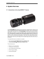
3.1. Introduction to the sharpVISION™ Camera
The sharpVISION™ digital cameras are high-resolution, high-performance cameras to be
used in industrial and scientific applications that include machine vision, microscopy and
Particle Image Velocimetry (PIV). The sharpVISION™ cameras are built around the scientific
grade SONY ICX sensors. The ICX are progressive scan, CCD interline solid-state sensors
with a square pixel array. Progressive scan allows all pixel signals to be output in about 1/12
sec. This chip features an electronic shutter with variable charge-storage time, which makes it
possible to realize full frame still-image without a mechanical shutter. High sensitivity and low
dark current are achieved through the adoption of HAD (Hole Accumulation Diode) sensors,
while low noise electronics provide highly linear and stable digital data at fast frame rates (12
frames/sec).
The sharpVISION camera is available in two models:
•
Non-cooled sharpVISION™ 1500-EX (Sony ICX285AL CCD).
•
Cooled sharpVISION™ 1500-EX (Sony ICX285AL CCD).
The main features are:
•
Binning 1x1, 2x2, 3x3 and 4x4.
•
Framing rate 12-40 frames/sec.
•
Up to 100 frames per second in ROI.
•
External trigger capability.
•
Synchronization signal.
sharpVISION™ User Manual
7
sharpVISION™ Digital Camera
•
Controlled exposure from 35 μsec up to 15 minutes in increments of 1μsec.
•
Fast inter-frame time (200 ns) for Particle Image Velocimetry applications.
•
12 bit digitizer (8 and 12 image bit depth).
These features make the sharpVISION digital cameras suitable for different applications:
•
Astronomy.
•
Microscopy.
•
Spectroscopy.
•
X-Ray Imaging.
•
Motion Analysis.
•
Biological Analysis.
•
Particle Image Velocimetry.
The sharpVISION™ cameras contain an IEEE-1394 (FireWire™, iLINK™) interface, which
offers true plug-and-play capabilities at a high-speed data transfer rate. The cameras are
provided with a software package that includes a Windows application, an ActiveX control,
a TWAIN driver and a software development kit which includes the complete Visual C++
source code of a working example of an image acquisition sample program to help you
integrate camera controls into custom applications, using the API supplied by IDT.
3.2. Note on cross-platform manual
The cross-platform manual provides instructions on using the sharpVISION digital camera on
the Windows and MAC OS/X platforms. The Windows and MAC icons below denote
differences in setup, procedures and commands between Windows and MAC users.
8
sharpVISION™ User Manual
sharpVISION™ Digital Camera
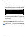
3.3. Software Development Kit
Upon the installation of the sharpVISION software package several options are available to
the user. These options are easily accessed via the Program menu under the Windows Start
button. The programs and associated files are organized under the IDT/sharpVISION folder.
This folder includes the example programs and the associated documentation. The software
components included in the sharpVISION Software Development Kit are listed below.
Component
Windows
MAC
sharpVISION™ stand-alone image acquisition application
Yes
Yes
SDK modules with example source code in C++.
Yes
Yes
ActiveX Control
Yes
No
TWAIN driver
Yes
No
Plug-in for LabVIEW™
Yes
No
Plug-in for MATLAB™
Yes
Yes
The sharpVISION™ SDK modules provide an API interface to develop applications to
operate the camera and access all the camera capabilities using a programming language
such as C++ and Java. A C/C++ header file is included in the SDK (sharpAPI.h file in the
Include sub-directory). A Visual Basic module is also included in the SDK (sharpAPI.bas file
in the Include sub-directory).
Most compiled languages can call functions; you will need to write your own
header/import/unit equivalent based on the C header file.
The sharpVISION driver is a DLL that resides in the system32 directory. A Visual C++ 6.0
stub library is provided (SharpDrv.lib in the Lib sub-directory); if you are using Visual C++,
link to SharpDrv.lib. Most other compilers can create a stub library for DLLs. The
sharpVISION DLL uses Windows standard calling conventions (_stdcall).
The MAC sharpVISION driver is a Framework that resides in the /Library/Frameworks
directory. If you are using Apple Project Builder 2.1 or XCode, add the
sharpVISION.framework to the project.
For a more detailed description of the SDK please refer to the sharpVISION SDK Reference.
sharpVISION™ User Manual
9
sharpVISION™ Digital Camera
4. Installing the sharpVISION™ camera
This section specifies the minimum recommended computer requirements and gives the
procedures needed to install the Camera Head, Camera Cable, Power Supply, I/O Cable,
and software.
4.1. Minimum computer requirements
PC
MAC
Operating System
Windows 2000, Windows XP
MAC OS X 10.2 (Jaguar) or higher
Processor
Pentium III or equivalent with 500
MHz processor.
G3 MAC OS X compatible
RAM
256 MB
256 MB
IEEE 1394 (fire-wire)
OHCI compliant IEEE 1394 card
OHCI compliant IEEE 1394 card
Hard Drive
40GB or greater hard drive
(recommended).
40GB or greater hard drive
(recommended).
Monitor/Colors
Capable of 1024 x 768 or greater
resolution (24/32 bit colors).
Capable of 1024 x 768 or greater
resolution. (24/32 bit colors).
Additional equipment
CDR drive (recommended).
CDR drive (recommended).
4.2. Package contents
Before beginning the installation process, check that the following items are present in the
sharpVISION™ package. If you are missing any of the items listed below, please contact IDT,
Inc. or your sales representative.
10
Camera.
I/O IEEE-1394 Cable.
Trigger cable.
CD-ROM of sharpVISION™ software and documentation.
sharpVISION™ Quick Start Guide.
sharpVISION™ User Manual
sharpVISION™ Digital Camera
4.3. Software Installation
Windows 2000/XP
Before installing the software make sure that the computer has Windows 2000 or Windows
XP installed as operating system.
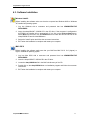
1. Log into Windows with a username and password that has ADMINISTRATIVE
PRIVILEGES.
2. Insert the sharpVISION™ VISION CD in the CD drive. If the computer is configured to
AUTORUN, the installer will run automatically. If not, click on the Windows Start button.
Select Run from the menu. Use the Browse button to locate the SETUP.EXE file on the
sharpVISION CD and click the OK button.
3. Select the “Install” option and follow the on-screen instructions.
4. EXIT when the installation is complete and restart your computer.
MAC OS/X
Before installing the software make sure that your MAC has MAC OS X 10.2 (Jaguar) or
higher, installed as operating system.
1. Log into Mac OS/X with a username and password that has ADMINISTRATIVE
PRIVILEGES.
2. Insert the sharpVISION™ VISION CD in the CD drive.
3. Locate the sharpVISION.sit file in the MAC sub-directory of the CD.
4. Double click on the sharpVISION.sit to run installation program and follow the on-screen
instructions.
5. EXIT when the installation is complete and restart your computer.
sharpVISION™ User Manual
11
sharpVISION™ Digital Camera
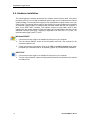
4.4. Hardware installation
The camera gets the necessary power from the computer via the fire-wire cable. If the power
provided by the PC is not enough an additional power supply unit is included with the camera
system package. The external power supply is only required when a laptop and/or a 6 to 4 pin
cable is used. The external power supply is also required for camera models that incorporate
an additional cooling module. All communication and data transfer with the host computer is
done via the IEEE 1394™ interface. This interface requires a single cable, which is also
supplied with the camera package. External triggering and synchronization are done via the
dedicated connector (PS2 type). Triggering is expected to be done with a TTL pulse. The
synchronization signal is also TTL level.
Windows 2000/XP
1. Connect the fire-wire cable to an available fire-wire port on your computer.
2. Turn the camera ON/OFF switch to the ON position and wait a few seconds for the
camera to initialize it self.
3. Follow the on-screen instructions. Click on the YES or Continue Anyway button when
prompted by the Windows 2000 or XP Operating system to proceed with the installation.
MAC OS/X
1. Connect the fire-wire cable to an available fire-wire port on your computer.
2. Turn the camera ON/OFF switch the ON position and wait a few seconds for the camera
to initialize it self.
12
sharpVISION™ User Manual
sharpVISION™ Digital Camera
IEEE-1394 Connectors
Power ON/OFF
Power
Connector
Trigger and
Sync Control
LED
4.5. Camera lens adapter
The camera is supplied with a standard C-mount. Alternatively, a C to F mount adapter is
available to interface with F-mount (Nikon type) lenses. Use Nikon lenses with a tilt/shift
capability when imaging at an angle. As an option, mounting hardware for tilt/shift lenses by
Canon is also available. Contact your IDT sales representative for ordering information.
sharpVISION™ User Manual
13
sharpVISION™ Digital Camera
5. sharpVISION™ stand-alone program
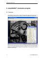
5.1. Overview
This application allows the user to acquire, save/play-back image records, and control the
camera in Single or Double Exposure modes. The GUI for the application is shown below.
Using the Camera Control dialog box, the user may interactively select the camera operating
modes as well as other parameters like exposure, binning, and so on. The user may also
start/stop the camera, acquire a sequence of images, store it to the hard disk as well as
control the record settings.
14
sharpVISION™ User Manual
sharpVISION™ Digital Camera
5.2. sharpVISION™ menu structure
The X-Vision main menu bar contains the following options:
File
Camera
View
Help
5.3. File Menu
The File menu contains the following options:
•
Save on the hard disk Images
•
Close the program and exit.
sharpVISION™ User Manual
15
sharpVISION™ Digital Camera
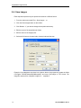
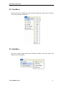
5.4. Save images
Each acquired sequence may be opened and saved in a different format.
1. From the main menu select File > Save Images… or
2. Click the Save Images button on the toolbar.
3. Click Browse... if you want to change the acquisitions directory.
4. Edit the name of the acquisition sub folder.
5. Edit the mane of the image prefix.
6. Select the file format, the start index, the stop index and the step.
Example: if the parameters are those in the picture above, the program will create the folder
C:\Program Files\IDT\sharpVISION\Acquis001 and store 100 images in TIFF format. The
image file names will be: Img000.tif, Img001.tif … Img099.tif.
16
sharpVISION™ User Manual
sharpVISION™ Digital Camera
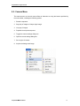
5.5. Camera Menu
The camera menu on the main menu offers an alternative to using the buttons provided by
the main toolbar, including the following options:
1. Record a sequence.
2. Stop play of images or Snap a single image.
3. Live play of images.
4. Playback the acquired sequence.
5. Toggle the camera settings dialog box.
6. Open the record settings dialog box.
7. Set a region of interest.
8. Acquire the background image.
sharpVISION™ User Manual
17
sharpVISION™ Digital Camera
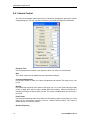
5.6. Camera Control
The camera configuration parameters may be interactively changed by opening the camera
settings dialog box. The user may set the camera in play mode and adjust the parameters.
Exposure Time
Use the f-stop buttons to select a new exposure value. The value is in microseconds
Rate
The current camera rate is updated any time a parameter changes.
Contrast and Brightness
Use the spin buttons to select new values of brightness and contrast. The range is from -100
to 100.
Binning
Use the Binning drop-down list to select a new value from 1x1 to 4x4. Pixels may be grouped
to form a larger pixel, which results in added SNR and sensitivity. When this parameter is
changed, the Region of Interest (ROI) is reset. The control is disabled when the camera is in
live mode.
Pixel Format
Use the Pixel Depth drop-down list to select from the following options: 8-bit (Gray 8) or 10-bit
(Gray 16) for monochrome cameras (12-bit for 1500-EX camera model). The control is
disabled when the camera is playing.
Readout Frequency
18
sharpVISION™ User Manual
sharpVISION™ Digital Camera
This parameter controls the speed at which the image data is read from the CCD. The
supported values are: 20 MHz, 10 MHz, 5 MHz and 2MHz.
Exposure Mode
Use the drop-down list to select either Single or Double exposure mode.
Trigger/Sync Mode
The default state of the camera at start-up is in the Internal/continuous mode. In this mode
the camera does not require a trigger input signal. The other camera modes (External Edge
High, Edge Low, Pulse High and Pulse Low) require an external trigger input. In these modes
the camera waits for a trigger signal to initiate the acquisition of a frame. There is a delay
(latency) between the trigger event and the start of an acquisition of 12 microseconds.
Camera Cooler
The camera cooler feature may be activated. The parameter enables and disables the
thermoelectric-cooler.
Acquisition Time Out
If the camera cannot snap a frame during live mode or cannot acquire a sequence, a time out
may occur. Type a new value into the text box to change the duration of the time out. The
value is displayed in seconds.
Region of interest
The camera ROI may be adjusted. The grayed edit boxes in the ROI group show the current
ROI settings. The user may change them by pressing the "Edit…" button (see below). The
button is disabled when the camera is playing.
Background
To reduce the noise associated to the sensor, a background image is acquired. The camera
lens cap must be on.
sharpVISION™ User Manual
19
sharpVISION™ Digital Camera
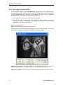
5.6.1. Set a region of interest (ROI)
The sharpVISION camera has a Partial Windowing capability that can be selected and set
via the software interface. Using this setting a region of interest for the image that is less than
the total available area of the sensor may be selected. This region can be interactively
adjusted and can occupy any area of the sensor’s active pixels.
1. Click on the Edit… button on the Camera Control dialog box.
2. From the Edit Region of Interest dialog box, select the ROI by setting the numerical
values for its origin and dimensions or by dragging the handles of the red box that
highlights the ROI within the sensor area.
Region of Interest options:
Reset: click the button to reset to the maximum value.
After the ROI is set, the selected region will appear in the main viewing window. To resize the
image to the screen area, select the Fit to Window from the main toolbar.
1300-DE: ROI boundaries occur on multiples of 16, although the maximum region for a
particular binning mode is not restricted to this rule. The minimum ROI is 16 x 16.
1400-DE and 1500-EX: they can do ROI on 4-pixel boundaries in width and 1-pixel in height.
20
sharpVISION™ User Manual
sharpVISION™ Digital Camera
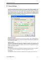
5.7. Record Settings
The Record Settings dialog box allows the user to select the recording parameters. The
images may be acquired directly to RAM or to the selected directory on the hard disk. When
images are recorded they are streamed to HOST RAM. The maximum number of images that
can be streamed at the video rate to HOST memory depends on the maximum system
capacity and the number that the user allows. When a longer record is required, the file
storage feature needs to be enabled. In this case the system acquires to RAM followed to a
write to disk until the desired record length is achieved.
Acquisitions directory
Browse to the directory of selections for saving acquired images. This is the parent directory
for the saved images. Each time the images are recorded a new sub-directory containing the
actual image files is created.
Samples / Images
The parameter indicates the total number of samples recorded in the acquisition. If the
camera is in double exposure modes, each sample is an image pair and the number of
images is two times the number of samples. If the camera is in single exposure mode,
samples and images correspond.
Memory Limit
This parameter limits the amount of RAM memory that can be used to acquire the images. If
the "System" value is set, the application reserves 50% of the system memory.
Free memory
The progress bar indicates the amount of available memory according to the memory limit.
sharpVISION™ User Manual
21
sharpVISION™ Digital Camera
Enable automatic save…
If this option is selected, the program stores the images to the hard disk immediately after the
acquisition.
Acquisition folder Name
The parameter indicates the directory in the hard disk where the acquired images will be
stored.
Images name prefix
Type the image prefix into the text box.
Images File Type
Use the drop-down list to set the image type format for archiving files to the hard drive of the
computer.
22
sharpVISION™ User Manual
sharpVISION™ Digital Camera
5.8. View Menu
Use the View menu to magnify the image, restore the original size (100% zoom) or compute
a zoom factor that fits in the window
5.9. Help Menu
This menu contains support options and information including: e-mail tech support and
software and manual updates.
sharpVISION™ User Manual
23
sharpVISION™ Digital Camera
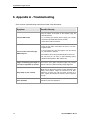
6. Appendix A - Troubleshooting
Some common troubleshooting scenarios are listed in the table below:
Symptom
Possible Remedy
Flip the switch at the back of the camera trying the
alternate position.
Camera LED not ON
Try connecting the auxiliary power supply (not normally
required if 6-pin IEEE1394 interface is used).
Check all the cable connections.
Check all the cable connections. Be sure to use IDTsupplied cables.
Cannot control camera through
IEEE-1394 port
Turn the camera off, close all programs, turn the camera
on, and restart the software.
Re-install the drivers and provided software from the CD.
Be sure that you are using a valid operating system
(Windows 98 2nd Edition, ME, 2000 or XP).
24
Image occasionally goes bright on
one side or stays dark on one side
Turn-off the room lights. Fluorescent lights may interact
with the camera to create fluctuating image brightness.
Hazy image or poor contrast.
Make sure the back focus plane is correctly adjusted to the
infinity focus position. Image the camera at a far field.
Adjust the C-mount ring until the image at infinity is in
focus. Tighten the setscrew to that the C-mount ring does
not slip.
Other problems
Call IDT for technical assistance.
sharpVISION™ User Manual
sharpVISION™ Digital Camera
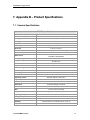
7. Appendix B – Product Specifications
7.1. Camera Specifications
1500-EX specifications
Total number of pixels
1434 x 1050
Number of active pixels
1360 x 1024 (1.4 million)
Binning modes
ROI (region of interest)
Exposure
Sensor type
Pixel Size
1x1, 2x2, 8x8
From 1x1 to full resolution
10 µs to 15 min (1 µs increments)
Sony IC285 progressive-scan interline CCD (mono)
6.45 µm x 6.45 µm
Linear full well
18.000 e (22.000 e with 2x2 binning)
Read out noise
8e
Dark current
Analog to Digital conversion
Image Bit Depth
Cooled: 0.15e/pix/s – Non-Cooled: doubles every 5 degrees
increase of temperature
12 bit
8/12 bit mono
Sensor size
Diagonal 11 mm
Aspect ratio
4:3
Anti-blooming
> 1000
Non linearity
< 1%
Cooling type
Peltier thermoelectric cooling to 25° C below ambient
Operating system
Digital interface
External sync
Gain/offset
Power requirements
Size
Weight
Operating Temperature
Storage Temperature
Lens Mount
Humidity
Tripod Mount
sharpVISION™ User Manual
Windows 2000, XP, MAC OS X
IEEE 1394 (fire-wire)
TTL
Programmable gain and offset
7 W (non cooled) 13 W (cooled); 8-24 V
76 x 63 x 132 mm (non cooled)
76 x 63 x 149 mm (cooled)
0.64 kg (non cooled); 0.92 kg (cooled)
0° to 50° C (32° to 122° F)
-10° to 60° C
C-mount, F-mount (Nikon and Cannon)
Less than 80% non condensing at 35° C (95° F)
Standard ¼-20 photo mounts
25
sharpVISION™ Digital Camera
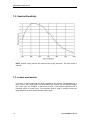
7.2. Spectral Sensitivity
NOTE: optional cooling reduces the thermal noise at long exposures. The dark current is
reduced.
7.3. Lenses and mounts
C–mount or F–mount lenses can be readily interfaced to the cameras. The standard lens is
Nikon 50 mm. Other focal lengths can be provided upon request. For Scheimpflug imaging
two mount types are available: a manual mount with a lens rotation adjustment and a
motorized mount for remote focus. The motorized mount is used to remotely control and
adjust both the lens focal distance and the rotation angle.
26
sharpVISION™ User Manual
sharpVISION™ Digital Camera
7.4. Trigger connector
The camera generates image data that is sent to the host interface via the IEEE-1394 cable.
The camera can be controlled from the host computer via this cable. The auxiliary power
supply provides power in those cases where power is unavailable from the host computer.
For example, when using a laptop computer as the host, the auxiliary power unit will usually
be required to power the camera TRIGGER/SYNC Control. The Trigger/Sync Control
connector at the rear of the camera is a 6 pin miniature circular DIN receptacle, AMD 749265.
The mating connector is Singatron Enterprises part number 6000-6P. The mating connector
is available from Digikey and can be purchased over the Internet at www.digikey.com.
The pin-out for the connector is as follows:
PIN #
Signal Name
Signal Source
Description
1
+5 VDC
User
Power for optocoupler trigger
2
Trigger (INPUT)
User
Active low trigger input
3
SYNC-A (OUTPUT)
Camera
Indicates CCD output (Active High)
4
GND
User
Ground reference for Optocoupler
5
SYNC-B (OUTPUT)
Camera
Exposure or Trigger Mask (Active High)
6
GND
User
Ground reference for Optocoupler
5 V DC (PIN #1) and GND (PIN #4 and PIN #6) must be connected in order for SYNC-A,
SYNC-B or TRIGGER to be live.
To use the camera with an external trigger source a TRIGGER/BUFFER INVERTER is
included. By means of an included trigger cable, this module supplies the camera with the
necessary conditioned trigger signals and power for pin 1 as well as it outputs the sync
signal. There is a 12-microsecond delay between the TRIGGER event and the beginning of
the exposure period. The Integration time corresponds to the length of time the CCD is
programmed to expose. The Readout time corresponds to the time to readout the CCD.
NOTE for PIV USERS: When the camera is used in the double-exposure mode the
exposure time must be set equal to the laser trigger delay minus 12 microseconds. The
second exposure is automatically set equal to the sensor read-out time.
sharpVISION™ User Manual
27
sharpVISION™ Digital Camera
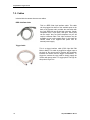
7.5. Cables
Included with the camera there are two cables:
IEEE 1394 Data Cable
This is a IEEE-1394 6-pin interface cable. This cable
can be plugged into either of the available ports at the
back of the camera and it provides the connection with
the 6-pin IEEE1394 port in the host computer. Certain
computers have a 4-pin IEEE 1394 port. These ports
can be used if they are OHCI-compliant, but you will
require a different cable. This 4-pin connector may be
available at your local computer store. In this case the
camera needs to be supplied with power from an
external power supply.
Trigger Cable
This is a trigger interface cable (PS/2 6-pin Mini DIN
Male to Male). This cable is plugged into trigger input at
the back of the camera and it provides the connection
between the camera and the trigger inverter/buffer. To
trigger the camera the user needs to simply supply the
inverter with power and a TTL trigger pulse. The logic for
this pulse is High-True
28
sharpVISION™ User Manual
sharpVISION™ Digital Camera
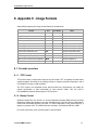
8. Appendix C - Image Formats
sharpVISION supports the image formats listed in the table below:
Format
Ext
Pixel Depth
Notes
Tagged Image File Format - TIFF™
TIF
8/16
Grayscale
Windows™ Bitmap
BMP
8
Grayscale
Portable network Graphics – PNG
PNG
8/16
Grayscale
Multi-Page TIFF
MPT
8/16
Grayscale
Multi-page Raw
MPR
8/16
Grayscale (IDT proprietary)
Multi-page Compressed
MCF
8/16
Grayscale (IDT proprietary)
Audio Video Interleaved (AVI)
AVI
8
Grayscale (standard codec)
Apple Quick Time (MOV)
MOV
8
Grayscale
Weinberger Sequence (BLD)
BLD
8
Grayscale
Moving Picture Experts Group (MPEG)
MPG
8
Grayscale (MPEG-1)
8.1. Formats overview
8.1.1. TIFF Format
TIFF pictures store a single raster image at any color depth. TIFF is arguably the most widely
supported graphic file format in the printing industry. It supports optional compression, and is
not suitable for viewing in Web browsers.
The TIFF format is an extensible format, which means that a programmer can modify the
original specification to add functionality or meet specific needs. This can lead to
incompatibilities between different types of TIFF pictures.
8.1.2. Bitmap Format
Windows bitmap files are stored in a device-independent bitmap (DIB) format that allows
Windows to display the bitmap on any type of display device. The term "device independent"
means that the bitmap specifies pixel color in a form independent of the method used by a
display to represent color. The default filename extension of a Windows DIB file is .BMP.
For further information, refer to the Microsoft™ documentation.
sharpVISION™ User Manual
29
sharpVISION™ Digital Camera
8.1.3. PNG Format
PNG is an extensible file format for the lossless, portable, well-compressed storage of raster
images. PNG provides a patent-free replacement for GIF and can also replace many
common uses of TIFF. Indexed-color, grayscale, and true-color images are supported, plus
an optional alpha channel. Sample depths range from 1 to 16 bits.
PNG is designed to work well in online viewing applications, such as the World Wide Web, so
it is fully streamable with a progressive display option. PNG is robust, providing both full file
integrity checking and simple detection of common transmission errors. Also, PNG can store
gamma and chromaticity data for improved color matching on heterogeneous platforms.
PNG is a platform-independent format that supports a high level of lossless compression,
alpha channel transparency, gamma correction, and interlacing. It is supported by more
recent Web browsers.
8.1.4. AVI Format
The Microsoft AVI file format is a Resource Interchange File Format (RIFF) file specification
used with applications that capture, edit, and play back audio-video sequences. In general,
AVI files contain multiple streams of different types of data. Most AVI sequences use both
audio and video streams. A simple variation for an AVI sequence uses video data and does
not require an audio stream.
8.1.5. MOV Format
The Apple Quick Time MOV file format is used with applications that capture, edit, and play
back audio-video sequences. In general, MOV files contain multiple streams of different types
of data. Most MOV sequences use both audio and video streams. A simple variation for an
MOV sequence uses video data and does not require an audio stream. The format is not
supported on Windows OS.
8.1.6. BLD Format
The BLD format corresponds to the file format RAW, which is known from several
applications. Each BLD file needs a corresponding descriptor file in the DSC format. In a BLD
file all single frames of an image sequence are stored successively uncompressed in the
block format. The data is in binary raw data format (e.g. for grayscale pictures 1 Byte per
Pixel). The descriptor file (DSC) belonging to the BLD file is a line-orientated ASCII file, in
which values like e.g. resolution, frames or date are stored. The DSC file can be created with
any text editor.
8.1.7. MPEG Format
MPEG, which stands for “Moving Picture Experts Group”, is a name of family standards used
for coding audio-visual in a digital compressed format. MPEG is a generic means of
compactly representing digital video and audio signals for consumer distribution. The basic
idea is to transform a stream of discrete samples into a bit-stream of tokens which takes less
space, but is just as filling to the eye. The graphic library implements the MPEG-1 format, the
standard on which such products as video CD and MP3 are based. The
compression/decompression technique implemented in MPEG is “lossy”, e.g. some amount
of data information is lost.
30
sharpVISION™ User Manual
sharpVISION™ Digital Camera
8.1.8. Multi-page Raw Format (MRF)
Multi-page Raw Format (MRF) is an uncompressed IDT proprietary file format. Multiple raster
images are stored in a single file. The format is described below.
Each MRF file contains a file header, an image header and an array of bytes that defines the
image data bits. The image raster data is not compressed and stored in the file “as it is”. Both
8 bit and 16 bit data are supported. The file structures are the following:
8.1.8.1. File header
A MRF file begins with a file header structure containing the IDT raw file signature.
typedef struct _RCFILE_HEADER
{
char szSign[8];
// IDT raw file signature
unsigned long nReserved;
// reserved
} RCFILE_HEADER, *PRCFILE_HEADER;
Members
szSign[8]: a 8 char buffer which contains the signature “IDT-MRF”. It indicates that the
remainder of the file contains a Multiple Raw File.
nReserved: this field is reserved for future use.
8.1.8.2. Image header
The file header is followed by the image header which contains general information about the
data stream.
typedef struct _RCIMG_HEADER
{
unsigned long nSize;
unsigned long nPages;
unsigned long nWidth;
unsigned long nHeight;
unsigned long nBPP;
unsigned long userData[64];
} RCIMG_HEADER, *PRCIMG_HEADER;
//
//
//
//
//
//
size of this header
number of pages/frames
image width
image height
bits per pixel
user data array
Members
nSize: size of the structure in bytes. It should be 84.
nPages: number of images contained in the file
sharpVISION™ User Manual
31
sharpVISION™ Digital Camera
nWidth: width of each image in pixels.
nHeight: height of each image in pixels.
nBPP: number of bits per pixels (8, 10 or12)
userData: an array of 64 unsigned long that may be user by the user to store other
information.
8.1.8.3. Data arrays
The image header is followed by the images data. Images are stored contiguously in
uncompressed format.
8.1.9. Multi-page Compressed Format (MCF)
Multi-page Compressed Format (MCF) is a compressed IDT proprietary file format. Multiple
raster images are stored in a single file. The format is described below.
Each MCF file contains a file header, an image header and an array of bytes that defines the
image data bits. The image raster data is compressed and stored in the file. Both 8 bit and 16
bit data are supported. The file structures are the following:
8.1.9.1. File header
A MRF file begins with a file header structure containing the IDT raw file signature.
typedef struct _RCFILE_HEADER
{
char szSign[8];
// IDT raw file signature
unsigned long nReserved;
// reserved
} RCFILE_HEADER, *PRCFILE_HEADER;
Members
szSign[8]: a 8 char buffer which contains the signature “IDT-MCF”. It indicates that the
remainder of the file contains a Multiple Compressed File.
nReserved: this field is reserved for future use.
8.1.9.2. Image header
The file header is followed by the image header which contains general information about the
data stream.
32
sharpVISION™ User Manual
sharpVISION™ Digital Camera
typedef struct _RCIMG_HEADER
{
unsigned long nSize;
unsigned long nPages;
unsigned long nWidth;
unsigned long nHeight;
unsigned long nBPP;
unsigned long userData[64];
} RCIMG_HEADER, *PRCIMG_HEADER;
//
//
//
//
//
//
size of this header
number of pages/frames
image width
image height
bits per pixel
user data array
Members
nSize: size of the structure in bytes. It should be 84.
nPages: number of images contained in the file
nWidth: width of each image in pixels.
nHeight: height of each image in pixels.
nBPP: number of bits per pixels (8, 10 or12)
userData: an array of 64 unsigned long that may be user by the user to store other
information.
8.1.9.3. Data arrays
The image header is followed by the images data. Images are stored contiguously in
compressed format. The first four bytes contains the size of the compressed buffer, followed
by image data.
Data compression is done using ZLIB library version 1.1.4, which is free and available for
download at the URL http://www.zlib.org.
The compression algorithm used by ZLIB is a variation of LZ77 (Lempel-Ziv 1977). It finds
duplicated strings in the input data. The second occurrence of a string is replaced by a
pointer to the previous string, in the form of a pair (distance, length). Distances are limited to
32K bytes, and lengths are limited to 258 bytes. When a string does not occur anywhere in
the previous 32K bytes, it is emitted as a sequence of literal bytes.
8.1.10.
Note on 16 bit grayscale formats
10-bit images acquired from the camera may be saved in different 16 bit formats. These
formats include TIF, PNG, MPT, MRF and MCF. Since 16 bit grayscale format is not a
standard, not all the applications for image processing may correctly display the saved
images.
sharpVISION™ User Manual
33