1
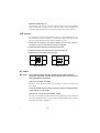
516-II DMX to 0-10 V
Converter
user manual
©1999 Martin Professional A/S, Denmark.
All rights reserved. No part of this manual may be
reproduced, in any form or by any means, without
permission in writing from Martin Professional A/S,
Denmark.
Printed in Denmark.
P/N 35000060, Rev. B
Thank you for selecting the Martin 516-II DMX to 0-10 V Converter. This device
converts the digital input from Martin and DMX protocol controllers to 0 - 10 V
output for use with analog lighting fixtures and other devices.
SAFETY
The 516-II DMX to 0-10 V Converter is not for household use. For safe operation,
read this manual before use and follow the safety precautions listed below. If you
have questions about how to operate the controller safely, please contact your
Martin distributor or dealer.
•
Disconnect the device from AC power before removing fuses or any part, and
when not in use.
•
Always ground (earth) the device electrically.
•
Use only a source of AC power that complies with local building and electrical
codes and has both overload and ground-fault protection.
•
•
Do not expose the converter to rain or moisture.
Never attempt to bypass fuses. Always replace defective fuses with ones of
the specified type and rating.
•
Refer any service operation not described in this manual to a qualified
technician.
•
3
Do not modify the converter or install other than genuine Martin parts.
Safety
SETUP
Unpacki ng
The 516-II DMX to 0-10 V Converter comes with the following items. Please
check the contents and verify that nothing is missing or damaged.
• 516-II DMX to 0-10 V Converter
• 5 meter 3-pin XLR data cable
• this user manual
Operati ng modes
OPERATING MODE OPTIONS
The 516-II DMX to 0-10 V Converter has 2 DMX modes and 1 Martin mode.
In DMX mode 1 the 516-II DMX to 0-10 V Converter performs as an analog
dimmer, converting 8-bit digital levels to voltages between 0 an 10 V. The
converter requires 16 DMX channels - 1 per output - in this mode.
In DMX mode 2 the 516-II DMX to 0-10 V Converter performs as a switch pack,
toggling devices on and off, by converting DMX signals to 0 or 10 V. The
converter requires just 2 DMX channels in mode 2 - each bit controls one output
channel.
In Martin mode the 516-II DMX to 0-10 V Converter performs as an analog
dimmer, as in DMX mode 1, but is for use with Martin RS-485 controllers such as
the 3032 and the 2308. The converter requires 1 Martin channel.
DMX MODE SETUP
The converter automatically switches to the selected DMX mode when used with
DMX controllers. The factory default is DMX mode 1, the dimmer mode. To
change DMX mode,
1 Disconnect the converter from power. Remove the top cover, which is
secured by 1 screw on each end and 3 screws on the back.
2 Locate the jumper at PL113 on the small circuit board.
3 To select DMX mode 2, place the jumper on pins 1 and 2. Pin 1 is marked and
is closest to the front panel. To select DMX mode 1, remove the jumper and
store it by placing on pin 1 only.
4 Replace the top cover before applying power.
4
Setup
MARTIN MODE SETUP
The converter automatically switches to Martin mode when used with Martin
protocol controllers. You may wish to swap the polarity of the serial data link
connectors as described below so they have the same pin-out as the controller.
XLR pi n- out
The converter’s serial data link sockets are factory set to the DMX pin-out. For
use with Martin protocol controllers, you can either switch the pin-out or use a
phase-reversing cable between the controller and the converter.
1 Disconnect the converter from power. Remove the top cover, which is
secured by 1 screw on each end and 3 screws on the back.
2 Locate the jumpers at PL112 on the small circuit board.
3 Position the jumpers as shown below for the desired pin-out.
-
2
+
Martin pin-out
3
3
+
2
4 Replace the top cover before applying power.
DMX pin-out
AC power
Warning!
For protection from electric shock, the converter must be
grounded (earthed). The AC mains supply shall have overload
and ground-fault protection.
CHECK VOLTAGE SETTING
Before use verify that the converter’s power supply is correctly set for the local
AC voltage.
•
Locate the 115/230 V selector switch on the back. Select the voltage that most
closely matches your AC supply.
INSTALL A PLUG ON THE MAINS LEAD
The converter’s mains lead must be fitted with a grounding-type cord cap that fits
your power distribution cable or outlet. Consult a qualified electrician if you have
any doubts about proper installation.
5
Setup
•
Following the cord cap manufacturer’s instructions, connect the yellow and
green wire to ground (earth), the brown wire to live, and the blue wire to
neutral. The table below shows some pin identification schemes.
Wire
Pin
Marking
Screw color
brown
live
“L”
yellow or brass
blue
neutral
“N”
silver
yellow/green
ground
green
Placement
The 516-II DMX to 0-10 V Converter fits into a 2U 19" rack mount. Alternatively,
you can place the converter on its rubber feet.
Analog devi ce connect ion
The 516-II DMX to 0-10 V Converter has 16 outputs for connecting 0-10 V
analog devices. Each output is connected to both a 5-pin DIN socket and the 25pin D-SUB socket: use the connector that fits your equipment. Devices may be
connected in parallel, using both types of connectors, for paired control of up to
32 devices. The pin number of each output is shown on the rear panel.
Connections can be tested without a controller by setting all pins on the
converter’s DIP-switch to the off position and then applying power to the
converter and the devices. The 516-II DMX to 0-10 V Converter applies 10 volts
to each output in a chase sequence.
Cont roller connect ion
The converters’s serial data link sockets are wired pin 1 to ground, pin 2 to signal
- (cold), and pin 3 to signal + (hot). They are compatible with DMX devices. For
compatibility with Martin RS-485 devices, pins 2 and 3 can be swapped. See
“XLR pin-out” on page 5.
1 For DMX operation, connect a data cable (included) to the controller’s data
output. If controller has a 5-pin output, use a 5-pin male to 3-pin female
adaptor cable (P/N 11820005).
2 For Martin operation, either (1) connect a phase-reversing cable (P/N
11820006) to the controller’s data output, or (2) connect a regular cable and
swap the polarity of the converter’s XLR connectors.
3 Lead the data cable from the controller to the 516-II DMX to 0-10 V Converter.
Plug the cable into the serial data link In socket.
4 Connect any additional converters or digitally-controlled fixtures output to
input (daisy-chain). When connecting 2 fixtures with reversed polarity, insert
6
Setup
a phase-reversing cable between them. Up to 32 devices may be connected
on a serial link.
5 Terminate the link by inserting a male termination plug (P/N 91613017) into
the data output of the last device. A termination plug is simply an XLR
connector with a 120 ohm, 0.25 W resistor soldered across pins 2 and 3.
Male
Termination Plug
Male XLR
1
2
3
120
P/N 91613017
5-pin to 3-pin
Adaptor
3-pin to 5-pin
Adaptor
Male
Female
Male
Female
Male
Female
1
2
3
4
5
1
2
3
1
2
3
1
2
3
4
5
1
2
3
1
2
3
P/N 11820005
3-pin to 3-pin
Phase-Reversing
Adaptor
P/N 11820004
P/N 11820006
Address select ion
A control address must be set using the DIP-switch on the rear panel. The control
address, also known as the start channel, is the first channel used to receive
instructions from the controller.
Each converter must be assigned its own address and non-overlapping control
channels for individual control. The 516-II DMX to 0-10 V Converter uses 2 or 16
DMX channels, depending on mode, or 1 Martin channel.
1 Disconnect the converter from AC power.
2 Select an address for the converter on your controller. The highest allowable
address is 497 in DMX mode 1, 511 in DMX mode 2, and 32 in Martin mode.
3 Look up the DIP-switch setting for the address on page 8.
4 Set pins 1 through 10 to the ON (1) or OFF (0) position as listed in the table.
7
Setup
DIP-SWITCH ADDRESS TABLE
Find the address in the table below. Read the settings for pins 1 - 5 to the left and
read the settings for pins 6 - 10 above the address. “0” means OFF and “1” means
ON. Pin 10 is always off.
DIP-Switch Setting
#1
0
1
0
1
0
1
0
1
0
1
0
1
0
1
0
1
0
1
0
1
0
1
0
1
0
1
0
1
0
1
0
1
8
0 = OFF
1 = ON
#2 #3 #4
0
0
0
0
0
0
1
0
0
1
0
0
0
1
0
0
1
0
1
1
0
1
1
0
0
0
1
0
0
1
1
0
1
1
0
1
0
1
1
0
1
1
1
1
1
1
1
1
0
0
0
0
0
0
1
0
0
1
0
0
0
1
0
0
1
0
1
1
0
1
1
0
0
0
1
0
0
1
1
0
1
1
0
1
0
1
1
0
1
1
1
1
1
1
1
1
#5
0
0
0
0
0
0
0
0
0
0
0
0
0
0
0
0
1
1
1
1
1
1
1
1
1
1
1
1
1
1
1
1
#10
#9
#8
#7
#6
0
0
0
0
0
0
0
0
0
1
0
0
0
1
0
0
0
0
1
1
0
0
1
0
0
0
0
1
0
1
0
0
1
1
0
0
0
1
1
1
0
1
0
0
0
0
1
0
0
1
0
1
0
1
0
0
1
0
1
1
0
1
1
0
0
0
1
1
0
1
0
1
1
1
0
0
1
1
1
1
1
2
3
4
5
6
7
8
9
10
11
12
13
14
15
16
17
18
19
20
21
22
23
24
25
26
27
28
29
30
31
32
33
34
35
36
37
38
39
40
41
42
43
44
45
46
47
48
49
50
51
52
53
54
55
56
57
58
59
60
61
62
63
64
65
66
67
68
69
70
71
72
73
74
75
76
77
78
79
80
81
82
83
84
85
86
87
88
89
90
91
92
93
94
95
96
97
98
99
100
101
102
103
104
105
106
107
108
109
110
111
112
113
114
115
116
117
118
119
120
121
122
123
124
125
126
127
128
129
130
131
132
133
134
135
136
137
138
139
140
141
142
143
144
145
146
147
148
149
150
151
152
153
154
155
156
157
158
159
160
161
162
163
164
165
166
167
168
169
170
171
172
173
174
175
176
177
178
179
180
181
182
183
184
185
186
187
188
189
190
191
192
193
194
195
196
197
198
199
200
201
202
203
204
205
206
207
208
209
210
211
212
213
214
215
216
217
218
219
220
221
222
223
224
225
226
227
228
229
230
231
232
233
234
235
236
237
238
239
240
241
242
243
244
245
246
247
248
249
250
251
252
253
254
255
256
257
258
259
260
261
262
263
264
265
266
267
268
269
270
271
272
273
274
275
276
277
278
279
280
281
282
283
284
285
286
287
288
289
290
291
292
293
294
295
296
297
298
299
300
301
302
303
304
305
306
307
308
309
310
311
312
313
314
315
316
317
318
319
320
321
322
323
324
325
326
327
328
329
330
331
332
333
334
335
336
337
338
339
340
341
342
343
344
345
346
347
348
349
350
351
352
353
354
355
356
357
358
359
360
361
362
363
364
365
366
367
368
369
370
371
372
373
374
375
376
377
378
379
380
381
382
383
384
385
386
387
388
389
390
391
392
393
394
395
396
397
398
399
400
401
402
403
404
405
406
407
408
409
410
411
412
413
414
415
416
417
418
419
420
421
422
423
424
425
426
427
428
429
430
431
432
433
434
435
436
437
438
439
440
441
442
443
444
445
446
447
448
449
450
451
452
453
454
455
456
457
458
459
460
461
462
463
464
465
466
467
468
469
470
471
472
473
474
475
476
477
478
479
480
481
482
483
484
485
486
487
488
489
490
491
492
493
494
495
496
497
498
499
500
501
502
503
504
505
506
507
508
509
510
511
Setup
OPERATION
The 516-II DMX to 0-10 V Converter is ready to operate when
• the DMX mode is selected,
• the voltage setting (115/230 V) is correct,
• a plug has been installed on the power cable and the power cable is plugged in,
• the controller and analog devices are connected and plugged in,
• the control address is set on the DIP-switch.
Martin mode operat ion
1 Flip the power switch on the front panel of the converter to ON. Apply power
to the controller and the analog devices.
2 Set levels for the analog devices as described in the controller user manual.
DMX dimmer operat ion
1 Flip the power switch on the front panel of the converter to ON. Apply power
to the controller and the analog devices.
2 Set levels for the analog devices by accessing the converter on the DMX
controller and setting the corresponding channels between 0 and 255. The
relationship between voltage and DMX level is shown below: values are
approximate.
9
9ROWV
3
4
5
6
7
8
9
:
'0;
3
58
83
:8
433
458
483
4:8
Operation
;
533
<
558
43
583
DMX swit ch pack operat ion
1 Turn on the converter, controller, and analog devices.
2 Toggle devices 1 - 8 on/off by setting channel 1 as shown below. For example,
to turn devices 1, 2, 3, 4 on and devices 5, 6, 7, 8 off, set channel 1 to 240.
3 Similarly, use channel 2 to control devices 9 - 16.
DMX Mode 2
Channel 1
• = On
4
5
6
7
;
:
9
8
•
•
•
•
•
•
•
•
•
•
•
•
•
•
•
•
•
•
•
•
•
•
•
•
•
•
•
•
•
DMX Mode 2
Channel 2
• = On
<
43
44
45
•
•
•
•
•
•
•
•
•
•
•
•
•
•
•
10
•
•
•
•
•
•
•
•
•
•
•
•
•
•
•
•
•
•
•
•
•
•
3
49
65
7;
97
;3
<9
445
45;
477
493
4:9
4<5
53;
557
573
•
•
•
•
49
48
47
46
4
4:
66
7<
98
;4
<:
446
45<
478
494
4::
4<6
53<
558
574
5
4;
67
83
99
;5
<;
447
463
479
495
4:;
4<7
543
559
575
6
4<
68
84
9:
;6
<<
448
464
47:
496
4:<
4<8
544
55:
576
•
•
•
•
7
53
68
85
9;
;7
433
449
465
47;
497
4;3
4<9
545
55;
577
4
4:
66
7<
98
;4
<:
446
45<
478
494
4::
4<6
53<
558
574
5
4;
67
83
99
;5
<;
447
463
479
495
4:;
4<7
543
559
575
6
4<
68
84
9:
;6
<<
448
464
47:
496
4:<
4<8
544
55:
576
8
54
6:
86
9<
;8
434
44:
466
47<
498
4;4
4<:
546
55<
578
7
53
68
85
9;
;7
433
449
465
47;
497
4;3
4<9
545
55;
577
•
8
54
6:
86
9<
;8
434
44:
466
47<
498
4;4
4<:
546
55<
578
Operation
•
•
•
9
55
6;
87
:3
;9
435
44;
467
483
499
4;5
4<;
547
563
579
:
56
6<
88
:4
;:
436
44<
468
484
49:
4;6
4<<
548
564
57:
•
•
•
•
•
•
•
3
49
65
7;
97
;3
<9
445
45;
477
493
4:9
4<5
53;
557
573
•
•
•
9
55
6;
87
:3
;9
435
44;
467
483
499
4;5
4<;
547
563
579
:
56
6<
88
:4
;:
436
44<
468
484
49:
4;6
4<<
548
564
57:
•
•
•
•
•
•
•
•
•
•
•
•
•
•
•
•
•
•
•
•
;
57
73
89
:5
;;
437
453
469
485
49;
4;7
533
549
565
57;
<
58
74
8:
:6
;<
438
454
46:
486
49<
4;8
534
54:
566
57<
43
59
75
8;
:7
<3
439
455
46;
487
4:3
4;9
535
54;
567
583
44
5:
76
8<
:8
<4
43:
456
46<
488
4:4
4;:
536
54<
568
584
45
5;
77
93
:9
<5
43;
457
473
489
4:5
4;;
537
553
569
585
46
5<
78
94
::
<6
43<
458
474
48:
4:6
4;<
538
554
56:
586
47
63
79
95
:;
<7
443
459
475
48;
4:7
4<3
539
555
56;
587
48
64
7:
96
:<
<8
444
45:
476
48<
4:8
4<4
53:
556
56<
588
•
•
•
•
•
•
•
48
64
7:
96
:<
<8
444
45:
476
48<
4:8
4<4
53:
556
56<
588
•
•
•
•
•
•
•
•
•
•
•
•
•
;
57
73
89
:5
;;
437
453
469
485
49;
4;7
533
549
565
57;
<
58
74
8:
:6
;<
438
454
46:
486
49<
4;8
534
54:
566
57<
43
59
75
8;
:7
<3
439
455
46;
487
4:3
4;9
535
54;
567
583
44
5:
76
8<
:8
<4
43:
456
46<
488
4:4
4;:
536
54<
568
584
45
5;
77
93
:9
<5
43;
457
473
489
4:5
4;;
537
553
569
585
46
5<
78
94
::
<6
43<
458
474
48:
4:6
4;<
538
554
56:
586
47
63
79
95
:;
<7
443
459
475
48;
4:7
4<3
539
555
56;
587
SPECIFICATIONS
DIMENSIONS
Length . . . . . . . . . . . . . . . . . . . . . . . . . . . . . . . . . . . . . . . . . . . . . . . . . . . . . 482 mm (19.0 in)
Width. . . . . . . . . . . . . . . . . . . . . . . . . . . . . . . . . . . . . . . . . . . . . . . . . . . . . . . 125 mm (4.9 in)
Height . . . . . . . . . . . . . . . . . . . . . . . . . . . . . . . . . . . . . . . . . . . . . . . . . . . . . . . 89 mm (3.5 in)
Weight . . . . . . . . . . . . . . . . . . . . . . . . . . . . . . . . . . . . . . . . . . . . . . . . . . . . . . . . 2.8 kg (6.1 lb)
ELECTRICAL
Power supply settings . . . . . . . . . . . . . . . . . . . . . . . . . . . . . . . . .115/230 V, switch selectable
AC frequency . . . . . . . . . . . . . . . . . . . . . . . . . . . . . . . . . . . . . . . . . . . . . . . . . . . . . 50 - 60 Hz
Power consumption. . . . . . . . . . . . . . . . . . . . . . . . . . . . . . . . . . . . . . . . . . . . . . . . . . . . . 10 W
Primary fuse . . . . . . . . . . . . . . . . . . . . . . . . . . . . . . . . . . . . . . . T 125 mA, 250 V, 5 x 20 mm
Secondary fuse . . . . . . . . . . . . . . . . . . . . . . . . . . . . . . . . . . . . . . . . T 2 A, 250 V, 5 x 20 mm
CONSTRUCTION
Housing . . . . . . . . . . . . . . . . . . . . . . . . . . . . . . . . . . . . . . . . . . . . . . . . . . . . . . . . . . . . . . .steel
Finish. . . . . . . . . . . . . . . . . . . . . . . . . . . . . . . . . . . . . . . . .black, electrostatic powder coating
CONNECTIONS
Serial data in . . . . . . . . . . . . . . . . . . . . . . . . . . . . . 3-pin XLR male, pins 2 and 3 switchable
Serial data out . . . . . . . . . . . . . . . . . . . . . . . . . . 3-pin XLR female, pins 2 and 3 switchable
Analog output . . . . . . . . . . . . . . . . . . . . . . . . . . . . . . . 5-pin DIN female, 25-pin DSUB male
11
Specifications