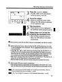
1
Canon
MACRO RING LITE
MR-14EX
MACRO TWIN LITE
MT-24EX
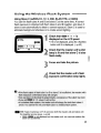
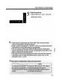
Thank you for purchasing a Canon product.
The Canon Macro Ring Lite MR-14EXlMacro Twin Lite MT-24EX are flash
units for closeup photography. They have many high-end features such as
the E-TTL (Evaluative-TTL) autoflash system.
The available features depend on the type of EOS camera you use with
the MR-14EXlMacro Twin Lite MT-24EX. Refer to the tables below to confirm your EOS camera type and the MR-14EXlMT-24EX features which are
compatible with your camera.
This instructions booklet has separate sections for Type-A and Type-B
EOS cameras. Read Chapter 1 which applies to all cameras, then read the
respective chapters which apply to your camera type.
Type-A Cameras
EOS-1 D, 1V, 3, D30, ELAN 7/7E, 30/33,
E-TTL ELAN II/ELAN II E, SO/SOE, REBEL 2000/300,
REBEL G, SOON, 3000N/66, IX, IX 7/IX Lite
Type-B Cameras
TTL
All EOS cameras other than the above.
MR-14EXlMT-24EX Features Available with EOS Cameras
0: Available X: Not available
Features
With Type-A Cameras
With Type-B. Cameras
E-TIL autoflash
0
X
TTL autoftash
O'
0
High-speed sync (FP flash)
0
0
0
0
X
X
FE lock
FEB (Flash exposure bracketing)
Wireless, multi-Speedlite E-TTL
0
X
'With C.Fn-3-1 .
• Key to Symbols
U The Caution symbol alerts you to actions to prevent flash
photography problems.
[lJ
The Note symbol gives additional information for basic operations.
~~~
The Light bulb symbol offers helpful tips for operating the Macro
Ring Lite or for taking pictures.
Keep this Instructions booklet handy for future reference.
2
Abol.Jt·Macro.TwiRt.ite.MT~24EXlllstructlons
TheonIY~differencepetwean~acrof3ing4iteMR-149)(~ndMacro
Twin LiteMT..24EXistheJlash tube/heads and ~fewfe'atures.. This
instructi9D§bookletcenterson. theMH-1AEXandmost of the
instr~ctionsalso'appltt?th~fv1T~~4~)( ..Instructionswhi?h·applyonly
tott:JeMT..?4~Xar~rin .Cl.sePC1rCl.t~(Jhapter.·lf.y9u. havetheMT-24EX,
rea.dupt<lpage5,then rea.dpa~es7!)to85:.·Allot~er instructions.· (on
pages? ·.to 73)fortheMT~24EXarethesameasforthe·. MR.. 14EX.
~p~.t~~$~t~i$~~~l(let
IfY(jUit"lC3.,,~a:rype-~.·e~'n1·~r<l,~¢~9;pag~si~·t()•. 4fi~ndi64t9". 73,'. 'If
YOU•• h~;} • a • JypeS~ccaJera:, . t;sd~ig7s9 •. t020ard49t~.'73 •.
ti . "ThE?op~rCl!i9PHr8PE:}tf~r~~assyrTletf1at tti. e.·SC1I1"l~ra.C3.nd . • the
rv1R.;!4E?</~-r: .. g~·~Xa~~1~.lreadY.turned·on .•. ·Bef()Feproeeeding,
be suretotwno0fhernainswitch. .
...' ' '
• .Theicon$usedinthetextarethesame ones found on the
carn~raangthe MR-14EXlfv1T.;24EX's buttons and settings•.
For the name of thErbottOh ordial, see "NomenClature" on
pages6to 8 and 76.
Icons for the camera's shooting modes. are. as follows:
o : FoJI Auto
Tv : Shutter..priority AE
:ProgramAE
M: Manual
Av :.Aperture:priorityAE
P
• The (~a}and(~12)icons indicate that the function remains in
effecUor8 sec. and 12 sec. respectively after the relevant
button is released.
• Heferenc~pagenumbersareindicat~in parentheses as
follbWS:{7p...)
.····The~icC)rl.·brings attention to a' sirllpledescription. of the
resp~cti\,~~u~tom .• Function~.For.adetCitled~xplanati.on. of the
CustO~1~~n~tipnJ·.·r~e.~9~st(.)mFupcti()I1~"{)1'l8?weS\ . ·.~4 and. 83.
'·Th~j~~~r~~ti~l'l~'jn'~h~~· •. . bOt:)~tE}t~~~urne.th~tthes tandard· ",'
C
.• . . . . . ·.u:,s.•. . •.t·.Q'.. .•. 'm:iElil~~Qm$i$ttJngs
.• arein.effe.ct
. · --'
.
':::.('.:-> '.' ',-' ,-,,:'-:,:. -:": ,:-:- ,',,':::, "": '-'. ',:,: :-:' : ,': -'. '.,' .:"',:' :".-.' .:
....
:(. -'.'.:'/<:;,::',::'::,::-":-: ~:":' ,'-'-.-: "\:'::";"'-':~:-'::-::-:~:::Y:
':/:':"'" :"','::
3
About Macro Twin Lite MT-24EX Instructions
How to Use this Booklet
Nomenclature
3
3
6
1 Before You Start (Type-A Cameras,"-ype-B Cameras). ...9
Installing Batteries
External Power Sources
Attaching the Control Unit to the Camera
Attaching the Flash Ring
Main Switch
Pilot Lamp and Test Firing
Flash Exposure Confirmation
Flash Range
Flash Mode
Setting the Film Speed
LCD Panel Illumination
Focusing Lamp
Resetting to the Default Settings
10
12
13
14
15
16
16
17
19
19
19
20
20
Using Flash with the Camera's Shooting Modes
22
3 Advanced Flash RhotographV (Type-A Cameras).
~tD at: Selecting the Flash Tube
Modeling Flash
FE Lock
~ Flash Exposure Compensation
~ FEB (Flash Exposure Bracketing)
GIl High-Speed Sync (FP Flash)
M Manual Flash Mode
~ Second-Curtain Synchronization
4
25
26
29
30
32
34
36
38
40
Contents
Setting Up a Wireless Flash System
Using the Wireless Flash System
S
Basic Flash Photography
50
~.D
Flash Exposure Compensation
FEB (Flash Exposure Bracketing)
M Manual Flash Mode
1::1> Second-Curtain Synchronization
Wireless Manual Flash
54
56
58
60
62
63
~ Custom Functions
MR-14EX/MT-24EX System
Troubleshooting Guide
Specifications
Feature Availability Table
64
66
68
69
72
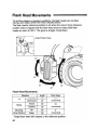
at: Selecting the Flash Tube
Macro "fwin Ilite M"f-24.EX Features .....•.........................'75
Nomenclature
Attaching the Flash Heads
Flash Head Movements
Flash Distance Range
~ Custom Functions
Major Specifications
~
..
4.9
Using Flash with the Camera's Shooting Modes
~
~
I
r ype-B Cameras~
42
45
76
77
80
83
83
84
iI
5
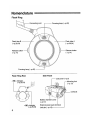
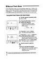
Nomenclature _ _IIJ1IllI.I88IlfIjfllllllllllll._JlllJlJfIIIIIIJIIII_ _1IJ1JA
Flash Ring
c-
Connecting cor_d_:_-:_- - Focusing lamp (--7p.20)
r-
Flash tube B ----.....;!-(--7p.26,54)
-:.:::----- Flash tube A
(--7p.26,54)
Release button - (--7p.14)
Flash Ring Rear
Release button
(--7p.14)
Side Panel
LCD panel (--7p.8)
< ~ > indicator
--7 P.26,54)
Mounting foot
(--7p.13)
L:r:s,
~
@
Battery chamber cover
(--7p.10)
< ~ >indicator
(--7p.26,54)
6
External power pack terminal
Lock pin (--7p.13)--------'
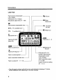
Nomenclature
Control Unit
< MODE> flash mode button • Loops in the following sequence:
C·
r - - - -
-1- - - -
:
1
ETTL / TTL ---. M ~
< ~ > High-speed sync
(FP flash) button (~p.36)
< t:l> > 2nd curtain sync button
:1
~
_
(~p.40,62)
When these two buttons are
pressed simultaneously, the setting
changes in the following loop:
1
:
:
*<:!?:-> LCD panel illumination-}I-'----l~ ~ eD ~ ~_
button (~p.19)
I
~ (OFF)~
<C.Fn>Custom Function
button(~p.64)
1r
_111-_i
----+--~--
*<+> Increment button
~_. _.• _ . _ .....-.-.;
:~\\\
...." ---'' - *< -
> Decrement button
~..!...!--*<SEUSET>
Select/Set button
:t>.:.( .Fn
+
M( DE
-
SEL SET
®~®
-----*U-:-'-----,I
....::L~:;:..:.~~J
I
CD.
< <J > button
...-:I:--......-:l
LAMP
<LAMP>----++--© ~
Focusing lamp bUtlOnl-7po20)1 \
<PILOT>
Pilot lamp (~p.16)
Test firing button (~p.16)
• Uniform modeling flash
(~p.55)
• SE cancel (~p.15,44)
PILOT
©
- - - - + + - - < C> > button
®
RATIO
OFF O.NrSE
(Q)
LI-----!~_ < CH. >( :~~2;)el button
~_-----..
(~p.13) -
Flash exposure confirmation lamp
(~p.16)
II
~
C __
____
~
~
L....-
Locking collar
CH.
~.
Main switch
(~p.15)
""-1
<RATIO>
Flash ratio control/Flash tube
switching button
(~p.26, 39, 42, 54, 61)
7
Nomenclature
LCD Panel
Flash exposure compensation - - - -.......
(-3 to +3 stops)
FEB amount (-3 to +3 stops)
Manual flash output level (1/1 - 1164)
, - - - - - - - - ~ FEB icon
r - - - - - - - - - (fi Custom
Function icon
Flash exposure compensation icon
,....----- t:I>
ETTL E-TT.L autoflash iCOi
TTL
M
sync icon
TTL autoflash icon
'
~
ManualflaShiconi.
Flash tube 10 (AlB)
Slave 10 (C)
• •••
ETTL
Ii
GIl
FP flash icon
11111__
~
LlLM
+B BIBB
11I
~
~I
~~ Channel
~ No. (1 - 4)
(6 1 2 3 4
j----_.
mamllA: ~: ~I+B BIBB
,. - 4:1- 2:1-1:1
._11-1:2 -1:4 -1:811.~
\1...
~.D8:1-
~
IiBmlratio control icon
Flash
2nd-curtain
~ at: Flash tube B
firing icon
~~D
Flash tube A firing icon
Flash ratio scale segment ------'
AlBIC manual flash indicator bar------'
Flash ratio scale (8:1 - 1:1 - 1:8) ---------I
- - FEB status (Fb-1 to 3)
SLAVE C flash exposure
compensation amount
(-3 to +3 stops)
AlBIC manual flash output
(1/1 to 1164)
Custom Function Nc>.Isetting
(F1-7,O,1)
• The LCD panel is shown with all the icons and indications displayed. The items
actually displayed differ depending on the flash settings.
8
Learn how to prepare the Macro Ring
Lite MR-14EX for actual use.
Before You Start
Macro Ring Lite MR-14EX requires one of the following two types of
batteries:
(1) Four size-AA alkaline batteries
(2) Four size-AA nickel-hydride batteries
Slide the battery compartment
cover as shown by the arrow and
flip it up.
Insert the batteries.
• Make sure the + and - battery
contacts are properly oriented as
shown in the battery chamber.
Close the battery chamber cover
as shown in the diagram.
10
Inr;:,t<:lllinn
Ill.• usef8~rpewbatteri~softhesame
Batteries
type.. When replacing batteries, replace all
fou.rb~tten~~at gne time.
.SiZE)"AAJithiurnb~tteries c:an· also be used.
.-AltholJ9h 1l0n-aJkaline, manganese batteries may also be used, the number of
flashes Will be less.
• H~rrl0vethebatte.rieswheh the Macro Ring Lite MR-14EX will notbe used for
anextended.period.
-In low temperatures, take two set50f batteries and keepone setwarm in a
pocket, etc:, and use the batteries alternately.
o. To preveQtfaultyconnections, make sure the battery contacts are clean. If
.
necessary, use a dean cloth to wipe the battery contacts,
• In the case ofs.ize-AA •nickel-hydride and size-AA lithium batteries, the· shape
of the contacts is not standardized. Be sure that the batteries are compatible
with the flash unit before buying.
Recycling Time and Flash Count
(Applicable to both or only one flash tube firing)
Battery Type
Recycling Time
Flash Count
Size-AA alkaline batteries
Approx. 0.1-7 sec.
Approx. 120 to 800
• The minimum recycling time applies in the E-TTL or TTL mode while the
maximum recycling time applies in the manual or full-output (1/1) mode.
• The minimum flash count applies in the manual or full-output (1/1) mode
while the maximum flash count applies in the E-TIL or TIL mode.
• The above specifications are based on Canon's testing standards.
• Using size-AA nickel-hydride batteries will yield only about 70 to 80
percent of the flashes (1550 mAh at full output) obtainable with size-AA
alkaline batteries. The recycling time will also be about half the time with
size-AA alkaline batteries.
11
I
External Power Sources
~~1
Macro Ring Lite MR-14EX can use either of the following two external
power packs. For details on the power pack, refer to the Instructions of the
respective power pack.
(1) Compact Battery Pack CP-E2
Uses six size-AA alkaline, nickel-hydride, or lithium batteries.
(2) Transistor Pack E
Uses Battery Magazine TP (six size-C alkaline batteries) or Ni-Cd
Pack TP.
Recycling Time and Flash Count
(Applicable to both or only one flash tube tiring)
Power Source
Internal Power
Sources
Size-AA alkaline batteries
Compact Battery Pack CP-E2
(w/alkaline batteries)
External Power
Sources
Transistor Pack E (w/alkaline batteries)
Transistor Pack E (wiN i-Cd Pack TP)
Recycling
Time (sec.)
Flash Count
Approx.0.1-7
Approx.120-800
Approx.0.1-4
Approx, 400-2500
Approx.0.1-4
Approx. 400-2500
Approx. 0.1-3
Approx. 330-2000
• The minimum recycling time applies in the E-TTL or TIL mode while the
maximum recycling time applies in the manual or full-output (1/1) mode.
• The minimum flash count applies in the manual or full-output (1/1) mode
while the maximum flash count applies in the E-TIL or TTL mode.
• The above specifications are based on Canon's testing standards .
. . -Evenwhen an~xternal power source is used, batteries must still be installed in
tbeMR-14EX to power its internal circuitry.
-TheMR-14EX uses both the internal and external power sources to recycle
the flash. Therefore,. the. internalpower source. maybecome exhausted sooner
thanthe externalpow~rso~rce. ForproI5m~edflash· photography,keep a spare
set of· size-AA batteries handy fortheinternal. power source.
12
Attaching the Control Unit to the Camera ",. ...
Loosen the locking collar by
turning it as shown by the arrow.
Slip the Control Unit's mounting
foot into the camera's hot shoe all
the way.
Turn the locking collar as shown
by the arrow and tighten.
~
The mounting foot's locking pin will
also extend into the hot shoe.
• To detach the Control Unit, turn the
locking collar in the opposite direction
until it stops. (The locking pin retracts
into the mounting foot.) Then slip it
off the hot shoe.
13
I
Attaching the Flash Ring
.IIIIIII'IlJIJIII.IIIJIII'. . . . .1IJJIJIJ1lf1J
The Macro Ring Lite MR-14EX can be attached directly to the following
lenses: EF 50mm f/2.5 COMPACT MACRO, EF 100mm f/2.8 MACRO
USM, EF 100mm f/2.8 MACRO, and MP-E 65mm f/2.8 1-5x lenses. To
attach it to the EF 180mm f/3.5L MACRO USM, the Macro Lite Adapter
72C"(sold separately) is required.
Press the release buttons on both
sides of the flash ring.
• Keep pressing both release buttons.
Attach the flash ring to the Macro
Ring Lite mount on the front of
the lens.
• Let go of the release buttons and
make sure the flash ring is securely
attached to the front of the lens.
• The flash ring can rotate 360
degrees.
• To detach the flash ring, follow this
procedure in reverse.
Attaching the Macro Lite Adapter 72C
Screw on the Macro Lite Adapter 72C
onto the front of the EF 180mm f/3.5L
MACRO USM lens.
14
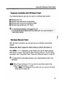
The main switch has three settings as shown below.
I
Turns off the power.
OFF,O.N rSE
«JIIIr»
mum)
Turns on the power.
OFF,O.N rSE
OFF,O.N rSE
Turns on the power and enables
the SE mode.
.. To save battery power, the SE (Save
Energy) mode turns off the Macro
Ring Lite automatically after 90 sec.
of non-use.
• To cancel the SE mode, press the
test firing button.
~~~ Mel110ryfeature
The·.MacroRi~g
Lite'scurrentfl(l$h•• mode~flashexposurecompensationsetting,
etc.. ,.. are. retaineci.in memoryeyenafterit. is turn~doff.Wtienthe ~acroBingLite
jsturf)ecionagain,.allth8:settin?s.winstjUbejn•. effect.·\I\Ih~nxo~replacethe
batteries{Y()119(lnret~n.tf:1I;l • settingsi!Yol,I·. insta:Une'lllb.~tterie$·within90sec,
15
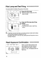
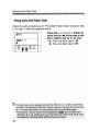
This tests whether the Macro Ring Lite can fire a flash.
Check the Pilot lamp.
• When the flash is ready, the Pilot
lamp will light.
Press the Pilot lamp (test firing
button).
~ A flash will fire.
• The Pilot lamp is also a test firing
button.
I.lI •A test flash cannot be fired after you press the camera's shutter button halfway
and the camera metering is still active for (~6 ).
• If the Macro Ring Lite is in the SE mode, pressing the test firing button turns on
the Macro Ring Lile.
©@
C"16
OFhO.NrS
)
When a correct flash exposure has
been obtained, the flash exposure
confirmation lamp lights in yellowgreen for 3 sec. immediately after the
flash fires.
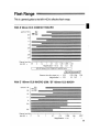
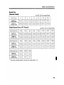
Flash Range
With EF 180mm f/3.5L MACRO USM
ISO
--400
I
x
y-100
C\J
LL
ill
Q5
c
LL
X
""0
:5
~
ill
""0
Q)
ill
L
~
16
c
~ 11
£
~
8
L5 .6
3.5
Aperturet
Distance from film"------.-----.,.------.--------r---------,.
plane (m)
-+ 2
1.2
0.84
0.66
0.57
0.48
Magnification -+ 0.1
0.2
0.3
0.5
0.7
1
With MP-E 65mm f/2.8 1-5x
Aperture t 16
11
8
5.6
4
'l/JJ!]JJJIJJlJiiJllli!J/iffJJffJ!f!!/llW'J/IJII!l!lIIJlI§JJJ;7IJ_I/lII!JIIIJJf!I/.IJ_#I/l'l/fffflll_&
2.8
ISO
--400
100
Distance from film
plane (m)
-+ 0.243
Magnification
18
-+
1
0.238
0.253
0.285
0.313
2
3
4
5
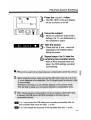
Press the <MODE> button to select the E-TTL (or TTL) autoflash mode or
manual flash mode.
Press the <MODE> button.
~
Pressing the button toggles the flash
mode between ETTL ( TTL) and M
C
Setting the Film Speed
ETTL(TTL)-'M~
._I8III,._1IIIIJIj
The film speed is set automatically according to the film speed set with the camera.
LCD PaneI IIIum ination
&IJJII."IIIJ11I11I!//lI1/I1If1llilllIlllJJ• •lI/11111JJIIIIIIIIIJ_
In low-light, you can illuminate the LCD panel for ( ~12 ).
Press the <=1>:-> button to
illuminate the LCD panel.
~
+
",. © (Q:Q)
©
:8:.( Fn
MODE
SEUSET
L~H"t:I>J
The LCD panel is illuminated for 12
sec.
• To turn off the illumination, press the
<=.c>:-> button again.
• Pressing any button other than the
< PI LOT> and < =J?: > buttons will extend
the illumination time beyond ( ~12 ).
19
I
Focusing Lamp
~111,lIllIJlJl~I[]~lmIUiUllmli~mnlmm~m~
In low-light or when the viewfinder image gets darker at high magnifications, it
becomes difficult to achieve correct focus. In such cases, the focusing lamp
can assist with focusing.
Press the <LAMP>button.
~
The focusing lamps on the top and
bottom of the flash ring will light for
about 20 sec.
PILOT
(Q)O
Focus the sUbject.
Press the < LAM P>button.
• To turn off the focusing lamps, press
the <LAMP> button again.
Resetting to the Default Settings
_JllJlfIJlIJ'• •
When the Macro Ring Lite is attached to an EOS camera equipped with a
<CLEAR> button, pressing the <CLEAR> button resets the Macro Ring Lite's
settings (except the Custom Functions) to its default settings
Press the camera's <CLEAR>
button.
• The default settings are as follows:
~ E-TTL autoflash *
Left and right flash tubes firing at the
same output
Normal flash
* With the EOS-1 Nand EOS-1, TTL autoflash
will be set.
20
When the MR-14EX is mounted on a
Type-A camera such as the EOS-1 V,
taking flash pictures with E-TTL
autoflash is just as easy as normal
autoexposure (AE) pictures.
As with evaluative metering, the E-TTL
autoflash system uses a multi-zone
_ metering sensor which enables highly
precise flash exposure control. A
preflash is fired for evaluative flash
metering and the reading is stored in
memory. The result is a flash picture
with excellent balance between the flash
exposure and ambient light.
For Type-A Cameras
Basic Flash
Photography
o
In macro photography, setting the correct exposure greatly depends on the
subject. It would be best to bracket the exposure even for the same subject.
(~p.32)
[iI·.ThiS s~cti()nusestheEQS-lV as theType-A qamera.
·Sefore proceeding, firsttumonthe MainSwitchonthe EOS~1 V and MR~
14EX.·
.
.
.
• F6rEOS;;t V.<>p~ratiGris,referJo.th~ EOS-1·.Vlnstrl.lctionsbooklet
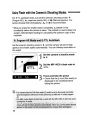
Using Flash with the Camera's Shooting Modes .......
For E-TTL autoflash shots, just set the camera's shooting mode to P
(Program AE), Av (aperture-priority AE), or M (Manual exposure). For
serious closeup flash photography, Av or M is recommended.
* When you press the shutter button completely, a preflash is fired
immediately before the picture is taken. The preflash is used to obtain the
subject's reflected-light reading for calculating the optimum output of the
main flash.
Set the camera's shooting mode to P, and the camera will set the flash
aperture and shutter speed automatically. You can thereby concentrate on
the subject.
Set the camera's shooting mode
to P.
Set the MR-14EX's flash mode to
ETTL.
~
22
60
5.6
•
Focus and take the picture
• Check that the J icon (flash ready) is
displayed in the viewfinder before
taking the picture.
Using Flash with the Camera's Shooting Modes
This mode is effective for controlling the depth of field in your flash pictures.
YC?u can also obtain a correct exposure for both the subject and
background. You set the aperture and the camera sets the shutter speed
automatically for the correct exposure of the background. The E-TTL
autoflash system obtains the correct flash exposure based on the aperture
you set.
Set the camera's shooting mode
to Av and set the aperture.
D
Av
----)
Set the MR-14EX's flash mode to
ETTL.
~
60
5.6
•
Focus and take the picture.
t
• Check that the
icon (flash ready) is
displayed in the viewfinder before
taking the picture.
23
Using Flash with the Camera's Shooting Modes
In this mode, you set both the shutter speed and aperture. The E-TTl
autoflash system controls the flash exposure based on the aperture you
set. The proper exposure of the background is set with both the aperture
and shutter speed.
M
D
Set the camera's shooting mode
to M and set the aperture and
shutter speed.
)
• Set the desired aperture and the
shutter speed anywhere from 30 sec.
to the top sync speed. You can also
use bulb.
Set the MR-14EX's flash mode to
ETTL.
~
24
bO
s.b
•
Focus and take the picture.
• Check that the t icon (flash ready) is
displayed in the viewfinder before
taking the picture.
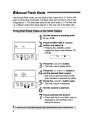
The MR-14EX's advanced features are
explained in this chapter. They are as
follows:
• Selecting the Flash Tube (~p.26)
• Modeling Flash (~p.29)
• FE Lock (~p.30)
• Flash Exposure Compensation
(~p.32)
• FEB (Flash Exposure Bracketing)
(--7p.34)
• High-Speed Sync (FP flash) (~p.36)
• Manual Flash Mode (--7p.38)
• Second-Curtain Synchronization
(~p.40)
For Type-A Cameras
Advanced Flash
Photography
I:iI •This section uses the EOS-1 Vas the Type-A camera:
• Before proceeding, first turn on the Main Switch on the..EOS.. t V and MR14EX.
• For EOS..1Voperati6ns, refer to the EQS:'l Vlnslructions booklet.
~~D
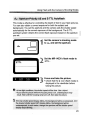
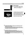
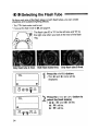
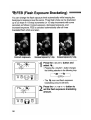
at:Selecting the Flash Tube
IfIItHlni_. nnmllOm'il! i 'I in
By firing only one of the flash tubes or by setting a flash ratio for flash tubes
A and B, you can create shadows and sculptural lighting effects. You can
set the flash ratio from 1:8 to 1:1 to 8:1 (13 levels) in 1/2-stop increments.
* The ETTL flash mode must be set.
* Since the flash exposure is controlled automatically, you need not bother with any
flash metering calculations.
* If you set the flash mode to M, see page 39.
The flash tube ID is "A" for the left one and "B" for
the right one when you look at the rear of the flash
ring.
'
26
A:B=1:1
A:B=4:1
Only flash tube A fired.
Only flash tube B fired.
Selecting the Flash Tube
Press the <RATIO> button and
select IiBml A : B •
ETTL
lim][!] A : B
:~D 8:1- 4:1-
2:1- ~ -1:2 -1:4 -1:8
~
at:
Each time you press the button, the
selection will change in the following
loop:
~(OFF)-~ IiBml A : B I
~IiBmlA:B c~
~
The flash ratio and the
icons will be displayed.
:~D
and
I
at:
Press the < <J > or < C> > button to
move the bar - left or right to set
the respective A:B flash ratio.
• You can set the flash ratio from 1:8 to
1:1 to 8:1
Focus and take the picture.
t
• Check that the
icon (flash ready) is
displayed in the viewfinder before
taking the picture.
27
Selecting the Flash Tube
Follow the same procedure as for "Firing Both Flash Tubes" except for step
2. For step 2, follow the operation below.
ETTL
Press the < <i > or < C> > button to
move the bar - all the way to the
left or right to the ;.D or at: icon.
• ;.D: Fires only flash tube A ~
at:: Fires only flash tube B ~
28
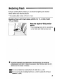
Modelin 9 FIash
....,lIIIJIIjllllllllll.'Jlflllillfllllll.,.JIIIJIIJIIIJIIIIlII.,1/JIJIIlI.1fJ1
Firing a modeling flash enables you to check the lighting and shadow
effects before you take the picture.
* The modeling flash is fired at 70 Hz for 1 sec.
Modeling Flash with Flash Ratio (w/EOS-1 0, 1V, 3, 030, ELAN
7nE, or 30/33)
Press the depth-of-field preview
button.
~ The modeling flash will fire according
to the flash ratio that has been set.
_
C.Fn-6 can disable the modeling flash with flash ratio. (~p.64)
_
C.Fn-4 can have the modeling flash fire at a uniform output with all Type-A
cameras. (~p.64)
29
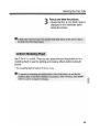
I
With Type-A cameras, you can set FE (flash exposure) lock. This is the
flash version of AE lock. With FE lock, you use spot metering to obtain the
correct flash exposure reading for a specific area of the subject.
* The flash mode must be set to ETTL.
Select a shooting mode with the
camera.
Focus the subject.
Aim the viewfinder's spot
metering circle over the area of
the sUbject to be metered. Then
press the < FEL > button on the
camera. FE lock remains in effect
for 16 sec.
~
~
FEL 5.b
The MR-14EX fires a preflash to
obtain an exposure reading. The
reading is retained temporarily in
memory.
~ FEL is displayed on the viewfinder
bottom for 0.5 sec.
• You can obtain a new FE lock
reading by pressing the < FEL > button
again.
• To cancel FE lock, wait until 16 sec.
elapse or press the <MODE>, <AF>,
or < ~ > button on the camera.
Focus the subject.
30
FE Lock
Take the picture
• In the viewfinder, check the flash
exposure level indicator and check
icon is displayed.
that the
t
~
6 CI
5.6
•
The flash exposure was locked on the
leaf where the butterfly was resting.
After recomposing, the picture was
taken. Since the butterfly's white wings
and the dark background did not affect
the flash exposure reading, the
butterfly was exposed correctly.
With FE lock
. . • If,"th,e" "flas,,h W,ill be, i,n,S",u,
i,ci~nt",
J,WiII,blink,' U, sa, a, la,r,ger aperture (smaller fnumber) and try FE lock again
• FElockcannotb sedwh~n the MR-14~Xis setto the M (Manual) flash
mode. VVith the , ,Elanll/Elan IIE/SO/50E and EOS IX, the t icon blinks in
the viewfinder to warn that FE lock cannot be used.
ft"
31
I
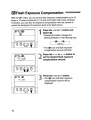
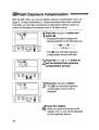
~Flash Exposure Compensation
With the MR-14EX, you can set the flash exposure compensation up to ±3
stops in 1/3-stop increments (or 1/2-stop increments with some cameras).
In tandem, you can also set exposure compensation with the camera to
control the background's exposure level in the flash picture.
Press the < SEUSET > button and
select ~.
~ Pressing the button changes the
blinking selection in the following loop:
~~~~
(OFF)..---J
~
Press the < + > or < - > button to
set the desired flash exposure
compensaJion amount.
ETTI
, \\ -~-,
-+ I 1/3, f I I \ \ '
ETTL
Press the <SEUSET> button.
~
~
+ 11/3
:8~·c Fn
MODE
+
-
"© © (Q;Q)
L~H"~J
32.
The ~ icon and flash exposure
compensation amount will blink.
SEUSET
The ~ icon and flash exposure
compensation amount will be
displayed.
Flash Exposure Compensation
Focus the subject.
~
When you press the shutter button
halfway, the flash exposure
compensation amount will be
displayed on the viewfinder's right
and the ~ icon will be displayed on
the viewfinder bottom.
Take the picture
I
• Check that the ~ and ~ icons are
displayed in the viewfinder before
taking the picture.
~
:;0
5.:;~
•
Ill. Flash exposure compensation set ,with the MR-14EX overrides any flash
exposure~ompensationsetwith the camera.
- In step 3, instead of pressingt~e<SEUSET > qutton,you can press the shutter
button hal~ay ~Q;§ett~eiflash~xpos~reco~pensation. '
-Ifyou take a picture during step 2 (while the flash exposure compensation
a,,!TI,ee" ~n,t, Is's,til,I bl,ink,;ing"), th,e"na,s,',eh, e,xp,e,SU, r,e cern",pensatiQn will ta,k,e e,,ffe,ct in, the
pi6ture according to the blinking amount.,
'
,
-If the'subJec(issmaJl, and the background is dark or, faraway, flash exposure
comp,ensation may not obtain the desired result. 'In such a case, use the
manual flash mode. (--tp.38)
33
~ FEB
(Flash Exposure Bracketing) fI.~mnnlnil.1I111
You can change the flash exposure level automatically while keeping the
background exposure level the same. Three flash shots can be bracketed
up to ±3 stops in 1/3-stop increments (or 1/2-stop increments with some
cameras) as follows: Correct exposure, decreased exposure, and
increased exposure. FEB is canceled automatically after all three
bracketed flash shots are taken.
Correct exposure.
-~
n/
-' u
- /1'
ETTLI
/1'
Decreased exposure by 1stop.
Increased exposure by 1stop.
Press the < SEUSET > button and
select ~.
~
Pressing the < SEUSET > button
changes the blinking selection in the
following loop:
~---+~~
(OFF)~
~
ETTL, 1 /~
-2/3 I '
/1'
34
The ~ icon and flash exposure
bracketing amount will blink.
Press the <+> or <-> button to
set the flash exposure bracketing
amount.
FEB (Flash Exposure Bracketing)
Press the < SEUSET > button.
ETTL
~
D
Fb
The MR-14EX's LCD panel display
will be as shown on the left.
- I
Focus the subject
:.8.:·C.Fn
'©
MODE
+
-
© (Q;:Q)
L~H"~J
SEUSET
~
When you press the shutter button
halfway, the FEB setting is displayed
on the viewfinder's right.
Take the picture.
t
• Check that the
icon is displayed in
the viewfinder before taking the picture.
~
::. c:
5.:;
•
Repeat steps 4 to 5 to take the
remaini"ng two bracketed shots.
• After all three bracketed shots are
taken, the FEB setting is cancelled
automatically.
O···FEI3:·.(}an.n.otbe·.··.es~d·····.witt1··.··.ar1¥··fla.sn.··• ·exposu·re.·(}ompensation.·.··set•.·w.itb.tne·.·.carnera.
[ll-.Before
takil"l~ tbepicture! make seretbat tbe MR~14E
i:r~~::m~~~:J.eaitl the viewtiader. The . ..
-In tne ~, ~L,~H, or~H« continuous shooti
ith tbeEOS-1D, 1V
orEQS;,3, the next braG~etedpicture"
. not ready.
Wbilethe flash is not ready, yoecan
alAE mode
ifyburelease yo~rfiriger
etely.
.....
.,'
'. EOS-3, iftbe flash is not
-Witb.Type-A cameras ot '.
ready, yoe can stiUtake picteres.ih·thE1 normal AE.m()de.
- When the flasb is ready, you can reseme taking the bracketed flash shots.
~~ -FE lock and FEB can, be ul?edJn ~of'l'ibiflation.
- FEB and flash exposure compensation canbe settogether \Nith the MR-14EX. In this
case, the FEB amountwill shift accordingtothe.flashexposure compensation amount.
_
C.Fn-1 can prevent the FEB setting from canceling aetomatically after tbe
three bracketed flash sbots are taken. (~p.64)
_
C.Fn-2 can change the sequence of the bracketed flash shots. (~p.64)
35
I
eDHigh-Speed Sync (FP Flash)
IIIIIlIiJ
I . _ t i l l. .
With high-speed sync (FP flash), the MR-14EX can synchronize with the
camera at all shutter speeds even those faster than the normal sync speed.
When high-speed sync is set, ~ is displayed in -the viewfinder.
* High-speed sync can be used in the ETTL and M flash modes.
* High-speed sync is especially effective for fill-flash in daylight, enabling you to:
(1) Obtain better background blur with a larger aperture.
(2) Soften shadows.
With normal flash.
With FP flash.
Select the camera's shooting
mode and the MR-14EX's flash
mode.
Press the <+> and <-> buttons
simultaneously to select GD.
~
Each time you press the < + > and
< - > buttons simultaneously, the
setting changes in the following loop.
~eD~~~
~(OFF)4
36
~
High-Speed Sync (FP Flash)
~H
:000 2.8
•
Focus and take the picture.
• Check that the ~ icon is displayed in
the viewfinder before taking the
picture.
I
37
In the manual flash mode, you can set the flash output from 1/1 (full) to 1/64
power in whole-stop increments. The flash tubes can be fired in one of three
configurations: 1. Fire both flash tubes at the same output, 2. Fire flash tube
A at a different output from flash tube B, 3. Fire only one of the flash tubes.
Set the camera's shooting mode
to Av or M.
Press the MR-14EX's <MODE>
button and select M.
~
Pressing the <MODE> button
toggles the flash mode between
ETTL and M.
C
ETTL ---+ M~
Press the < SEUSET > button.
~
The flash output display blinks.
Press the < + > or <- > button to
set the desired flash output.
~
Each time you press the button, the flash
output increases or decreases by one stop.
Press the < SEUSET > button again.
~ The flash output is displayed.
Set the camera's aperture.
Focus and take the picture.
• Check that the J icon (flash ready) is
displayed in the viewfinder before
taking the picture.
38
Manual Flash Mode
Firi'ngBothFlashTtllbe~$t
aD,ifferentOutput
For step 3 on the preceding page, following the procedure below to set a
different flash output between flash tube A and B
M
IiJ.iDI!) A : B
Press the <RATIO> button and
select IiBml A : B •
~
~tD
M
Each time you press the button, the
selection will change in the following loop:
IiBml A : B I
~IiBmlA:B:C~
r--+(OFF)-~
• The flash output is displayed on the
lower right of the LCD panel. When
A is displayed, the flash output
displayed is for flash tube A.
Press the < <J > or < C> > button to
select flash tube A or B, then
press the < + > or <- > button to
set the flash output.
~
First select the flash tube, then set the
flash output for that flash tube.
• The remaining steps are the same as
steps 6 and 7 on the preceding page.
Firing Only One Flash Tube
Press the <-> button and set the flash output to --. This disables the
selected flash tube from firing.
• The -- setting comes after the 1/64 setting. The flash tube whose flash
output is set to -- will not fire. Also, you cannot set -- for both flash tubes.
39
I
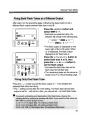
t:t> Second-Curtain Synchronization
.,IiIIIIIIJBIfIIJ
Normally, the flash fires in synchronization with the first shutter curtain when
the shutter is fully open. With second-curtain synchronization, the flash fires
immediately before the second shutter curtain closes at the end of the
exposure.
Set the shooting mode with the
camera.
Press the < + > and <- > buttons
simultaneously to select [:I> on
the LCD panel.
~ Each time you press the < + > and
<-> buttons simultaneously, the
synchronization mode changes in the
following loop:
~
GD
---+ [:I> ~
~ (OFF).----l
Focus and take the picture.
~
40
Check that the J icon is displayed in
the viewfinder before taking the
picture.
This chapter explains the MR-14EX's
built-in features for wireless flash
photography with one or more additional
Speedlites.
• Setting Up a Wireless Flash System
(~p.42 )
• Using the Wireless Flash System
(~p.45)
For Type-A Cameras
Wireless Flash
Photography
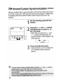
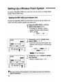
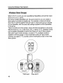
Setting Up a Wireless Flash System
""1II!JI1IIIIIfJIIII.
By using a Speedlite 550EX as a slave unit, you can set up a wireless flash
system with the MR-14EX.
As with the Speedlite 550EX, the MR-14EX can be set as the master unit
which transmits wireless signals to the slave unit.
Press the MR-14EX's <MODE>
button and select ETTL.
~
Pressing the < MODE> button
toggles the flash mode between
ETTL and M.
CETTL-'M~
Press the <RATIO> button and
select CBml A : Be.
ETTL
IifMI!] A : B
~.D 8:1- 4:1-
C
+0
2:1 - ~ -1:2 -1:4 -1:8
~
at:
Each time you press the button, the
selection will change in the following
loop:
~(OFF)-~
~ CBml
~
IifMI!] A : B
42
B~
c.---J
I&:. will be displayed.
Press the <CH.> button to select
the channel.
ETTL
~.D 8:1-
CBml A:
A: B
C
+0
4:1- 2:1- ~ -1:2 -1:4 -1:8
• Select a channel from 1 to 4.
at:
Setting Up a Wireless Flash System
To set the 550EX as a slave unit, refer to page 53 in the 550EX's
Instructions booklet.
ETTL
mZoom
Set the same channel No. as the
master unit.
2lfmm
c
Set the slave 10 to C.
After setting up the wireless flash
system, position slave C as
shown in the left diagram.
• When indoors, position the slave unit
within 5 meters from the master unit.
When outdoors, position it within 3
meters. The slave unit should also be
within an aD-degree angle in front of
the master unit.
• Face the slave unit's transmission
sensor toward the master unit.
• Indoors, the transmission signals can
bounce off the walls so the slave unit's
positioning can be a little more flexible.
• Do not place any objects between the
master unit and slave unit which may
obstruct the wireless transmission.
Check that the master unit's pilot
lamp is lit and that slave C is
flash-ready.
~
When the slave unit is flash-ready, its
AF-assist light will blink.
43
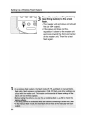
Setting Up a Wireless Flash System
Press the master unit's pilot lamp
(test firing button) to fire a test
flash.
~
The master unit and slave unit should
fire (at 1/64 output).
• If the slave unit does not fire,
reposition it closer to the master unit
and more toward the front and center
of the master unit. Then fire a test
flash again.
44
Using the Wireless Flash System
rJIIIIIJm nu ~I~~
Using Slave C (w/EOS-10, 1V, 3, 030, ELAN 7nE, or 30/33)
You can fire flash tubes A and B and slave C at the same time. A correct
flash exposure is obtained with flash tubes A and B together, and slave C
alone is set automatically to obtain a correct exposure. Slave C is used to
eli"minate background shadows or to create accent lighting.
Check that Imiml A : B C is
displayed on the LCD panel_
Imiml
A : B
:~D 8:1- 4:1-
C
+0
2:1- ~ -1:2 -1:4 -1:8
• If it is not displayed, press the < RAT I0 >
button until it is displayed. (-7p.42)
at:
Check that the master unit's pilot .
lamp is lit and that slave C is also
flash-ready.
Focus and take the picture.
Check that the master unit's flash
exposure confirmation lamp lights.
_
With Type-A cameras, C. Fn-5 can have both the master unit and slave unit
fire together as one group. (~p.64)
• While Imiml is not displayed on the master unit, you can just position the
slave unit as desired.
.
45
Using the Wireless Flash System
You can also set a flash ratio for flash tubes A and 8 and set flash exposure
compensation for slave C. After step 1 on the preceding page, follow the
procedure below.
--
ETTL
1
Imm!l
+0
A : B C
:~D 8:1· ~. 2:1·1:1 ·1:2 ·1:4 ·1:8 at:
Press the < <J > or < C> > button to
set a flash ratio for flash tubes A
and B.
• To set the flash ratio for flash tubes A
and 8, see page 27.
• The sample diagram on the left
shows the left: right flash ratio set to
4:1.
• When emml is displayed, you can
change the flash ratio anytime.
ETTL
+
-1
A : B C
I 1/3
:~D8:1.~. 2:1·1:1·1:2 .1:4.1:8at:
Imm!l
46
Press the < + > or <- > button to
set slave C's flash exposure
compensation amount.
• The amount can be set up to ±3
stops in 1/3- or 1/2-stop increments.
• The remaining steps are the same as
steps 2 and 4 on page 45.
Using the Wireless Flash System
Features Available with, Wireless Flash
The following features can also be used in a wireless flash system:
•
•
•
•
Wireless
Wireless
Wireless
Wireless
FE Lock
flash exposure compensation
flash exposure bracketing (FEB)
high-speed sync (FP flash)
Wireless Manual Flash
With all Type-A cameras, you can also set up a wireless manual flash
system.
Setting the flash output for flash tubes A and 8 and slave C
With Iimml A : B : C displayed on the master unit, set the flash output for
flash tubes A and B. Then set the flash output for slave C. For the setting
procedure, see "Firing Both Flash Tubes at a Different Output" on page 39.
Cil
To determine the correct flash exposure, use a hand-held flash meter or take
test shots.
_ _ With all Type-A cameras, C.Fn-5 can set the same flash output for flash
tubes A and B and slave C. (~p.64)
• While Iil:.1iI!] is not displayed on the master unit, you can just set the flash
output with the master unit.
47
Using the Wireless Flash System
When C.Fn-5-1 is set, you can use additional Speedlites and set their slave
IDs t9 A, B, or C.(~p.64)
By having multiple Speedlites set to the same slave 10, you can create a
slave group to produce a brighter flash. For example, a slave unit whose
slave 10 is A will fire together with flash tube A. Each slave group is treated
as one Speedlite, with the same flash settings applied to all the Speedlites
in the group.
There is no limit as to the number of slave units that can belong to one group.
With the EOS-1 0, 1V, 3, 030, ELAN 7/7E, or 30/33, E-TTL autoflash control
can be applied individually to each of the three A, B, and C slave groups.
With other Type-A EOS cameras, the same E-TTL autoflash control is
applied to all three groups. In the manual flash mode, all Type-A EOS
cameras can apply E-TTL autoflash control individually to each of the three
slave groups.
Slave C Slave C
ii
Group C
Flash tube B
48
Flash tube A
When the MR-14EX is mounted on a
Type-B camera such as the EOS-1 N,
taking flash pictures with TTL autoflash
is just as easy as normal autoexposure
(AE) pictures. In the Full Auto mode, you
can just press the shutter button to take
flash pictures. Or you can set the shutter
speed or aperture while the flash
exposure is automatic. In this way, you
can take various flash pictures.
With the EOS-1 N, the flash exposure is
controlled with the 3-zone, TTL
autoflash system (real-time off-the,;.film
flash metering).
For Type-B Cameras
Basic Flash
Photography
Using Flash with the Camera's Shooting Modes
rJllIJIJIIJllWmrnnr.-
For TTL autoflash shots, just set the camera's shooting mode to P
(Program AE), Av (aperture-priority AE), or M (Manual exposure). For
serious closeup flash photography, Av or M is recommended.
* When you press the shutter button completely, TIL autoflash metering
(the light reflected off the film is metered and the flash is cut off when the
proper amount of light is received) is used to control the flash exposure
based on the flash aperture.
Set the camera's shooting mode to P, and the camera will set the flash
aperture and shutter speed automatically. You can thereby concentrate on
the subject.
Set the camera's shooting mode
to P.
p
Set the MR-14EX's flash mode to
TTL.
60
50
5.6
~
•
Focus and take the picture.
t
• Check that the
icon (flash ready) is
displayed in the viewfinder before
taking the picture.
Using Flash with the Camera's Shooting Modes
This mode is effective for controlling the depth of field in your flash pictures.
You can also obtain a correct exposure for both the subject and
background. You set the aperture and the camera sets the shutter speed
automatically for the correct exposure of the background. The TIL
autoflash system obtains the correct flash exposure based on the aperture
you set.
Av
I
D
Set the camera's shooting mode
to Av and set the aperture.
I
Set the MR-14EX's flash mode to
TTL.
60
5.6
~
•
I
Focus and take the picture.
t
• Check that the
icon (flash ready) is
displayed in the viewfinder before
taking the picture.
51
Using Flash with the Camera's Shooting Modes
In this mode, you set both the shutter speed and aperture. The TTL
autoflash system controls the flash exposure based on the aperture you
set. The proper exposure of the background is set with both the aperture
and shutter speed.
M
I
DI
Set the camera's shooting mode
to M and set the aperture and
shutter speed.
• Set the desired aperture and the
shutter speed anywhere from 30 sec.
to the top sync speed. You·can also
use bulb.
Set theMR-14EX's flash mode to
TTL.
6Q
52'
5.6
~
•
Focus and take the picture.
• .Check that the J icon (flash ready) is
displayed in the viewfinder before
taking the picture.
The MR-14EX's advanced features are
explained in this chapter. They are as
follows:
• Selecting the. Flash Tube (~p.54)
• Flash Exposure Compensation
(~p.56)
• FEB (Flash Exposure Bracketing)
(~p.58)
• Manual Flash Mode (~p.60)
• Second-Curtain Synchronization
(--7p.62)
• Wireless Manual Flash (~p.63)
For Type-B Cameras
Advanced Flash
Photography
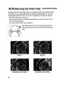
~~D O~;Selecting
the Flash Tube
I~.
liWIUUflIIEHUJj[.
By firing only one of the flash tubes or both flash tubes, you can create
shadows and sculptural lighting effects.
* The TTL flash mode must be set.
* If you set the flash mode to M, see page 61 .
The flash tube 10 is "A" for the left one and "B" for
the right one when you look at the rear of the flash
ring.
Only flash tube A fired.
80th flash tubes fired.
Only flash tube 8 fired.
Press the <RATIO>button.
~
The ~.D and
displayed.
at:
icons will be
Press the < <l > or < C> > button to
select the flash tube(s).
• ~.D at::
~ and ~ will fire.
~.D: ~ will fire.
at:: ~ will fire.
54
Selecting the Flash Tube
Focus and take the picture.
t
• Check that the
icon (flash ready) is
displayed in the viewfinder before
taking the picture.
Set C.Fn-4-1 (.-7p.64). Then you can press the test firing button to fire a
modeling flash to see the lighting and shadow effects before taking the
picture.
* The modeling flash is fired at 70 Hz for 1 sec.
55
~ Flash
Exposure Compensation
nlinl
til, J r L nil
With the MR-14EX~ you can set the flash exposure compensation up to ±3
stops in 1/3-stop increments (or 1/2-stop increments with some cameras).
"In tandem, you can also set exposure compensation with the camera to
control the background's exposure level in the flash picture.
Press the <SEUSET> button and
select ~.
TTL-~
'A
u -I '
~
, I '
:~.~·C.Fn
'(9)
MODE
©
+
-
(Q:Q)
~~----+~
~(OFF)~
SEUSET
L~H"~J
Pressing the button changes the
blinking selection in the following loop:
~
The ~ icon and flash exposure
compensation amount will blink.
Press the < + > or < - > button to
set the desired flash exposure
compensation amount.
TTL
+I
:.8.~·C.Fn
'(9)
Press the <SEUSET> button.
~
~
1/3
MODE
+
-
© (Q:Q)
The ~ icon and flash exposure
compensation amount will be
displayed.
SEUSET
L~H"~J
Focus the SUbject.
~
56
When you press the shutter button
halfway, the ~ icon will be displayed
on the viewfinder bottom.
Flash Exposure Compensation
Take the picture.
• Check that the t and ~ icons are
displayed in the viewfinder before
taking the picture.
50
5.5
~ ~
•
57
~ FEB (Flash Exposure Bracketing)
You can change the flash exposure level automatically while keeping the
background exposure level the same. Three flash shots can be bracketed
up to ±3 stops in 1/3-stop increments (or 1/2-stop increments with some
cameras) as follows: Correct exposure, decreased exposure, and
increased exposure. FEB is canceled automatically after all three
bracketed flash shots are taken.
Correct exposure.
Decreased exposure by 1stop.
Increased exposure by 1stop.
Press the <SEUSET> button and
select ~.
~
:8:·, Fn
"@
MODE
+
-
© CQ::Q)
L~H"~J
TTL, I /~
-~/3 I '
/1'
58
Pressing the < SEUSET > button changes
the blinking selection in the following loop:
~~--+~~
L--(OFF)4 ~
SEUSET
~
The ~ icon and flash exposure
bracketing amount will blink.
Press the < + > or <- > button to
set the flash exposure bracketing
amount.
FEB (Flash Exposure Bracketing)
Press the < SEUSET > button.
TTL
~
o
The MR-14EX's LCD panel display
will be as shown on the left
Fb - I
~~:·C.Fn
©
MODE
+
-
© (Q:Q)
SEUSET
Focus the subject.
L~H"~J
~
6a
5.6
~ ~
•
When you press the shutter button
halfway, the ~ icon is displayed on
the viewfinder's bottom.
Take the picture.
t
• Check that the
and ~ icons are
displayed in the viewfinder before
taking the picture.
Repeat steps 4 to 5 to take the
remaining two bracketed shots.
• After all three bracketed shots are
taken, the FEB setting is cancelled
automatically.
_
C.Fn-1 can prevent the FEB setting from canceling automatically after the
three bracketed flash shots are taken. (-7p.64)
_
C.Fn-2 can change the sequence of the bracketed flash shots. (-7p.64)
59
In the manual flash mode, you can set the flash output from 1/1 (full) to 1/64
power in whole-stop increments. The flash tubes can be fired in one of three
configurations: 1. Fire both flash tubes at the same output, 2. Fire flash tube
A at a different output from flash tube 8,3. Fire only one of the flash tubes.
Set the camera's shooting mode
to Av or M.
Press the MR-14EX's <MODE>
button and select M.
~ Pressing the <MODE> button
toggles the flash mode between TTL
and M.
CTTL~M~
Press the
~
<SEUSET>
button.
The flash output display blinks.
Press the < + > or <- > button to
set the desired flash output.
~
Each time you press the button, the flash
output increases or decreases by one stop.
Press the < SEUSET > button again.
~ The flash output is displayed.
Set the camera's aperture.
Focus and take the picture.
• Check that the t icon (flash ready) is
displayed in the viewfinder before
taking the picture.
60
Manual Flash Mode
After step 3 on the preceding page, following the steps below to set a
different flash output between flash tube A and B.
M
Press the <RATIO> button and
select IimiI!l A : B •
~
Each time you press the button, the
selection will change in the following loop:
A: B I
~IimiI!lA:B:C~
~(OFF)-~1imiI!l
• The flash output is displayed on the
lower right of the LCD panel. When
A is displayed, the flash output
displayed is for flash tube A.
M
fiBiI!) A : B
~.D
Press the < <J > or < C> > button to
select flash tube A or B, then
press the < + > or < - > button to
set the flash output.
~
First select the flash tube, then set the
flash output for that flash tube.
• The remaining steps are the same as
steps 6 and 7 on the preceding page.
Press the <-> button and set the flash output to --. This disables the
selected flash tube from firing.
• The -- setting comes after the 1/64 setting. The flash tube whose flash
output is set to -- will not fire. Also, you cannot set -- for both flash tubes.
61
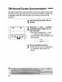
t:l>Second-Curtain Synchronization
Normally, the flash fires in synchronization with the first shutter curtain when
the shutter is fully open. With second-curtain synchronization, the flash fires
immediately before the second shutter curtain closes at the end of the
exposure.
Set the shooting mode with the
camera.
Press the < + > and < - > buttons
simultaneously to select t::I> on
the LCD panel.
~ Each time you press the < + > and
<-> buttons simultaneously, the
synchronization mode changes in the
following loop:
C==;~F):=J
Focus and take the picture.
~
62
Check that the t icon is displayed in
the viewfinder before taking the
picture.
Wireless Manual Flash
.~lj.I~•••
III.I~.I~i.I~I.I~".H.·~~~~•••••
~ ---
With all Type-B cameras, you can also set up a wireless manual flash
system.
* To set up a wireless flash system, follow the same procedure for Type-A cameras
on page 42 to 44.
* W"ireless autoflash is not possible.
Setting the flash output for flash tubes A and 8 and slave C
With IimiM A : B : C displayed on the master unit, set the flash output for flash
tubes A and B. Then set the flash output for slave C. For the setting
procedure, see "Firing Both Flash Tubes at a Different Output" on page 61.
_ _ With all Type-B cameras, C.Fn-5 can set the same flash output for flash
tubes A and B and slave C. (~p.64)
• While IimiM is not displayed on the. master unit, you can just set the flash
output with the master unit.
When C.Fn-5-1 is set, you can use
additional Speedlites and set their slave
IDs to A, B, or C. (~p.65)
By having multiple Speedlites set to the
same slave ID, you can create a slave
group to produce a brighter flash. For
example, a slave unit whose slave ID is
A will fire together with flash tube A.
Each slave group is treated as one
Speedlite, with the same flash settings
applied to all the Speedlites in the group.
There is no limit as to the number of
slave units that can belong to one group.
Group C
Flash tube B
Flash tube A
63
en Custom Functions
rJlJ,UIJJlJlmrlmrJllrllfljl!~.I'.I.II.~. . . .".11rim_I1.11.1~.I~lIJJJIJrJIIIJ.
Custom Functions enable you to customize the MR-14EX's functions
according to your preferences.
Press the <C.Fn> button for at
least 2 sec.
~
The C6 icon, Custom Function No.,
and setting No. will appear on the
LCD panel.
Press the < SEUSET > button.
~
The Custom Function No. and setting
No. will start blinking.
~ Each time you press the button, the
next Custom Function No. will appear
from F1 to F7.
Press the <+> or <-> button to
set the Custom Function setting.
~
Set it to 0 or 1 according to your
preference.
Press the <SEUSET> button.
~
The display stops blinking, and the
Custom Function is set.
Press the <C.Fn> button or the
<MODE> button
~
The MR-14EX is now ready for
picture-taking.
• You need not press the <C.Fn>
button for 2 sec. or longer.
64
IN?
Pi
57
1_7 P
Custom Functions
IIIII[ iiI. . . ;;TTlllrrn:mli.~Rllf.JP;; 7F
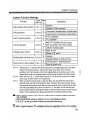
Custom Function Settings
Function
Custom Setting
Function No, No
FEB cancellation after completion C.Fn-1
FEB sequence
C.Fn~2
Flash metering system
C.Fn-3
Test firing button
C.Fn-4
Wireless slave control
Modeling flash with flash ratio
C.Fn-5
C.Fn-6
Power source for flash charging C.Fn-7
0
Description
Enabled
1
Disabled (FEB continues)
0
Correct exposure, decreased exposure, increased exposure
1
decreased exposure, correct exposure, increased exposure
0
E-TTL autoflash
1
TTL autoflash
0
With E-TIL autoflash, fire at full output
With manual flash, fire at the set output
1
Uniform modeling flash
0
Slave Conly
1
Slaves A, B, and C
0
Enabled
Disabled (Depth-of-field preview)
1
0
1
Internal power + External power
External power only
C.Fn-4: Setting this to "1" will have the flash heads fire the modeling flash fire at the same
output with all EOS cameras. If both flash heads have been set to fire with
autoflash, both flash heads will fire the modeling flash at the same output. In the
manual flash mode, the modeling flash will be fired at the flash ratio set manually.
C.Fn-5: When this is set to "1", slave units whose 10 is A or B will fire as part of the same
slave group as flash tube A or B respectively.
C.Fn-7: When an external power pack is used, the flash unit uses both the internal and
external power sources to recharge the flash. However, the internal power source
may become exhausted sooner than the external power pack, preventing the flash
from firing. By setting this Custom Function to "1," the flash unit will use only the
external power pack to recharge the flash so that the internal power source will last
longer. (The focusing lamp is always powered by the internal power source.)
O· With a Type-A cartlera, theC.Fn-3-1' setting wiUnQt enable wireless operation
with autoflash.
.
• With the E()§D30carnera, settingy.Fn-:3-1 will' disable the flash.
-If, C. Fn-5-1 i~ set, you cannot have only oneflashtljbefiring.
!11."\fllitha-ryp~"~:c;8J'ne(8,J7J"I.;.~lJt9fl~Sh·wil!;b~·.$~t·
• regargle$~ofth.~·.'C;Fn-3.',settinQ.
65
MR-14EXlMT-24EX System
nUl
nmn
I
~jl.n.lj.IIUil~i~11111
. . -.- 1
CD
§@
§
§
§
~
@
o
0
@
~"""""""~
I
®
@
@
8-0-Q,
@
£!DDlIn-'1111111111111111111111~
@
O-------IIIl\)
,-C
66
aQJJIDJ
The accessories on the left enable
wired, multi-Speedlite TIL autoflash.
@ TTL Hot Shoe Adapter 3
®
TTL Distributor
@ Off-Camera Shoe Adapter OA-2
@ Connecting Cord 60
@ Connecting Cord 300
MR-14EXlMT-24EX System
III
1111111111III. I
I
lRii
1_
CD
Macro Ring Lite MR-14EX
Macro Twin Lite MT-24EX
@ Connecting Cord ET (included with Transistor Pack E)
@ Transistor Pack E
®
Houses Battery Magazine TP or Ni-Cd Pack TP.
@ Battery Magazine TP
Houses six size-C alkaline batteries.
®
Ni-Cd Pack TP
Ni-Cd pack dedicated to Transistor Pack E.
Shortens flash recycle time as with a high-voltage battery. Rechargeable with NiCd Charger TP for repeated use.
(j) Ni-Cd Charger TP
Dedicated charger for Ni-Cd Pack TP. Charging time is about 15 hours.
®
Compact Battery Pack CP-E2
Small and lightweight external power source. It uses six size-AA alkaline or
nickel-hydride batteries. It can also use lithium batteries.
®
Speedlite 550EX (Slave unit)
@) Speedlite 420EX (Slave unit)
®
Mini Stand (provided with the 550EX and 420EX)
Mini stand to prop up the 550EX or 420EX positioned as a remote slave unit.
Tripod socket provided at the bottom.
@ Off-Camera Shoe Cord 2
For off-camera flash operation up to 60 em away from the camera. All flash
functions can be used. (Not compatible with the EOS 630/600 and RT.)
67
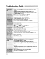
Troubleshooting Guide
II
The MR-14EX's mounting foot is not securely mounted on the camera's
hot shoe.
~ Slide the mounting foot all the way into the hot shoe.(~p.13)
The camera's hot shoe contacts or the MR-14EX's contacts are soiled.
~ Clean the contacts. (~p.13)
Batteries have not been installed in the MR-14EX.
~ Install batteries in the MR-14EX. (~p.10)
The batteries in the MR-14EX are exhausted.
~ Install new batteries in the MR-14EX. (~p.1 0)
Flash exposure compensation has been set.
~ Cancel the flash exposure compensation.
(~p.32,
56)
C.Fn-5-1 has been set.
, ~Set C.Fn-5-0. (~p.64)
IiBiI!l A : B C (1iBiI!l A : B : C ) has been set
~
Set to IiBmJ
A: B. (~27,
39, 61)
The main switch is set to SE.
~ Set the main switch to ON.
~ Press the test firing button.
(~p.15)
(~p.16)
The locking collar has not been loosened enough.
• Loosen the locking collar until the locking pin disengages.(~p.13)
"C.Fn-3-1 has been set.
~ Set C.Fn-3-0. (~p.64)
The slave unit's wireless selector is set to OFF or MASTER.
~ Set the wireless selector to SLAVE.
(~p.16 of 550EX Instructions/~p.13 of 420EX Instructions)
The slave unit is not within the master unit's wireless transmission range.
~ Position the slave unit within the master unit's wireless transmission range.
(-7p.43, 63)
The slave unit's transmission sensor is not facing toward the master unit.
~ Face the slave unit's transmission sensor toward the master ~nit.
(~p.43, 63)
Slave C is pointed directly 'at the front of the subject.
~ Use slave C in another way. (~p.43)
68
Specifications
Type
Closeup photography-dedicated, ring-type flash with two flash tubes,
wireless transmissionlreception functions, and E-TTUTTL autoflash control
Compatible cameras
Type-A EOS cameras (for E-TTL autoflash control)
Type-B EOS cameras (for TTL autoflash control)
Compatible lenses
EF 50mm f/2.5 COMPACT MACRO, EF 100mm f/2.8 MACRO USM, EF
1OOmm f/2.8 MACRO, EF 180mm f/3.5L MACRO USM, and MP-E 65mm
f/2.81-5x
Flash coverage
80 deg. vertical, 80 deg. horizontal
Guide NO
(-7p.71)
Flash count and recycling time
(-7 p.11, 12)
Flash modes
(1) E-TTL autoflash (w/Type-A cameras)
• FE lock, flash exposure compensation, FEB, flash ratio control
(2) TTL autoflash (w/Type-B cameras)
• Flash exposure compensation, FEB
(3) Manual flash (w/Type-A/B cameras)
• 111 - 1/64, whole-stop increments, 7 steps
Firing mode
(1) Normal flash
(2) High-speed sync (FP flash)
(3) Test flash
(4) Modeling flash
• With C.Fn-6-0: Modeling flash with flash ratio (w/EOS-1 D, 1V, 3, D30,
ELAN 717E, or 30/33)
• With C.Fn-4-1: Uniform modeling flash (w/all EOS cameras)
(5) Preflash
Flash tube firing mode
(1) Both flash tubes firing
• Both flash tubes fired at the same output (E-TTUTTL autoflash)
• Both flash tubes fired according to a flash ratio (E-TTL autoflash)
• Both flash tubes fired manually (Manual flash)
(2) Only one flash tube firing (All flash modes)
Only flash tube A or B fired
High-speed sync
Enabled in E-TTL autoflash and manual flash modes
Flash exposure compensation (1) Automatic compensation: Automatic flash output reduction for fill flash.
(2) Manual adjustment of flash exposure compensation withe MR-14EX: Up
to ±3 stops in 1/3- or 1/2-stop increments
(3) Manual adjustment of flash exposure compensation withe camera: Up
to ±3 or ±2 stops in 1/3- or 1/2-stop increments
FEB
Adjustable with the MR-14EX: Up to ±3 stops in 1/3- or 1/2-stop increments
Flash tube A: B ratio control 1:8 - 1:1 - 8: 1, 1/2-stop increments, 13 steps
Shutter curtain sync
1st- or 2nd-curtain sync enabled
Flash-ready indicator
Red pilot lamp
Flash range (at f/2.8, ISO 100) (1) Normal flash: Approx. 20mm - 5 m/0.8 in - 16 ft
(2) Hgh-speed sync (FP flash) at 1/320 sec.: Approx. 20mm - 2.2 m/0.8 in -7.2 ft
Flash exposure confirmation ......Pilot lamp lights in yellow-green (for 3 sec.) immediately after the picture is
taken.
Sync speed
(-7 p.72)
Flash duration
(1) Normal flash: 1.4 ms or less
(2) High-speed sync (FP flash): 26 ms or shorter.
69
Specifications
Color temperature
Focusing lamps
Wireless Functions
Transmission system
Configuration
Firing control
Slave groups
Flash modes
Approx. 5500 K (Equivalent to daylight)
Coverage: 40 deg. vertical, 45 deg. horizontal
Light duration:Approx. 20 sec.
Optical pulse transmission
EOS camera, MR-14EX, and 550EX (slave)
Slaves centrally controlled by MR-14EX master unit
[E-TTL autoflash]
With EOS-1D, 1V, 3, D30, ELAN 7nE, and 30/33:Max. 3 groups (A, S, C)
With other Type-A cameras:1 group (no ID)
[Manual Flash]
Max. 3 groups (A, B, C) with both Type-A and B cameras
(1) E-TTL autoflash (wlType-A cameras)
(2) Manual autoflash (wlType-A/B cameras)
1 to 4
Same as flash coverage
Channels
Transmission angle
Transmission range (w/slave
facing the master straight on) ....Indoors: Approx. 20 cm - 5 m/0.65 ft - 16.4 ft
Outdoors:Approx. 20 cm - 3 m/0.65 ft - 9.8 ft
Film speed
Set automatically according to the camera's setting (ISO 6 - 6400)
Custom Functions
(--7p.64)
Main switch
3 positions:OFF, ON, SE (turns off after 90 sec. of idle)
Power source
[Internal power sources] (--7p.11)
(1) Size-AA alkaline batteries x 4
(2) Size-AA nickel-hydride batteries x 4
• Size-AA lithium batteries x 4 also can be used.
[External power sources] (--7 p.12, 66)
(1) Compact Battery Pack CP-E2
(2) Transistor Pack E
Dimensions
Control unit:74.0 (W) x 125.9 (H) x 97.4 (D) mm
2.9 (W) x 5.0 (H) x 3.8 (D) in
Flash ring:112.8 (W) x 126 (H) x 25.6 (D) mm
4.4 (W) x 5.0 (H) x 1.0 (D) in
Cord length:Approx. 25 cm/9.8in
Weight
.430g/15.1 oz (excluding batteries)
• Specifications are based on Canon's testing criteria.
• Specifications and the product exterior are subject to change without notice.
70
Specifications
Guide No.
[Normal Flash]
Flash Output
Guide No.
(At ISO 100 in meters/feet)
1/1
1/4
1/8
1/16
1/32
1/64
7.0/23.1
5.0/16.5
3.5/11.5
2.5/8.2
1.8/5.9
1/2
14.0/46.2 10.0/33
[High-Speed Sync (FP Flash)]
(At ISO 100 in meters/feet)
Shutter Speed (sec.)
1/125
1/160
1/200
1/250
1/320
1/400
1/500
1/640
Guide No.
7.9/26
7.6/25
7.2/23.7
6.8/22.4
6.2/20
5.5/18.1
4.9/16.1
4.4/14.5
Shutter Speed (sec.)
1/800
1/1000
1/1250
1/1600
1/2000
1/2500
1/3200
1/4000
Guide No.
3.9/12.8
3.5/11.5
3.1/10.2
2.7/8.9
2.4/7.9
2.217.2
1.9/6.2
1.7/5.6
Shutter Speed (sec.)
1/5000
1/6400
1/6000
Guide No.
1.5/4.9
1.4/4.6
1.2/3.9
* The above figures apply to both or only one flash tube firing at a manual flash output of 1/1.
Camera's Flash-Related Exposure Warnings
Mode
Description
Remarks
The background will
be overexposed.
The flash exposure setting for
the subject is correct. Changing
the aperture may stop the shutter
speed display from blinking.
Minimum aperture
display blinks.
The background will
be overexposed.
Only the flash exposure setting
for the subject is correct.
Maximum aperture
display blinks.
The background will
be underexposed.
Minimum aperture
display blinks.
The subject is too
bright.
Warning Indication
Max. sync speed
Aperture-priority display blinks.
AE
Shutter speedpriority AE
Program AE
Attach aneutral-density (ND) filter
to the lens to reduce the amount
of light.received by the camera.
71
Feature Availability Table
Camera
Camera's· Max. Sync Speed (sec.)
1/90
EOS820
EOS 750
EOS 850
EOS630/600
EOS-1
EOSHT
EOS10S/tO
EOS700
•
EOS100/ELAN
EOS REBEL II/REBEL S11/
1OOON/1 OOOFN
1/125
EOS-1 N/1 N RS
EOS 5000/888
EOS SO/50ElELAN II/ELAN II E
EOS REBEL G/500 N
EOSIX
EOS-3
EOS 3000/88
EOS 300/REBEL 2000
EOS-1V
EOS 3000N/66
EOS-1D
*1
*2
*3
72
•
•
x
x
x
x
x
•
x
x
x
x
x
x
•
x
x
•
•
EOS D30
x
•
•
•
EOS ELAN 7fiEl30/33
E-TTL
x
•
EOS IX 7/1X Lite
'rrr mr H] nl~l.il
Autoflash Control
1/500
•
•
•
•
•
1/250
x
EOS51A21A2E
EOS SOO/REBELX/REBEL XS
1/200
•
•
•
•
•
•
•
EOS 650
EOS1000/1000FI
REBEL/REBEL S
IIHUilUR.UIUUU1P "7
•
•
•
•
•
•
•
•
•
•x
•
•
•
•
•
•
With C.Fn-3-1 set.
Only one slave group can be controlled.
With the EOS 700, the aperture will be fixed at f/5.6 for bulb exposures.
TTL
•
•
•
•
•
•
•
•
•
•
•
•
•
•
•
•
Wireless Flash
E-TTL
x
x
x
x
x
x
X
•.. C'c
X
X
X
X
X
x
.*1
.*2
.*1
.*2
.*1
.*2
.*1
.*2
.*1
•
•
.*1
.*2
.*1
•
•
.*1
x
.*1
x
.*2
Feature Availability Table
.: Available.
Wireless Flash
M
•
•
Flash Exposure Compensation
FP Flash
FE Lock
w/flash
w/camera
FEB
Flash Ratio
Control
x: Not available.
Modeling
Flash
x
x
x
x
x
x
x
x
x
x
x
x
x
x
2nd-Curtain
Sync
•
•
x
x
x
x
x
x
x
x
x
x
x
x
x
x
x
x
x
•
•
•
•
x
•
•
•
•
•
•
•
•
.*3
•
•
•
•
•
•
•
•
•
•
•
•
•
•
•
•
•
•
•
x
x
x
x
x
x
x
x
x
x
x
x
x
x
x
x
x
x
x
x
x
x
x
x
•
•
•
•
•
•
•
•
•
•
•
•
•
•
•
•
•
•
•
•
•
•
x
*4
*5
x
.*4
•
•
•
•
•
•
•
•
•
•
•
•
•
•
•
•
•
•
•
x
x
x
x
x
x
x
•
•
•
•
•
x
x
x
x
x
x
•
•
•
•
x
•
•
•
•
x
x
x
x
x
x
x
x
.*4
x
x
•
•
•
•
•
•
•
•
•
•
•
•
•
•
•
•
•
•
•
x
x
x
x
x
x
x
x
x
x
x
x
x
x
x
x
x
x
x
x
x
x
•
.*5
x
x
x
x
•
•
•
•
.*5
x
.*5
.*5
x
.*5
x
.*4
•
•
•
•
•
•
•
•
•
•
•
•
•
•
•
•
•
•
•
Shutter-priority AE is possible.
With C.Fn-6-0 set, modeling flash with flash ratio can be fired with the depth-of-field preview
button.(With C.Fn-4-1 set, the test firing button fires a uniform modeling flash with all cameras.)
73
In this chapter, the features specific only
to the MT-24EX are explained.
Any features not mentioned here are the
same as the MR-14EX's and they are
explained on pages 7 to 73 instead.
Macro Twin Lite
MT-24EX
Features
o
In macrophotogra,phy,thecorrectexposuredepends on the subject. To be safe,
always bracketyour exposures for each subject ( ~p.32,S6)
Nomenclature
~;~m~
IBm!:
H, mntIJIJIIlIJJJIJJJJJjllJlJfllII11I.lJIJllllIII_lIIIIIlIIllIJII.IllfI.
The nomenclature of the control unit and LCD panel is the same as the
MR-14EX's control unit and LCD panel (see p. 7 and 8).
Flash Head Assembly (Flash heads + Mount ring)
Hood mount
(~p. 78)
* Fits the EF 1OOmm f/2.8 MACRO
USM lens hood (ET-67) only.
Connecting
cord
Flash head B
(~p.26, 54)
I
Release button
1-.
(~p.77)
~
Flash head A
(~p.26, 54)
Flash head mount
Mount ring
(~p.77)
(~p.77.
78)
Reference position index
Filter screw mount (¢58mm) (~p.79)
(~p.80)
Rear View
Side/Bottom View
Release levers
76
Attaching the Flash Heads .. ! in
II~milmH~lmj~nnu • •
The MT-24EX can be attached directly to the front of the following lenses:
EF 50mm f/2.5 COMPACT MACRO, EF 100mm f/2.8 MACRO USM, EF
100mm f/2.8 MACRO, and MP-E 65mm f/2.8 1-5x. It can also be attached
to the EF 180mm f/3.5L MACRO USM with the Macro Lite Adapter 72C
(Optional). See p.14.
Press and hold down the release
button on the top of the mount ring.
Attach the mount ring to the front
of the lens.
• Keep the release button positioned
upward at the center.
• Let go of the release button and
make sure the mount ring is securely
attached to the lens.
• While rotating the mount ring, be sure
to hold down the release button.
• To detach the mount ring, follow the
attachment procedure in reverse.
Attach the flash heads to the flash
head mounts.
• Attach the control unit to the
camera's hot shoe.( ~p.13)
• Push in the guide mounting foot it
snaps in place.
• To detach the flash heads, move the
flash heads to the reference position
(~p.80), then press the release lever
to detach the heads.
77
I
Attaching the Flash Heads
Attaching the MP-E65mm f/2.8 1-5x's Dedicated Hood
Attach the dedicated hood to the
MP-E 65mm f/2.8 1-5x's filter
screw mount.
• The dedicated hood is optional.
Attach the mount ring to the
macro flash mount on the front of
the lens.
• Make sure it is securely attached.
• Attach the flash heads to the flash
head mounts.
Attaching the EF 100mm f/2.8 MACRO USM's Dedicated Hood ET-67
With the EF 100mm f/2.8 MACRO
USM lens, you can also attach the ET67 (Optional) hood to the bayonet
mount on the front of the mount ring.
However, since the hood will
obstruct part of the flash coverage,
turn off the MT-24EX's main switch
and use the existing light instead.
78
Attaching the Flash Heads
Attaching a Filter
A 58mm dia. filter (Optional) can be
screwed on to the mount ring.
III Wlth the EFSO
you can attach
to it.
.. f12;5
GGIv1~~eT MACRO and EF 100mm f/2.8 MACRO lens,
a52mm filter directly,to the lens and attach the mounting ring
I
79
Flash Head Movements
flllllIIIIIJIIIIJllllJll!!l/llljUlllU In umn
.Bum
To suit the subject or shooting conditions, the flash heads can be tilted,
swung, and rotated within the limits indicated below.
The flash head's reference position is set when the mount ring's reference
position index is aligned with the flash head mount's index (both flash
heads are open at 180°). This gives a straight, frontal flash.
Angle Position Scale
Flash Head Movements
Direction
Angle*
Click Stops
Tilt
Upward
Downward
45°
22.5°
45°
increments
Swing
Inward
Outward
60°
15°
30°
increments
Mounting
Ring Rotation
Up
Down
50°
30°
5°
increments
* Single flash head with respect to the reference position.
80
Flash Head Movements
Flash Head Tilt and Swing Movements
To tilt or swing the flash head, just grasp it by hand and tilt and swing it as
desired.
When swinging the flash head inward or outward from the standard position,
refer to the angle position scale (15 increments) on the side of the flash head.
0
Rotating the Flash Heads on the Mount Ring
Hold down the rotate button.
• Use your fingers to hold down the
button.
Rotate the flash head mount.
• While rotating the flash head mount,
use the scale (15 increments) on the
mount ring as a reference.
0
I
Rotating the Mount Ring
Be sure to hold down the release button while rotating the mount ring with
your hand. Let go of the release button at the desired mount ring position.
81
Flash Head Movements
Setting the Flash Head Angle
The table below is a general guide to the flash head angle that should be
set for the respective· macro lens and magnification. Refer to the angle
position scale (15° increments) on the side of the flash head and position
both heads at the same angle.The angles specified in the table are inward
angles with respect to the flash head's reference position.
Lens
Magnification
Inward Angle of Flash. Head
60°
1:2
1:2.5 - 1:3
EF50mm f/2.5
COMPACT MACRO
1:4
1:5 - 1:6
1:8
1:10
1:1
EF50mm f/2.5 COMPACT MACRO
+L1FE-SIZE CONVERTER EF
1:1.2
1:1.5 - 1:2
1:4
1:1 - 1:1.5
EF100mm f/2.8 MACRO USM
1:2
1:3
1:5
1:1
1:1.5
EF100mm f/2.8 MACRO
1:2
1:2.5 - 1:3
1:4
1:1
EF180mm f/3.5L MACRO USM
1:1.2 - 1:1.5
1:2 - 1:10
MP-E65mm f/2.8 1-5 x
5 x.-2 x
1x
82
•
45°
30°
15°
• •
•
• •
•
•
•
• •
•
•
•
• •
•
•
•
• •
•
• •
•
•
0°
•
•
•
•
•
F Iash Dislance Ran 9 e '. .'fI.llmillJ'rJllllllllIIIIIIIIIJIIIIIIIJIJJIII8IIIJIIIJ
The MT-24EX's effective flash distance range greatly depends on the
position and angle of the flash heads. For best results, point the flash
heads directly at the subject and use FE lock (~ p.30) and modeling flash
(~ p.29, 55).
When the correct flash exposure is obtained, the flash exposure
confirmation lamp lights (~ p.16).
The MT-24EX has nine Custom Functions from C.Fn-1 to C.Fn-9.C.Fn-1 to
C.Fn-7 are the same as the MR-14EX's (~ p.65), and C.Fn-8 and C.Fn-9
are described below.
Custom Function Settings
Function
Custom Setting
Function No. No
Flash ratio control increments
C.Fn-8
Focusing lamp on/off by doubleclicking the shutter button halfway
C.Fn-9
0
1
0
1
Description
1/2-stop
Full-stop
Disabled
Enabled
C.Fn-9: Setting this to "1" enables you to turn on/off the focusing lamp by double-clicking
the shutter button halfway. This is convenient when both of your hands are busy.
The clicking interval differs slightly depending on the EOS camera.
(The clicking interval cannot be adjusted.)
83
I
Maj 0 r Speeifieations
rllIJJIJIIJIIIIIJ_IJIIIIJIIIIJDi1rtJ1J'1II1111J
The following specifications are specific to the MT-24EX only. Other
specifications are the same as the MR-14EX's.
Type
Closeup photography-dedicated, twin-flash unit with built-in wireless
transmission/reception and E-TTLITTL autoflash control
Configuration
Flash head assembly, mount ring, control unit, connecting cords
Flash coverage
Approx. 70 deg. vertical, 53 deg. horizontal (Reference position for one flash
head)
Flash head movements
Relative to reference position
Tilt: 45 deg. upward (22.5 deg. increments)/
45 deg. downward (22.5 deg. increments)
Swing: 60 deg. inward (15 deg. increments)/
30 deg. outward (15 deg. increments)
Mount ring rotation: 50 deg. upward (5 deg. increments)/
30 deg. downward (5 deg. increments)
Maximum Guide No. (-7 p.85) ..Both flash heads: 24 Single flash head: 26 (at ISO 100 in meters)
Flash ratio control
1:8 -1:1 - 8:1, 1/2-stop increments (full-stop increments with C.Fn-8-1),
13 steps
(Flash heads AB)
Flash" distance range
(1) In normal mode
(with f/2.8 lens and ISO 100)
Both flash heads: Approx. 20 mm - 8.6 m/0.8 in - 28.2 ft
Single head: Approx. 20 mm - 9.3 m/0.8 in - 30.5 ft
(2) In hgh-speed sync (FP flash) at 1/320 sec. mode
Both flash heads: Approx. 20 mm - 3.8 m/0.8 in - 12.5 ft
Single head: Approx. 20 mm - 4.1 m/0.8 in - 13.5 ft
Focusing lamp
Duration: Approx. 20 sec.
With C.Fn-9-1, the focusing lamp can be turned on/off by double-clicking the
shutter button halfway.
Wireless transmission range .. lndoors: Approx. 20 cm - 8m/0.65 ft - 26.2 ft
Outdoors: Approx. 20 cm - 5 m/0.65 ft - 16.4 ft (while pointed at slave front
and center)
Custom Functions (-7 p.64,83) ..Nine provided (C.Fn-1 to C.Fn-9)
Filter size
58mm dia. filter attachable to mount ring
EF 100mm f/2.8 MACRO USM lens-dedicated Hood ET-67 attachable to
Hood
mount ring's hood mount(w/available light only)
Dimensions
Control unit: 74.0 (W) x 125.9 (H) x 97.4 (D) mm
2.9 (W) x 4.9 (H) x 3.8 (D) in
Flash heads + mount ring: 235.0 (W) x 90.4 (H) x 49.0 (D) mm
9.2 (W) x 3.5 (H) x 1.9 (D) in
Connecting cord: Approx. 30 cm/11.7 in, 6.6 mm/0.26 in dia.
Weight..
585 g/20.64 oz(lncluding control unit, flash heads, mount ring, and connecting
cords. Excludes batteries.)
• All specifications are based on Canon's measuring and testing standards.
• Specifications and external appearance are subject to change without notice.
84
Major Specifications
Guide No.
[Normal Flash]
(At ISO 100 in meters/feet)
Flash Output
1/1
1/2
1/4
Guide No.
w/twin heads
24/78.7
17/55.8
12/39.4
8.5/27.9 6.0/19.7 4.2/13.8
3.0/9.8
Guide No.
w/single head
26/85.3 18.4/60.4 13142.6
9.2/30.2 6.5/21.3 4.6/15.1
3.3/10.8
[High-Speed Sync (FP Flash)]
Shutter Speed (sec.)
1/125
1/160
1/32
1/16
1/8
1/64
(At ISO 100 in meters/feet)
1/200
1/320
1/250
1/400
1/500
1/640
Guide No.
w/twin heads
15.9/52.2 14.9/48.9 13.3/43.6 11.9/39.0 10.6/34.8 9.4/30.8
8.4/27.6
7.5/24.6
Guide No.
w/single head
17.2/56.4 16.2/53.2 14.4147.2 12.9/42.3 11.5/37.7 10.2/33.5 9.1129.9
8.1/26.6
Shutter Speed (sec.)
1/800
111000
111250
1/1600
1/2000
1/2500
1/3200
1/4000
Guide No.
w/twin heads
6.7/30.0
5.9/19.4
5.3/17.4
4.7/15.4
4.2/13.8
3.7/12.1
3.3/10.8
3.0/9.8
Guide No.
w/single head
7.2/23.6
6.4121.0
5.7/18.7
5.1/16.7
4.5/14.8
4.1/13.5
3.6/11.8
3.2/10.5
Shutter Speed (sec.)
1/5000
1/6400
1/8000
Guide No.
w/twin heads
2.6/8.5
2.417.9
2.1/6.9
Guide No.
w/single head
2.9/9.5
2.6/8.5
2.3/7.5
* The above values apply to manual, full-output flash
I
(1/1).
85
This device complies with Part 15 of the FCC Rules. Operation is subject to the
following two conditions: (1) This device may not cause harmful interference, and
(2) this device must accept any interference received, including interference that
may cause undesired operation.
Do not make any changes or modifications to the equipment unless otherwise
specified in the instructions. If such changes or modifications should be made,
you could be required to stop operation of the equipment.
This equipment has been tested and found to comply with the limits for a class B
digital device, pursuant to part 15 of the FCC Rules. These equipment are
designed to provide reasonable protection against harmful interference in a
residential installation. This equipment generates, uses and can radiate radio
frequency energy and, if not installed and used in accordance with the
instructions, may cause harmful interference to radio communications.
However, there is no guarantee that interference will not occur in a particular
installation. If this equipment does cause harmful interference to radio or
television reception, which can be determined by turning the equipment off and
on, the user is encouraged to try to correct the interference by one or more of the
foHowing measures:
• Reorient or relocate the receiving antenna.
• Increase the separation between the equipment and receiver.
• Consult the dealer or an experienced radiofTV technician for help.
Complies with the Canadian ICES-003 class B specifications.
Respecte les exigences de la class B de la NMB-003 du Canada.
(€
The CE Mark is a Directive conformity mark of the European
Community (EC)
The apparatus shall not be exposed to dripping or splashing.
Batteries shall not be exposed to excessive heat such as sunshine, fire or the like.
Dry batteries shall not be subjected to charging.
86
Memo
87
Canon
CANON INC. 30-2, Shimomaruko 3-chome, Ohta-ku, Tokyo 146-8501, Japan
U.S.A. - - - CANON U.S.A. INC.
For all inquiries concerning this camera, call toll free in the U.S.
1-800-0K-CANON or write to: Customer Relations, Canon U.S.A., Inc.
One Canon Plaza, Lake Success, N.V. 11042-1198
CANADA - - - CANON CANADA INC. HEADQUARTERS
6390 Dixie Road, Mississauga, Ontario L5T 1P7, Canada
CANON CANADA INC. MONTREAL. BRANCH
5990, C6te-de-Liesse, Montreal Quebec H4T 1V7, Canada
CANON CANADA INC. CAL.GARY OFFICE
2828, 16th Street, N.E. Calgary, Alberta T2E 7K7, Canada
For all inquiries concerning this camera, call toll free in Canada
1-800-0K-CANON
EUROPE, - - CANON EUROPA N.V.
Bovenkerkerweg 59-61, PO. Box 2262, 1180 EG Amstelveen, The Netherlands
AFRICA &
CANON COMMUNtCATION & IMAGE FRANCE S.A.
MIDDLE EAST
102, Avenue du General de Gaulle 92257 La Garerme-Colombes Cedex, France
CANON UK LTD.
Woodhatch Reigate Surrey RH2 8BF, United Kingdom
CANON DEUTSCHL.AND GmbH
Europark Fichtenhain A10, 47807 Krefeld, Germany
CANON ITALIA S.p.A.
Via Milano 8 1-20097 San Donato Milanese, Milano, Italy
CANON Schweiz AG
Geschaltsbereich Wiederverkauf, lndustriestrasse 12, CH-8305 Diellikon, Switzerland
CANON G. m. b. H.
Oberlaaerstrasse 233, 4th floor, 1100 Wien, Austria
CANON Espana, S. A.
C/Joaquin Costa, 41, 28002 Madrid, Spain
SEQUE Soc. Nac. de EqUip., L.da.,
Praga da Alegria, 58, 2°, 1259-149 Lisboa, Portugal
CENTRAL & - - CANON LATIN AMERICA, INC. DEPTO DE VENTAS
SOUTH AMERICA 703 Waterlord Way Suite 400 Miami, FL 33126 U.S.A.
CANON L.ATIN AMERICA, INC. CENTRO DE SERVICIO Y REPARACION
Apartado 2019, Zona Libre de Colon, Republica de Panama
ASIA
CANON HONGKONG CO., LTD.
9/F, The Hong Kong Club Building, 3A Chater Road, Central, Hong Kong
CANON SINGAPORE PTE. L.TD.
79 Anson Road #09-01/06 Singapore 079906
OCEANIA - - CANON AUSTRALIA PTY. LTD.
1 Thomas Holt Drive, North Ryde, N.S. W. 2113, Australia
CANON NEW ZEALAND L.TD.
Akoranga Business Park, Akoranga Drive, Norlhcote, AUckland, New Zealand
JAPAN - - - CANON SALES CO., INC.
16-6, Kohnan 2-chome, Minato-ku, Tokyo 108-8011, Japan
This Instruction Booklet is current as of August 2001. For information on using this
product with cameras introduced after this date, contact your nearest Canon Service
Center.
CT1-1717-004
0904Ni8.0
© CANON INC. 2000
PRINTED IN JAPAN
PRESENT OWNERSHIP AND PRODUCTS INTERESTED IN
A",icles deja en possession ou jugas dignes d'interet
erpductos an posesi6n y que Ie interesan
CAMERAS
ApparaHs
-photo
,~CAMARAS
(Camera)
(Appareil)
(CAMARAS)
(Camera)
(Apparell)
(CAMARAS)
(Camera)
(Camera)
(Appareil)
(CAMARAS)
~~f~~~~s)
INTERCHANGEABLE LENS
Objecti! interchangeable
OBJETIVOS INTERCAMBIABLES
OWN
En possession
EN POSESION
o
o
INTERESTED IN
Interesse par
INTERESADO EN
OWN
En possessil?n
EN POSESION
0
0
0
0
OWN
En possessi<!n
EN POSESJON
OTHER ACCESSORIES
Autres accessoires
OTROS ACCESORIOS
o
o
INTERESTED IN
Interesse par
INTERESADO EN
MODEL
Mod~le
MODELO
t'l" RINl3
LITE
t'1~~-14E::·~
SERIAL NO.
No. de serie
N· DE SERlE
INTERESTED IN
fnteressepar
INTERESADO EN
0
LJ
0
0
NAME
NOM
NOMBRE
CUSTOMER
~
CLiENTE
NAME
Nom
NOMBRE
CITY/STATE
Ville/Province
CIUDAD/ESTADO
ADDRESS
Adressa
DIRECCION
MODEL
MODELE
MODELO
ADDRESS
ADRESSE
DIRECCION
M~RING
LITE MR-14EX
PURCHASE DATE
DATE D'ACHAT
FECHA DE COMPRA
CITY
VILLE
CIUDAD
THIS WARRANTY CARD AND YOUR BILL OF SALE MUST BE
PRESENTED FOR WARRANTY SERVICE.
PROVINCE
PROVINCIA
Can01l
POSTAL CODE
CODE POSTAL
CODIGO POSTAL
CEnE CARTE DE GARANTIE ETVOTRE PREUVE D'ACHAT.DOIVENT
~TRE PRESENTES POUR RECEVOIR LE SERVICE SOUS GARANTIE.
PRESENTE ESTA TARJETA DE GARANTIA Y LA BOLETA DE COMPRA
PARA PODER RECIBIR EL SERVICIO DE GARANTIA.
LIMITED WARRANTY
Ttte UmiteCi Warranty set forth below is given by CANON COMPANY listed below with respect to Canon Photographic Products purchased in the United States, Canada, Australia, the United
KingdoJTI, New Zealand, Mexico or Japan.
Thls'Umlted International Warranty is only effective upon presentation of the warranty card and proof of purchase.
Thi$ Canon equipment is warranted against defective materials or workmanship for one (1) year from the date of original purchase and is limited to repair, adjustment andlor replacement of
dalectlveparts.
E;.q\.,liprnsnt covered by this Warranly wlll be repaired by Canon International Warranty Members located in the United States, Canada, Australia the United Kingdom, New Zealand, Mexico and
Japan,WITHOUT CHARGE. (List of Canon International Warranty Members included with the equipment.)
~uipment covEired by this Warranty will be repaired by Canon International Warranty Members WITHOUT CHARGE. except for ins.urance, transportation and handling charges. (See list of
Ca~on International Warranty Members included with the equipment.)
Wl1en.retuming.equipment for warranty service, the shipping charges must be prepaid and the equipment should be shipped in its original carton or box, or an equivalent, properly packed to
the ~azards of shipment and be fully insured. A copy of this warranty card and proof of pl,.lrchase should be enclosed, as well as a description of the problem, film samples, etc.
R~pails willbe.made and the equipment will be returned, shipped at NO CHARGE within the country of repair.
This Warranty only covers defective materials or workmanship encountered in normal use of the equipment and does not apply in the following cases:
(a) ~ I:Dss or damage to the equipment due to abuse causing deterioration, mishandling, accident or failure to follow operating instructions.
(b}'" If equipment is defective as a result of leaking batteries or liquid damage.
(c) Defective materials or workmanship where the defect is due to the equipment having been serviced or modified by other than Canon International Warranty Members or other authorized
service facilities around the world.
(d) Malfunction resulting from the use of accessories, attachments, product supplies, parts or devices (including, without limitation, batteries, film, lenses, flash attachmenls and other
_~starid
(9)
P~~:~~~~U"ii~ ~~~i~:~h~p~heO~~~~ra~~ ~~~ir~e~:~~:~~ ~~~c~~~~~~~ ~:~~~ :~~~~)tlons.
Equipmenf covered by this warranty may be repaired bV Canon Internalional Warranty Members located outside the United States, Canada, Australia, the United Kingdom, New Zealand,
Mexico and Japan, WITHOUT CHARGE, except for insurance, transportation and handling charges. (Worldwide list of Canon International Warranty Members included with equipment.)
~i~SC~~«~NlA~~rt~&E~ t~~p~:~~~'WJtIf?o'1fT~~:~6~~M~~~~~~~lfH~~I~~~tH(~~~~HE~R F~~~E~~O~~ ~~~)6~' ~~~~~I~g ~~~~~~~~~B+~r,::~
SUCH'EXCLUSION WOULD CONffiAVENE ANY STATUTE OR CAUSE THIS TERM TO BE VOID.
ExPEIi'TTO THE EXTENT THAT ANY SUCH EXCLUSION WOULD CONTRAVENE ANY STATUTE OR CAUSE THIS TERM TO BE VOID, CANON COMPANY EXCLUDES ALL LIABILITY
TPjTI;jE ~URCHASER IN RESPECT OF ANY CLAIM (WHETHER CONTRACTUAL, TORTIOUS, STATUTORY OR OTHERWISE) FOR ANY GENERAL, SPECIAL, INCIDENTAL OR
CONS.EQUENTIAL LOSS, DAMAGE, COST OR EXPEJ'jSE (INCLUDING, WITHOUT LIMITATION, ANY LOSS OF FILM) IN RELATION TO THE EQUIPMENT OR ANY SERVICES
Y,CANON COMPANY IN RELATION TOTHE EQUIPMENT. THIS WARRANTY SHALL NOT EXTEND TO ANYONE OTHER THAN THE ORIGINAL PURCHASER OF THIS
OR THE PERSON FOR WHOM IT WAS PURCHASED AS A GIFT.
ranty gives you speclftc legal rights, and you may also have othe:r rights which vary fram state to state, province to province and country to country.
IS Vi/ARRANTY:CARD. IT IS,YOURP,ERMANENT RECpRD OFWARRANTY. IF LOST IT WILL NOT BE RE·ISSUED.
·Warranty means~that the'contents' of this warranty are limited to-the above~mentioned terms arid conditions.
1."'011
GARANTIA L1MITADA
tr~rli,,"ltB.da·establecida
a continuaci6n es otorgada par las empresas CANON COMPANY indicadas en la lista de abajo, para los produclos fotograficos Canon comprados en los
anada, Australia, Reino Unido, Nueva Zelanda, Mexico 0 Jap6n.
riacionallimit~a s~ra efectiva unicamente contra presentaci6ri de la tarjeta de garantfa y de una prueba fehaciente de la compra.
E! ~u!p .
garantizado .contra def~et~s de material 0 de m.ano de obra bajo usa normal par un perfodo de un (1) ano a partir de la fecha de compra original V se encuentra limitado a
Ie r.eparacl6n, 'i}]uste.o sustituci6n via reemplazo de las piezas defectuosas.
El i!qlijpo cubferto por esta garantra sera reparado ,por lOS miembros de la garantfa internacional Canon ubicados en los Estados Unidos, Canada, Australia, Reino Unido, Nueva Zelanda,
CBliOrfLatfn Ain~rica, M~xico y Jap6n SIN CARGO ALGUNO. (La lista de los miembros de la garantfa Internaclonal Canon que acompana al equipo).
EI 9qulpo cubierto por esta garantfa sera reparado par los .mlembros de la garantfa internacional Canon, SIN CARGO ALGUNO, excepto para los gastos de segura, transporte y manejo.
(Vease 18 lista de miembros de la garantfa internacional Can'on que acompana al equipo).
.
p~a ppd~r recibir.e'l servicio de 9.arantia, usted debera enviar el producto con todas los fletes pagado~ de antemano en su caja de cart6n original a equivalente, debidamente empaquetado
pSrs:.ctue pue<fa soportar los rlesgos de transporte, y completamente asegurado. Sa debera incluir una copia. de esta tarjeta de garantia V una prueba fehaclente de la compra, junto con una
de8criPci.6n .del proble,ma, muestras de pelfculas, etc.
Se~efectuaran 'las reparaclones V el flete de la devolucion del equipo sera SIN CARGO dentro del pais de reparaci6n.
E$ garantracubre unicamente los defacto$ de material 0 de man~ de obra bajo usa normal, y no sera aplicable en los siguientes,casos:
~ti~;: ~:~= ~e~~~p~' ~~~ft~:u3:~~~J:d~~~~f;6;:~I~~ ~~:~:;::~~:r~j~:~~:
(c) ::~,
0
falta de atenci6n a las instrucciones de funcionamiento.
.oef.~ ~~
IT!13terial 0 de, mana de obra cuando el defecto sea ~esultado de modificaci6n 0 reparaci6n realizada por personal dlstinto de los miembros de la garantia internacional Canon u
Qlros centros de servicio autorizados dlstrlbuldos por todo el mundo.
(d);:. Foallo,de.'func.lonamiento ~f3s!Jlt~te de la utilizaci6n, junto con este 'equipo fotografico Canon, de accesorfos, plezas de sujeci6n, consumibles del producto, repuestos a dispositivos
"~; nncl~ye!'ldo. sin Iimitaci6n; p.llas, pelfculas, objetivos, accesorios de flash y atros accesorios) que no cumplan CO,:! las especificaciones de Canon.
(er ljaMs prpvocados durante el•.transporte. (EI reclamo debe ser presentado a y examinado por la empresa de transporte).
B:~
.'
.de!
palia:a1 eqUlPO)·
Z~ ..!\I11'rica.l\I~ico
ued.e sar reparado par los miembras de la garantia.lntemaclonal Canon ubicados fuera de Estadas Unidos. Canadtt, Australia. Reina Unido, Nueva
y Jap6n SIN. CARGO ALGUNO, excepto para los gastos!le seguro, transporte y manejo. (La lista de los miembros de la garanUa internacional Canon
YE TODA!? LASREPRESENTAC
P6SITOPA
.
NES, GARAtlTIAS, CONDICIONES U OBLIGACIONES(SEA EXPRESA 0 IMPL[CITA, INCLUYENDO COMERCIABILIDAD E
EQUIPO, EXCEPTO LO EXPRESAMEJ'jTE ESTABLECIDO EN EL TEXTO PRECEDENTE YIO EXCEPTO
ATUlO 0 CAUSAR LA ANULACI6N DE ESTOS TEI'lMINOS.
ALGUNESTATUTO OCAUSAR LA AJ'jULACI6N DE ESTOS TERMINOS, CANON COMPANY NO
~·CON~~~EJ~~~~E~~MD~h~s~~og~~~~g~~i6if:C13$~J~~~~~b~~~'gg~~I?~~D?~A~T~~
OS:SQMINISTRADOS POR CANON COMPANY EN RELACION CON EL EQUIPO. ESTA GARAfoITfA SE
o PARA QUIEN FUERA ADQUIRIDO COMO REGALO.
~~~tn ~~~~~,,;,r~,h~N~~~~~g~~r-r':~'}. aE'i:~1~g~~~mc~';..~~vincia,
ado a.lqs Mrmlnos V condiciones mencloriados mas arriba.
.
0
de pals a pals.
Canon Australia Ply. Ltd. 1 Thomas Holt Drive, North Ryde, Sydney N.S.W.2113, Auatralla
Canon Canada, Inc. 6390 Dlxie'Road, Mississauga, Ontario, L5T 1P7 Canada
..
Cano~, New Z~alafld~Ltd. Akor~g~ Business Park, Ako~~nga Drive, Northcote, Auckland, New Zeala~d
Canon UK RCC. Unl1130 Centeimlal Park Eistree Hill SOuth, Borehamwood Eistre~, Herts, WD63SE, United Kingdom
g::~~ ~~~~cs~e Ff.~~~ ~1~':!~~M~::~~i~YC~~';'~'~;,A'138
Col. LoiiJasde Chapuitepe",C.P. 11000 MexicO D.F., MEXICO
g::~~ ~~;sAc":'~~~~~~~.~r;,'~o~:~~~':'~YT~~~~ ~:~ff.ij:-'~3126
U,S;A.
..
Ca:-ttlorn
~..
'..
CANON PHOTOGRAPHIC PRODUCTS
INTERNATIONAL SERVICE NETWORK
:t:"\7 .J::;:t.J)<5@J~if-t::·A~
cm~AG'rLrCG'rL:t:"\7.J::;~~O)ll~I!lct, ""f~C:t:"\7.J ::;1~I!*13~it':\DIL:<:<l:>~11 L, <:<l:> IJ * 9 0 OOllfJ'H*~iI~ c...UcCanon International Warranty
SystemO)y::'IJf\')I/y-?) 1':to)~~lct, J!lA~nrL@JtJ~HJ~ctJ, EEl"Y-?O)1':tG 'rd~I!~DIL:<:{*~iIP9{~I~~<l:>~11L, <:<l:> IJ * 9 0 {*~iIP9{~I!~<l:>
~111L:tJ{)~elct, tf;'\9"{*~iI~~:t{'J~L, <:""f~G'o {*~iI~O)j{'J~1J'1J:G,~etJ{*~iI~IL:~..&7CII5:g, J!lAE31J'1J:G,~elct~~c1J:1J *90
· {~WP9glL:J:J<:lct, gB~~~~IJIL:~.:E)(:L,tJI1nl(f1J:S9", JjmJ:lJtJE3~1J'1J'1J'{)~etJ®IJ*9o
· ~BelL:J:IJ~c~P9g~~~9{)~e1J'®1J*9o
· 31J A HL:ffltG 'if-t::'AmJ~o)FD~G,epi:tlctaiili~o){~I!~D~<l:>FD~G,epi:t~G' * 9 0
Canon Photographic Product International Service Network
Service of your Canon product will be provided at any of the listed authorized service facilities. Warranty service of products with international Warranty certificate (with the
symbol EB for Canon International Warranty System indicated above) will be provided at the listed service facilities marked EB in areas other than the country or region
where the product was purchased. You must present your warranty certificate when requesting repairs during the warranty period. If no certificate is presented, or if the
warranty does not bear the place and date of purchase, you will be charged the cost of the repairs.
• Some types of repair may require that parts be ordered specially. In this event, the repairs may take longer than usual.
• The contents of this document are subject to change without notice.
CANON Jffi.*§*JLIjIIi~&~~
fLYIJi'i~:t-tH~ff{UJIJ[i*J'f!·fiI¥il;fj~);]f2.HI~ Canon f1fj~r'z:i1~mfJ~lm~1'J9 1fWg~ti:rWJl'l~~1*lt\Ul!!lZ:I2J.:YHI~.tl!![RITIT;f;jdH1'r EEl;f/Jdc(19)i1Ji'i!J[i*if!fiIN[1fj~tJHI~lltHWff
OOI\-~f~jiH'; (**LL:.ITITJYr:t~ Canonf:[fj~I:m~;J;{lj1:jiU~tJUI']A~;f;Jdc EEl) A~ Callon f1fj~r"'i1'1dt%\ji:liE!Jf{~ iEfKllEWJrAJ!tJ, ':31&.~~:i!Wf:rTldl't, -"!E~I!\jj~I&.~I1~W
~~o~~ili~{lj1:~~, ~W~~*ili~~~r"'~~~rn~BWJ~, ~~M-WW~ftffl
• *@~Ar"'rTlIA~{~JlIrnHm£'@it#jjIJn~~ft\' ~l1t, -PJfj~iWf~w*a~{~JlIU\IJfAJ
• *~#!tJW~JYr~~~, ~~~fi~~o
0
0
0
CANON ~,~*§~~~ij&~~
fL;9IJ1';~:t-tA9ff:{iiJIJU*!!'!-{iI:lfl\fj~-1%I~I1~ Canon f:Efj~,@~m{~IJRT*a9 iEJlW~i'@~I19~~~Jl!!fi\!iI2J.:Y~a~JI!!.~ITfft~~1f ill tmtfc[!~5iIJ~IJR;f*J¥fiIE![JA~:J:JtdMfttr¥-l~
0
~1~WMltl:(i*~ J:ITffJYr:tlc1 Canonf*fj~~IIJlWMt~U/tffla~t~f,C EEl) A~ Canon f1fj~jffi~B9{~MlIJ[i1*
.o~~W~{lj1:m., ~Wm.*~.MH'@~I19~rn~RWlfl#, ~~M~W*~.fflo
·¥@~A,@~~*m~~~~~~m.~#o~l1t, m~~~.~~*mM~
·*~#~W«JYr~~fl#, ~~~fi~~o
0
iE{~MtWlra1rjq, ~12.~~~2H~fi'i&bfl#, ~!E~ili~I~I!~{lj1:Mt
(*** ) REGIONAL
HEADQUARTERS
Country & Area Code
CANON SALES CO., INC.
Phone:
(81 )03-3455-9353
*For service center location, please contact the phone number above.
niffltJli,iXi•iii.'A;;.i.i·$t16;4.i"i
HONG KONG
INDONESIA
MALAYSIA
PHILIPPINES
SINGAPORE
TAIWAN
THAILAND
VIETNAM
REGIONAL
HEADQUARTERS
EEl Canon HongKong Co. Ltd. - Domestic Sales Office
18/F The Metropolis Tower, 10 Metropolis Drive Hung Hom, Kowloon, Hong Kong
EEl Pt. INTER-DELTA Tbk
JI. Gaya Motor Barat, Sunter II Jakarta 14330, Indonesia
EEl Canon Marketing (Malaysia) Sdn. Bhd.
Block D, Peremba Square, Saujana Resort, Section
U2, 40150 Shah Alam, Selangor Darul Ehsan, Malaysia
EEl Canon Marketing (Philippines), Inc.
Marvin Plaza Building, 2153 Don chino roces Ave. Makati City, Philippines
EEl Canon (Singapore) Pte. Ltd.
1 HarbourFront Avenue #04-01 Keppel Bay Tower, Singapore 098632
EEl Rainbow Photo & Image Co. Ltd.
No. 20 Chiling Road, Taipei 10424, Taiwan
EEl Canon Marketing (Thailand) Co. Ltd
10th Floor, Bangkok City Tower, 179/34-45 South Sathorn Road, Bangkok 10120, Thailand
EEl NGOC Co. Ltd.
465 Vo Van Tan Street, Ward 5 District 3, Ho Chi Minh City, Vietnam
Phone:
Fax:
Phone:
Fax:
Phone:
Fax:
(852)2170-2888
(852)2428-3963
(62)21-651-1533
(62)21-651-0472
(60)03-7845-0055
(60)03-7844-6044
Phone:
Fax:
Phone:
Fax:
Phone:
Fax:
Phone:
Fax:
Phone:
Fax:
(63)02-812-6047
(63)02-812-0067
(65)6799-8888
(65)6799-8882
(886)02-2537-1940
(886)02-2537-1169
(66)02-344-9999
(66)02-344-9910
(848)839-5639
(848)839-0060
Phone:
(1 )800-828-4040
* Within US only
CANON U.S.A., INC.
*For service center location, please contact the phone number above.
REGIONAL
HEADQUARTERS
Phone:
(1 )800-828-4040
*Within Canada only
Phone:
(1 )305-260-7423
*For service center location, please contact the phone number above.
H'lIa; [.-Ie
REGIONAL
HEADQUARTERS
CANON MEXICANA, S.DE R.L DE C.V.
Phone:
(01 )800-71 0-7168
Manuel Avila Camacho No. 138, PB Y pisos 15, 16 Y 17 Col. Lomas de
*Within Mexico only
Chapultepec Delegacion Miguel Hidalgo, C.P.11000 Mexico, D.F., Mexico
(52)52494905
*For service center location, please contact the phone number above or send an e-mail to:
Fax:
(52)52-494-944
canonmx_soporte@cusa. canon. com
REGIONAL
HEADQUARTERS
CANON EUROPA N.V
Bovenkerkerweg 59-61
1180 EG Amstelveen, Th~ Netherlands
*For general Inquiry only. For repair, please contact one of service center listed below.
AUSTRIA
BELGIUM
CANARY
ISLANDS
DENMARK
FINLAND
FRANCE
GERMANY
GREECE
ICELAND
IRELAND
ITALY
LUXEMBOURG
EEl Canon Ges.m.b.H.
http://www.canon.at
EEl Canon Belgium N.V. / S.A.
http://www.canon.be
EEl Chell sons S.A.
Islands 57, La Naval-Las Palmas, Canary Islands
EEl Chell sons S.A.
23, Imeldo Seris-Sta Cruz de Tenerife, Canary Islands
EEl Canon Denmark
http://www.canon.dk
EEl Canon Oy Ab
http://www.canon.fi
EEl Canon Communication & Image France SA
http://www.cci.canon.fr
EEl Canon Germany Regional Competence Center
http://www.canon.de
EEl Intersys Photo Service
Volou7, 18346 Mosxato/Athens, Greece
EEl Beco ehf
Langholtsvegur 84, 104 Reykjavik, Iceland
EEl Canon Ireland Ltd.
http://www.canon.ie
EEl Canon Italy Regional Competence Center
http://www.canon.it
EEl Canon Luxembourg N.V. / S.A.
http://www.canon.lu
Reseau International des Services Canon Appareil-Photo
Votre appareil Canon pourra etre repare dans un des centres de service apres-vente agrees indiques dans la liste ci-dessous. II sera repare sous garantie contre presentation
du Certificat de Garantie (avec la marque EB du Systeme de Garantie Internationale Canon) dans les centres de service apres-vente indiques par la marque EEl dans les pays
ou regions autres que celui ou Ie produit a ete achete. Vous devrez presenter votre certificat de garantie pour toute demande de reparation pendant la periode de validite de
la garantie. Toutefois, les reparations seront avos frais si vous ne presentez pas votre garantie ou si elle ne comporte ni I'adresse du revendeur ni la date d'achat du produit.
• Certaines reparations peuvent necessiter des commandes de piecesspeciales. Dans ce cas, elles peuvent durer plus longtemps que prevu.
• Le contenu de ce document peut faire I'objet de modifications sans preavis.
Rete Di Assistenza Internazionale Per Fotocamere Canon
L'Assistenza del prodotto Canon acquistato sara fornita presso uno qualsiasi dei centri di assistenza autorizzati riportati nella lista.
L'assistenza in garanzia di prodotti con certificato di garanzia internazionale (con il simbolo EEl per il sistema di garanzia internazionale Canon sc;>pra indicato) sara fornita
presso i centri di assistenza riportati nella Iista contrassegnati da EB in aree diverse dal paese 0 dalla regione in cui e stato acquistato iI prodotto. E necessario presentare il
certificato di garanzia di cui si e in possesso quando si rechiedono prestazioni di assistenza durante il periodo di validita della garanzia. Se non si presenta il certificato, 0
se la garanzia non reca Ie indicazioni delluogo e della data di acquisto, la riparazione sara a pagamento.
• Per alcuni tipi di riparazione puC> essere necessario ordinare a parte i pezzi di ricambio. In questa caso, la riparazione richiedera piu tempo del normale.
• II contenuto di questa documento e soggetto a modifiche senza preavviso.
Sistema Internacional de Servicio de Camaras Fotograficas Canon
EI servicio de su producto Canon sera proporcionado por cualquiera de las instalaciones de servicio autorizadas mencionadas en la lista. EI servicio de garantfa de los
productos con certificado de Garantfa Internacional (con el simbolo EEl del Sistema de Garantfa Internacional de Canon indicado arriba) sera proporcionado por las
instalaciones de servicio que figuran en la Iista con la marca EB, en otras areas distintas del pafs 0 de la regi6n donde se adquiri6 el producto. Cualquier solicitud de
reparaci6n durante el periodo de garantfa se realizara al presentar el certificado de garantfa debidamente Ilenado incluyendo ellugar y la fecha de compra, en caso de no
ser as! la reparaci6n sera con cargo al c1iente.
• Algunos tipos de reparaciones podrfan requerir un pedido especial de repuestos. En tal caso, las reparaciones podrfan demorar mas de 10 habitual.
• Los contenidos de este documento se encuentran sujetos a cam bios sin previa aviso.
THE NETHERLANDS EEl Canon Netherland N.V
http://www.canon.nl
EEl Canon Norge AlS
NORWAY
http://www.canon.no
PORTUGAL
EEl SEQUE Soc. Nac. De Equipe., Ltda.
Praca da Alegria, 58-2, 1269-149 Lisboa, Portugal
SLOVENIA
EEl 3A Servis
Zaloska c.161, 1000 Ljubljana, Slovenia
SPAIN
EEl Canon Espana, S.A.
cl. Joaquin Costa, 41, 28002 Madrid, Spain
SWEDEN
EEl Canon Nordic Regional Competence Center
http://www.canon.se
SWITZERLAND
EEl Canon Schweiz AG
http://www.canon.ch
UNITED
EEl Canon UK Regional Competence Center
KINGDOM
http://www.canon.co.uk
IRAN
EEl Aphomar Co. Ltd.
127, South Sohrevardi Avenue P.O. Box 11365/1167, Tehran, Iran
ISRAEL
EEl Karat Israel Ltd.
50 Anilevitch St, Tel Aviv 67060, Israel
SAUDI ARABIA
EEl AIQuraishi Leisure Services
P.O. Box 1796, Jeddah 21441, Saudi Arabia
SOUTH AFRICA
EEl Canon South Africa.
P.O. Box 1782 Halfway House 1685 Johannesburg, South Africa
Phone:
Phone:
0900-202-2915
(0.13€/min)
226-29321
(0.24NOKimin)
(351 )213242830
Phone:
(386)0-1546100022
Phone:
(34)91-5384500
Phone:
08-7448620
(0.23SEKimin)
0900-575-520
(0.20CHF/min)
08-705-143723
(7.91£/min)
(98)21-8752442
Phone:
Phone:
Phone:
Phone:
Phone:
(972)3-6888525
Phone:
Phone:
(966)2-6970779/
6970652
(27) 11-2667162
(*** ) -
Country & Area Code
Phone:
Fax:
(61 )02-9805-2555
(61 )02-9888-3314
NEW ZEALAND
EEl Canon New Zealand Ltd.
Phone:
Akoranga Business Park, Akoranga Drive Northcote, Auckland, New Zealand
l~t·]~!WI~il::t~~I:J#li£#
* Service facilities listed below are not "International Warranty Members".
They do not accept any warranty repair but may assist you when the repair charge is acceptable.
ASIA
Phone:
BRUNEI
• Interhouse Company
NO.5 & 6, Bunut Jaya Complex, Km 7 1/4, Jalan
Tutong B.S.B. 2690, Negara Brunei Darussalam, Brunei
Phone:
CAMBODIA
• Royal Cambodia Co., Ltd
Fax:
6 th Floor, Royal Group Building, 246 Preah Monivong Boulevard, Phnom Penh, Cambodia
Phone:
CHINA
• Canon (China) Co., Ltd.
1OF South Tower, Beijing Kerry Center, 1 Guang Hua Road, Chao Yang District, 10020, Beijing, China
Fax:
Phone:
INDIA
• Mahatta & Co.
Fax:
59, M Block Connaught Circus New Delhi - 110001, India
Phone:
• LG International Corp.
KOREA
LG Twin Towers, 20, Yoido-dong, Youngdungpo-gu, Seoul 150-1606, Korea
Fax:
Phone:
MYANMAR
• Accel International Co., Ltd.
Level 6, FJV Commercial Centre, 422-426 Strand Road, Botataung, Township, Yangon, Myanmar
Fax:
Phone:
PAKISTAN
• Global Systems
Fax:
39-C/1, Block-6, P.E.C.H.S Off: Shahrah-e-Faisal, behind Jason Trade Centre, Karachi 75400, Pakistan
Phone:
• Homebase (Pvt.) Limited
SRI LANKA
Fax:
NO.85 Braybrooke Place, Colombo 02, Sri Lanka
Phone:
NEPAL
• Primax International Inc.
Fax:
3 rd Floor, Maitry Bhavan, New Road, Kathmandu, Nepal
EUROPE / MIDDLE EAST / AFRICA
Phone:
CZECH Rep.
• Canon CZ S.R.O.
160 00 Praha 6, Czech Rep.
Phone:
• A WH service
Milesovska 1, 130 00 Praha 3, Czech Rep.
Phone:
CIS
• Canon Representative Office
th
Kosmodamianskaya nab. 52, Building 3, 5 Floor 113054 Moscow, CIS
Phone:
HUNGARY
• Camera Kft
Somogy 1, Bela u. 10, 1085 Budapest, Hungary
Phone:
MALTA
• P. Cutajar
P.O. Box 38, Birkirhara BKR01 Notabile Road, Mriehel, Malta
Phone:
POLAND
• Canon Polska SP.Z.O.O.
ul. Raclawicka146, 02-117 Warszawa, Poland
Phone:
• CSI Foto Video
ul. Zytnia 15, 01-014 Warszawa, Poland
Phone:
SLOVAKIA
• Pro Laika
Radlinskeho 26, 811 07 Bratislava, Slovakia
Phone:
CYPRUS
• NT. Kakoyiannis/Paroutis Electronics Ltd.
115 Omonias Avenue Paroutis Building, 3045 Limassol, Cyprus
Phone:
KUWAIT
• Naser Mohammed, AI Sayer Comm.Co.
P.O. Box 974 Safat 13008, Kuwait
Phone:
OMAN
·GENETCO
P.O. Box 3139, Ruwi 112, Oman
Phone:
UAE
• Khoory Electronics
P.O.Box 284 Dubai, UAE
Phone:
LEBANON
• Image System sal
460 Corniche AI-Nahr, Beirut, Lebanon
(64)09-489-0470
REGIONAL
EEl CANON AUSTRALIA PTY. LTD.
HEADQUARTERS
*For service center location, please contact the phone number above.
CANON CANADA INC.,
REGIONAL
CANON LATIN AMERICA, INC.
HEADQUARTERS (Except Mexico)
*For service center location, please contact the phone number or refer the URL above.
Weltweites Kundendienstnetz fur Canon Kameras
Ihr Canon Produkt wird bei jeder der aufgelisteten autorisierten Kundendienststellen gewartet und repariert. Garantieleistungen fUr Produkte mit der Internationalen Garantiekarte
(gekennzeichnet mit dem Symbol EEl fUr das Internationale Canon Garantiesystem) erhalten Sie in anderen Gebieten als dem Land oder der Region, wo das Produkt gekauft wurde,
bei den in der Liste mit EEl gekennzeichneten Kundendienststellen. Wenn Sie das Produkt wahrend der Garantiezeit zur Reparatur geben, mOssen Sie Ihre Garantiekarte vorlegen.
Wenn Sie keine Garantiekarte vorlegen oder wenn die Garantiekarte nicht den Ort und das Datum des Kaufs tragt, werden Ihnen die Kosten der Reparatur in Rechnung gestellt.
• ~inige Arten von Reparaturen kbnnen die Bestellung spezieller Teile erfordern. In diesem Fall kann die Reparatur langer als normal dauern.
• Anderungen des Inhalts dieses Dokuments sind ohne VorankOndigung vorbehaiten.
...
(*** ) -
Country & Area Code
Phone:
(31 )020-545-8545
Phone:
Phone:
081 0-081 009
(O,O&€/min)
070-30012
(O,O&€/min)
(34)28-470008
Phone:
(34)28-470008
Phone:
Phone:
Phone:
70-2055-15
(0.25DKK/min)
020-366-466
(0.15€/min)
0825-002-923
(0.15€/min)
0180-500-6022
(0.12'€/min)
(30) 109554080
Phone:
(354)533-3411
Phone:
(353)1890-200-563
Phone:
848-800-519
(0.019·€/min)
0478-8832-85
(0.12€/min)
Phone:
Phone:
Phone:
Phone:
(673)02-653001
(855)23426414
(855)23426024
(86) 10-8529-8488
(86) 10-8529-9771
(91)11-23414139
(91 )11-23416674
(82)2-3773-5745
(82)2-3733-5711
(951 )202-092
(951 )202-079
(92)21-438-9581
(92)21-438-9589
(941 )12437797
(941) 12448980
(97) 1-422-4079
(97)1-422-9358
(42)02-25280-111
(42)02-2272-1525
(7)0952585600
(36) 12668085
(356)448466
(48)22-572-30-00
(48)22-862-41-38
(42)07-394890
(357)05-355274
(965)2-44810315
(968)706153
(971 )4-3534168
(961 )1-582-000