1
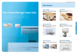
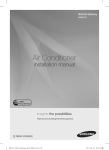
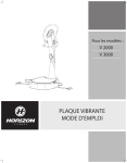
INSTALLATION MANUAL CHINESE ENGLISH MIM-D00 DMS (Data Management Server) K E C DB98-29919A(1) MIM-D00_IM_E_29919-1.indd 29 2008-09-10 ソタネト 1:27:35 Safety Precautions This installation manual describes how to install the DMS. For installation of other optional accessories, refer to the appropriate installation manual. WARNING CAUTION Read carefully this installation manual before installation and check if the DMS is installed correctly after installation. Do not attempt to install or repair this DMS by yourself. This DMS contains no user-serviceable parts. Always consult authorized service personnel for repairs. W hen moving, consult authorized service personnel for disconnection and installation of the DMS. Ensure that the wall is strong enough to support the weight of the DMS. Must install the DMS with rated power supply. The DMS must be installed according to the national electrical rules by an installation specialist. If you wish to uninstall the DMS, consult an authorized installation center. Do not use inflammable gases near the DMS. Do not install the DMS in a location where it will come into contact with combustible gases, machine oil, sulphide gas, etc. Avoid locations where acid/alkali solution or special spray is used. Choose a location that is dry and sunny, but not exposed to direct sunlight. Suitable temperature is between 0°C(32°F) and 39°C(102.2°F). Do not spill water into the DMS. Do not apply tensile strength to the cable to avoid cable damage. Do not press the buttons with a sharp object. Do not connect the power cable to the control terminal. If the DMS is installed in a hospital or other special places, it should not affect other electronic devices. E-2 MIM-D00_IM_E_29919-1.indd 2 2008-09-10 ソタネト 1:27:10 ENGLISH Contents SAFETY PRECAUTIONS ..................................................................... BEFORE INSTALLING THE DMS ...................................................... ACCESSORIES ..................................................................................... PRODUCT DESIGN ............................................................................ PRODUCT DIMENSIONS ................................................................... SYSTEM ARCHITECTURE ................................................................... COMPATIBLE DEVICES ...................................................................... INSTALLING THE DMS .................................................................... DMS EXTERNAL DISPLAY ............................................................. SETTING THE COMPUTER ENVIRONMENT ...................................... APPENDIX ......................................................................................... 2 4 5 5 6 7 8 9 14 15 22 E-3 MIM-D00_IM_E_29919-1.indd 3 2008-09-10 ソタネト 1:27:10 Before installing the DMS(Data Management Server) The following items need to be prepared before installation. WARNING • Only static IP must be used for the DMS. (Public IP or private IP) The DMS is a server and only static IP must be used. To access the DMS through the internet or with SNET series, the DMS address, which is the IP address, must be known. A static IP service from an internet service provider must be used if xDSL (ADSL, VDSL) is being used for internet connection. (Static IP costs more than dynamic IP.) Choosing between a private IP and a public static IP depends on whether the DMS needs to be controlled from an external location. General DSL service uses dynamic IP and cannot be used with the DMS. Refer to page 23~24 for explanation on technical terms. DMS IP A public IP is needed to access the DMS over the internet. (One public IP is needed for each DMS) A private IP may be used if the DMS need not be accessed over the internet. The DMS does not support *DHCP. Note *DHCP(Dynamic Host Configuration Protocol) An Internet protocol for automating the configuration of computers that use TCP/IP. DHCP is used to automatically assign IP addresses. In other words, the IP address of the host is supported only when the PC is on. NETWORK RELATED EQUIPMENTS Network equipments such as HUBs and network cables are not provided by Samsung. INSTALLATION NOTICE The DMS is recommended to be wall-mounted to prevent damage to the product and for safety issues. The LAN cable and the communication cables(C1,C2) from the centralized controllers must be installed in such a way that the wires can be connected to the DMS with ease. E-4 MIM-D00_IM_E_29919-1.indd 4 2008-09-10 ソタネト 1:27:10 Accessories Cable Tie (2) Cable Clamp(3) Rubber Hook(4) User's manual(1) Installation manual(1) M4X16 Screw(5) ENGLISH DMS(1) Caution The DMS must be installed by a trained installer. Ensure the main power is turned off before installing the DMS. The power cable and the communication cable must be installed according to the national electrical wiring regulations. (VCTF 2C x 0.75mm2 must be used for the communication and power cables) Ensure the cables are out of user’s reach. Product Design E-5 MIM-D00_IM_E_29919-1.indd 5 2008-09-10 ソタネト 1:27:11 Product Dimensions 8 219 135 8 28 Unit : mm 130 135 60 30 20 150 Serial Port Power Input LAN Port 101010 37 60 Reset Button Installation Method Fix the provided screws to the wall and use the four holes on the back of the DMS to hang the DMS on the wall. E-6 MIM-D00_IM_E_29919-1.indd 6 2008-09-10 ソタネト 1:27:13 ENGLISH System Architecture S-NET 3 DMS * HUB Centralized Controller Transmitter Transmitter Centralized Controller Network related equipments to be purchased separately SIM I/M Transmitter Power related equipments to be purchased separately * Power meter Connect one power meter to N number of outdoor units. Make sure the power meter capacity is greater than the total capacity of the outdoor units. Note roducts with ‘*’ are not Samsung products and must be P purchased separately. E-7 MIM-D00_IM_E_29919-1.indd 7 2008-09-10 ソタネト 1:27:14 Compatible Devices No. Devices Model Note 1 All System indoor/outdoor units such as: DVM, DVMH models, Indoor Unit DVM PLUS, DVM PLUS ΙΙ/ΙΙΙ, Outdoor Unit MINI DVM, HOME DVM, CAC models - 2 Interface Module MIM-B04A(for DVM, DVM PLUS etc.) MIM-B13(for DVM PLUS ΙΙ etc.) MIM-B13A(for DVM PLUS ΙΙ, ΙΙΙ etc.) - 3 Centralized Controller MCM-A202 MCM-A202A - 4 SIM I/M MIM-B12 Needed for power distribution *5 Watt-hour Meter RS485 comm. type Needed for power distribution (Please consult Samsung for compatible power meters) Note roducts with ‘* ’ are not Samsung products and must be purchased separately. P (Only selected power meters may be used for protocol compatibility issues.) Maximum Devices attachable The maximum number of devices attachable to the DMS is as follow: Devices Max. Note Centralized Controller 16 Must not exceed 16 Indoor Unit 256 Tracking error occurs if exceeded SIM I/M 8 Watt-hour Meter 64 8 power meters for each SIM I/M E-8 MIM-D00_IM_E_29919-1.indd 8 2008-09-10 ソタネト 1:27:16 Installing the DMS ENGLISH Connecting the Centralized Controller The centralized controllers must be installed to control the indoor units. 1 Loosen the two screws on the bottom of the DMS front cover. 2 Hold the bottom two sides of the DMS and push upwards to slide open the cover. (Sliding type cover) 3 Connect the provided power cable to the power terminal. 4 Connect the C1, C2 communication cable from the centralized controller to the J1 terminal of the DMS. (Communication will fail if the cable is not connected properly.) 5 Connect the LAN cable to the J6 terminal of the DMS. 6 Close the case cover after making sure the power cable is not pressed. 7 Assemble the cover as shown in the picture to avoid exposure of the stripped wires. POWER CABLE Centralized controller communication cable LAN CABLE Caution Maximum 16 centralized controllers can be connected to one DMS. Separate the power cable and the communication cable when installing the DMS. (The DMS may malfunction due to electrical disturbance.) E-9 MIM-D00_IM_E_29919-1.indd 9 2008-09-10 ソタネト 1:27:17 Installing the DMS (Continued) Connecting the SIM I/M The SIM I/M must be used for the power distribution function. 1 Loosen the two screws on the bottom of the DMS front cover. 2 Hold the bottom two sides of the DMS and push upwards to slide open the cover. (Sliding type cover) 3 Connect the provided power cable to the power terminal. 4 Connect the C1,C2 communication cable from the SIM I/M to the J1 terminal of the DMS. (Communication will fail if the cable is notconnected properly.) E-10 MIM-D00_IM_E_29919-1.indd 10 2008-09-10 ソタネト 1:27:19 Connect the LAN cable to the J6 terminal of the DMS. 6 Close the case cover after making sure the power cable is not pressed. 7 Assemble the cover as shown in the picture to avoid exposure of the stripped wires. ENGLISH 5 POWER CABLE Peak Power I/M communication cable LAN CABLE Caution Maximum 8 SIM I/Ms can be connected to one DMS. Maximum 8 power meters can be connected to one SIM I/M. Separate the power cable and the communication cable when installing the DMS. (The DMS may malfunction due to electrical disturbance.) E-11 MIM-D00_IM_E_29919-1.indd 11 2008-09-10 ソタネト 1:27:21 Installing the DMS (Continued) DMS PCB Option Switches 1 Reset Switch (SW01) : Resets the DMS when the DMS stops operating. (Pressing the reset switch will delete all current data. The switch must only be operated by the installer.) 2 DIP Switch(SW3) : Used for setting the DI mode. Operate only when the DI port is used. <Factory Default Settings> SW03 Note Refer to the appendix (page 22~23) for how to install the DI external signal control. E-12 MIM-D00_IM_E_29919-1.indd 12 2008-09-10 ソタネト 1:27:22 ENGLISH Using the DI external contact signal control (Optional) DIP Switch (SW03) : Use only for external contact signal control. Pattern DIP Switch 1 2 3 4 Control Details Pattern OFF OFF OFF OFF No response to the external contact signal control. (Factory default setting) 1 Used for emergency cases such fire. Responds when there is an input signal on DI-1 Operation: Turns off all the indoor units when there is an ON signal input, and disables the use of all the remote Pattern ON OFF OFF OFF controllers. During an emergency stop, 2 the DMS will ignore any request from the higher level controllers. The schedules will not operate as well. The indoor unit remote controllers will restore to the status previous to ON signal, when the external input signal changes to OFF. Responds when there is an input signal on DI-1 and DI-2. Operation: Changes the on/off status of all the indoor units Pattern OFF depending on the ON/OFF status of the DI-1 input. ON OFF OFF 3 Enables/disables the remote controllers depending on the ON/OFF status of the DI-2 input. (ON: enable/ OFF: disable) The schedules will run regardless of pattern 3. Responds when there is a pulse input on DI-1,2. Operation: Turns on all the indoor units when there is a pulse input on DI-1. Turns off all the indoor units when there is a pulse Pattern ON ON OFF OFF input on DI-2. 4 Turns off all the indoor units when there is a pulse input on DI-1, DI-2. (The pulse width is valid only for 0.5~1.0 sec.) The schedules will run regardless of pattern 4. Note Refer to the appendix (page 22~23) for how to install the DI external signal control. E-13 MIM-D00_IM_E_29919-1.indd 13 2008-09-10 ソタネト 1:27:22 DMS External Display 1 2 3 4 5 6 7 8 9 10 LED Status Display Power (Red) Power display. The power display is on when there’s a power input. Flickers every second if the CPU is operating normally. CPU Alive(Yellow) (The CPU is in waiting status and the CPU Alive display is off initially when powered up.) Linked (Green) Active (Green) Internet cable connection status display. The display is on when connected to the internet. Flickers during data transceive. RS485 Tx (Green) Flickers during data transmission from the DMS to the centralized controller. (Starts flickering once the tracking is complete.) RS485 Rx (Green) Flickers during data transmission from the centralized controller to the DMS. DI 1 Status (Green) Lights on when using the external contact signal control. (Refer to page 23) DI 2 Status (Green) Lights on when using the external contact signal control. (Refer to page 23) A/C Running (Green) DMS status indicator/Running status of indoor unit indicator You may setup A/C Running LED to indicate either DMS status or Indoor unit operation. - DMS status: Green light will flicker every 5 seconds when DMS operates normally. - Running status of indoor unit: Solid green light will turn on when the indoor units operate normally. (at least 1 indoor unit) Error (Green) Lights on if there is an error on at least one indoor or outdoor unit. Also Lights on when there is a communication error. E-14 MIM-D00_IM_E_29919-1.indd 14 2008-09-10 ソタネト 1:27:23 Setting the Computer Environment The following device and accessory is needed: ENGLISH 1 Computer with a LAN Card *Cross Cable or a HUB 2 Setting the computer environment. Must have Internet Explorer 6.0 or above installed. Please install the internet explorer 6.0 or above through Windows Update Must have JRE 1.3.1 or above installed JRE can be downloaded from http://java.sun.com/j2se or automatically by connecting to the DMS through the internet. 3 Connection Method (Choose one of the two methods list below.) Connecting the DMS directly to the computer Computer * (Cross Cable) Connecting the DMS using a HUB HUB Computer (Direct Cable) Note *Cross Cable: A cross cable is used when connecting two PCs directly. A direct cable is used to connect the PC to a HUB, and a cross cable is used to connect between two PCs or between a PC and a DMS. The cross cable can be purchased at any computer stores. E-15 MIM-D00_IM_E_29919-1.indd 15 2008-09-10 ソタネト 1:27:24 Setting the Computer Environment (Continued) 4 Setting the computer environment to access the DMS for the first time. All the environment of the DMS is set by connecting to the DMS. In order to access the DMS, the computer environment must be set as follow: Choose one of the two methods to access the DMS. The default IP setting of the DMS is 192.168.0.2 1) Change the computer IP address (Recommended) Set the network environment of the computer connected to the DMS as follow: Click on the ‘My Network’ icon on the desktop to access the above screen. Right click and press ‘properties’. Right click on the ‘Local Area Network’ icon and press ‘properties’. Select ‘Internet protocol(TCP/IP)’ and press ‘properties’. 2) Run the route command Start Run Type in the following command Enter Route add 192.168.0.0 mask 255.255.255.0 *Computer_IP The computer IP refers to the IP address of the computer connected or that is to be connected to the DMS Type in 192.168.0.1 when using a private IP. Note Refer to page 24~25 for setting the IP address. E-16 MIM-D00_IM_E_29919-1.indd 16 2008-09-10 ソタネト 1:27:26 ENGLISH Connect to the internet. Run the internet explorer and type in the following address. http://192.168.0.2 If the connection is successful, the following front page will load. The DMS will prompt for a user ID and a password as shown above. The factory default user setting is as follow: admin 1234 Type in the ID and the password and click on LOGIN. Change the user setting if needed for security reasons. E-17 MIM-D00_IM_E_29919-1.indd 17 2008-09-10 ソタネト 1:27:26 Setting the Computer Environment (Continued) The following screen is displayed if the login is successful. Click on SYSTEM ENVIRONMENT. E-18 MIM-D00_IM_E_29919-1.indd 18 2008-09-10 ソタネト 1:27:26 ENGLISH Click on the ‘Edit’ button to change the language settings. (Default:English) The system will start up automatically once the language is set. Click on the ‘Edit’ button to change the DMS network settings. The system will start up automatically once the settings are saved. Click on the ‘Edit’ button to change the time settings. Set the time for accurate error time logs and schedule controls. Click on the ‘Edit’ button to change the Operation mode of A/C Running. - When you click ‘Edit’ button, it will change to ‘Save’ button. Select the mode you wish to set. - DMS status: Green light will flicker every 5 seconds when DMS operates normally. - Running status of indoor unit: Solid green light will turn on when the indoor units operate normally. (at least 1 indoor unit) Click ‘Save’ button. - Changed setting will be saved. Note For detail instructions on setting System Environment, refer to user’s manual. MIM-D00_IM_E_29919-1.indd 19 E-19 2008-09-10 ソタネト 1:27:27 Setting the Computer Environment (Continued) Tracking Click on the tracking button once the environment is set. The above screen will be displayed. Select either the group mode tracking or the room mode tracking. Group mode tracking: Control the indoor units according to the RMC address. Room mode tracking: - Control the indoor units according to the MAIN address of the indoor units. - Indoor unit MAIN address and the RMC address will be displayed. The message “Tracking...Please wait.” will be displayed while tracking. Tracking will take at least a few seconds to at most three minutes. E-20 MIM-D00_IM_E_29919-1.indd 20 2008-09-10 ソタネト 1:27:27 ENGLISH The following screen is display if tracking is successful. Click on the edit button to change the names of the indoor units and the centralized controllers. The basic settings for the internet control is set. Please refer to the user manual for detailed information on internet control. Note For detail instructions on Tracking, refer to user’s manual. E-21 MIM-D00_IM_E_29919-1.indd 21 2008-09-10 ソタネト 1:27:27 Appendix DI/DO circuit (Optional) 5 DI-2 2 DO-2 4 External contact signal control (ON/OFF control of all the indoor units) DI-2 (Digital Input) External contact signal control (ON/OFF control of all the indoor units) DO-1 (Digital Output) Outputs 12V if at least one indoor unit is running. (External circuit may be built for display using the 12V output) Equivalent to the ‘A/C Running’ LED on the DMS external display. Outputs as the settings on the Operation mode of A/C Running LED. - DMS status: Green light will flicker every 5 seconds when DMS operates normally. - Running status of indoor unit: Solid green light will turn on when the indoor units operate normally. (at least 1 indoor unit) DO-2 (Digital Output) Outputs 12V if there is an error on the indoor or outdoor unit or if communication error occurs. (External circuit may be built for display using the 12V output) Equivalent to the ‘Error’ LED on the DMS external display. Serial communication for environment setup purpose. port Note 22 3 DI-1 (Digital Input) E-22 DO-1 MIM-D00_IM_E_29919-1.indd DI-1 1 Consult Samsung Electronics when building an external circuit for display. 2008-09-10 ソタネト 1:27:28 ENGLISH DI(Digital Input) Circuitry (Optional) Pattern 2 (May be used for connection with a fire sensor) ��� Emergency Stop/Resume Operation ���� ���� No Connection Pattern 3 ��� Run/Stop A/C ���� Enable/Disable remote control ���� Pattern 4 (Pulse signal control) ��� Run ���� Stop ���� Note Refer to page 12~13 for PCB DIP s/w settings when using the DI external signal control. E-23 MIM-D00_IM_E_29919-1.indd 23 2008-09-10 ソタネト 1:27:28 Appendix (Continued) Setting the IP Address 1 When using DSL connection 1) Using a private IP : used if the internet control is not needed and the DMS is controlled only from one place. Connecting the DMS and the controller 1:1 DMS SNET-i *Cross Cable Private IP : 192.168.0.2 Private IP : 192.168.0.1 Computer DMS *Cross Cable Private IP : 192.168.0.2 Private IP : 192.168.0.1 (A separate LAN Card is needed if the user wants to use the computer to access both the internet and the DMS) 2) Using a static IP : used for external control over the internet. SNET-i HUB Computer DMS Direct Cable �������� Public IP 2 Please consult the network administrator when deciding the DMS IP address. (Must consult for firewall issues.) E-24 MIM-D00_IM_E_29919-1.indd 24 2008-09-10 ソタネト 1:27:29 ENGLISH 3 IP terms explanation Public IP Static IP Dynamic IP Private IP Static IP Dynamic IP The DMS requires an IP address to be connected to the internet and to allow computers to access the DMS. Public IP Public IP addresses are IP addresses that are visible to the public. Static IP : An address assigned by the internet service provider to be its permanent address on the internet Dynamic IP : Temporary IP address assigned by the internet service provider that changes every time the computer connects to the internet. Private IP The internet cannot be accessed using a private IP unless a HUB, or an internet sharing program is used. However, if a private IP is used, the computer or the DMS cannot be accessed from the internet. There are three blocks of private IP addresses: - 10.0.0.0 through 10.255.255.255 - 172.16.0.0 through 172.31.255.255 - 192.168.0.0 through 192.168.255.255 A private IP is not assigned by the internet service providers. Internet service providers assign only public IPs, whether static or dynamic. E-25 MIM-D00_IM_E_29919-1.indd 25 2008-09-10 ソタネト 1:27:31 Appendix (Continued) IP Setup Error 1 Initial connection error (occurs only when using a private IP) A number of DMS’ are connected on the same network The default factory IP setting of all the DMS’ are the same and when they are connected on the same network, the IP address of the DMS’ will collide. Please set the network environment of the DMS one at a time and connect all the DMS’ once all the IP addresses are set differently. Computer DMS 1 Initial IP : 192.168.0.2 The computer will not know which DMS has the IP address 192.168.0.2. DMS 2 Initial IP : 192.168.0.2 DMS 3 Initial IP : 192.168.0.2 DMS 4 Initial IP : 192.168.0.2 E-26 MIM-D00_IM_E_29919-1.indd 26 2008-09-10 ソタネト 1:27:32 Installation Errors 1 Check the centralized controller and transmitter models. 2 Check the communication status between the centralized controller and the transmitter. Devices If the communication is normal Centralized The indoor units are controlled Controller according to the on/off buttons ‘U’ is displayed on the right side of the 7-segment display Transmitter ENGLISH Check points when tracking fails and the installation information of the indoor and outdoor units are not available. If the communication fails The power LED and the room LEDs flicker periodically Nothing is displayed on the right side of the 7-segment display Only ‘d’ is displayed on the right side of the 7-Segment display The 7-Segment display of the transmitter is as follow: Left : The main address of the indoor units are displayed if the communication is normal. Right : The RMC address of the indoor units are displayed followed by the following alphabets. d - Displayed when waiting for communication with the centralized controller U - Displayed when the communication is normal None - Communication with the centralized controller broken check the connection status 3 Check the polarity of the communication cables between the DMS and the centralized controllers. (The ‘RS485 Rx’ LED on the DMS display is off if the communication fails) Communication will fail if the C1, C2 polarity is changed. Check for broken wires. E-27 MIM-D00_IM_E_29919-1.indd 27 2008-09-10 ソタネト 1:27:35 MIM-D00_IM_E_29919-1.indd 28 2008-09-10 ソタネト 1:27:35