1
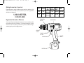
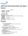
2821,2822,382083-01,00
5/8/02
12:42 PM
Page 2
Black and Decker Industrial Tool Co., 701 East Joppa Road, Baltimore, MD 21286
Printed in USA (JAN03-CD-1)
Copyright © 2002
Form # 382083-01
The following are trademarks for one or more DeWALT power tools: the yellow and black color scheme; the “D” shaped air intake grill; the array
of pyramids on the handgrip; the kit box configuration; and the array of lozenge-shaped humps on the surface of the tool.
2821,2822,382083-01,00
5/8/02
12:42 PM
Page 3
TM
Instruction Manual
2821 2822
Adjustable Clutch Driver/Drill
2821,2822,382083-01,00
5/8/02
12:42 PM
Page 4
Getting the most out of your tool.
Please take time to read this manual and pay particular attention to the
safety rules we’ve provided for your protection. If you have any questions
about your tool please call:
Cat #
Voltage
2821
9.6V
1-800-9-BD TOOL
2822
12.0V
Grip
Style
Chuck
Capacity
Battery
Pack
Mid.
Standard
Mid.
Standard
3/8"
Standard 0-350/0-1000
3/8"
Standard 0-400/0-1200
RPM
(1-800-923-8665)
TORQUE ADJ.
COLLAR
Ergonomics that make a difference
GEAR SHIFTER
Your driver/drill has been designed with concern for work conditions which
have quite an effect on the operator. The innovative design of this tool
allows for comfort in handling, neutral wrist positions, balanced weight,
excellent gripping, and low trigger pressure.
KEYLESS
CHUCK
FWD/REV. CONTROL
BUTTON
TRIGGER SWITCH
BATTERY PACK
RUBBER
GRIP
2821,2822,382083-01,00
5/8/02
12:42 PM
Page 1
GENERAL SAFETY RULES – FOR ALL
BATTERY OPERATED TOOLS
•
WARNING! Read and understand all instructions. Failure to follow all
instructions listed below may result in electric shock, fire and/or serious
personal injury.
•
SAVE THESE INSTRUCTIONS
•
WORK AREA
•
•
•
•
Keep your work area clean and well lit. Cluttered benches and dark areas
invite accidents.
Do not operate power tools in explosive atmospheres, such as in the
presence of flammable liquids, gases, or dust. Power tools create sparks
which may ignite the dust or fumes.
Keep bystanders, children, and visitors away while operating a power tool.
Distractions can cause you to lose control.
•
TOOL USE AND CARE
•
ELECTRICAL SAFETY
•
•
•
Do not abuse the cord. Never use the cord to carry the tools or pull the plug
from an outlet. Keep cord away from heat, oil, sharp edges or moving
parts. Replace damaged cords immediately. Damaged cords increase the
risk of electric shock.
A battery operated tool with integral batteries or a separate battery pack
must be recharged only with the specified charger for the battery. A charger
that may be suitable for one type of battery may create a risk of fire when used
with another battery.
Use battery operated tool only with the specifically designed battery pack.
Use of any other batteries may create a risk of fire.
•
•
•
•
PERSONAL SAFETY
•
power tools may result in serious personal injury,
Dress properly. Do not wear loose clothing or jewelry. Contain long hair.
Keep your hair, clothing, and gloves away from moving parts. Loose
clothing, jewelry, or long hair can be caught in moving parts. Air vents often
cover moving parts and should also be avoided.
Avoid accidental starting. Be sure switch is in the locked or off position
before inserting battery pack. Carrying tools with your finger on the switch
or inserting the battery pack into a tool with the switch on invites accidents.
Remove adjusting keys or switches before turning the tool on. A wrench or
key that is left attached to a rotating part of the tool may result in personal
injury.
Do not overreach. Keep proper footing and balance at all times. Proper
footing and balance enables better control of the tool in unexpected
situations.
Use safety equipment. Always wear eye protection. Dust mask, non-skid
safety shoes, hard hat, or hearing protection must be used for appropriate
conditions.
Stay alert, watch what you are doing and use common sense when
operating a power tool. Do not use tool while tired or under the influence of
drugs, alcohol, or medication. A moment of inattention while operating
•
1
Use clamps or other practical way to secure and support the workpiece to a
stable platform. Holding the work by hand or against your body is unstable
and may lead to a loss of control.
Do not force tool. Use the correct tool for your application. The correct tool
will do the job better and safer and the rate for which it is designed.
Do not use tool if switch does not turn it on or off. Any tool that cannot be
controlled with the switch is dangerous and must be repaired.
Disconnect battery pack from tool or place the switch in the locked or off
position before making any adjustments, changing accessories, or storing
the tool. Such preventative safety measures reduce the risk of starting the
tool accidentally.
Store idle tools out of reach of children and other untrained persons. Tools
are dangerous in the hands of untrained users.
When battery pack is not in use, keep it away from other metal objects
like: paper clips, coins, keys, nails, screws, or other small metal objects
2821,2822,382083-01,00
5/8/02
12:42 PM
Page 2
SERVICE
• lead from lead-based paints,
• crystalline silica from bricks and cement and other masonry products, and
• arsenic and chromium from chemically-treated lumber (CCA).
Your risk from these exposures varies, depending on how often you do this type
of work. To reduce your exposure to these chemicals: work in a well ventilated
area, and work with approved safety equipment, such as those dust masks that
are specially designed to filter out microscopic particles.
• Avoid prolonged contact with dust from power sanding, sawing, grinding,
drilling, and other construction activities. Wear protective clothing and
wash exposed areas with soap and water. Allowing dust to get into your
mouth, eyes, or lay on the skin may promote absorption of harmful
chemicals.
• The label on your tool may include the following symbols.
•
V
•
•
•
•
that can make a connection from one terminal to another. Shorting the
battery terminals together may cause sparks, burns, or a fire.
Maintain tools with care. Keep cutting tools sharp and clean. Properly
maintained tools, with sharp cutting edges are less likely to bind and are
easier to control.
Check for misalignment or binding of moving parts, breakage of parts, and
any other condition that may affect the tools operation. If damaged, have
the tool serviced before using. Many accidents are caused by poorly
maintained tools.
Use only accessories that are recommended by the manufacturer for your
model. Accessories that may be suitable for one tool, may become hazardous
when used on another tool.
Tool service must be performed only by qualified repair personnel. Service
or maintenance performed by unqualified personnel could result in a risk of
injury.
When servicing a tool, use only identical replacement parts. Follow
instructions in the Maintenance section of this manual. Use of unauthorized
parts or failure to follow Maintenance Instructions may create a risk of electric
shock or injury.
…/min
volts
alternating current
direct current
revolutions or reciprocation per minute
ADDITIONAL SAFETY RULES
FOR BATTERY CHARGERS
ADDITIONAL SAFETY RULES
This manual contains important safety and operating instructions.
• Before using charger, read all instructions and cautionary markings on (1)
charger, (2) battery pack, and (3) product using battery pack.
• DANGER: Do not probe with conductive objects. 120 volts present at
charging terminals. Danger of electric shock or electrocution.
• DANGER: If battery pack case is cracked or damaged, do not insert into
charger. Danger of electric shock or electrocution.
• The charger and battery pack are specifically designed to work together. DO
NOT attempt to charge the battery pack with any chargers other than the ones
in this manual.
• Hold tool by insulated gripping surfaces when performing an operation
where the cutting tool may contact hidden wiring or its own cord. Contact
with a “live” wire will make exposed metal parts of the tool “live” and shock
the operator.
CAUTION: Some tools with large battery packs will stand upright on the
battery pack but may be easily knocked over. When not in use, place tool on its
side on a stable surface where it will not cause a tripping or falling hazard.
WARNING: Some dust created by power sanding, sawing, grinding, drilling,
and other construction activities contains chemicals known to cause cancer, birth
defects or other reproductive harm. Some examples of these chemicals are:
2
2821,2822,382083-01,00
5/8/02
12:42 PM
Page 3
•
•
•
•
•
•
•
•
•
•
•
Do not expose charger to rain or snow.
These chargers are not intended for any uses other than charging B&D
rechargeable batteries. Any other uses may result in risk of fire, electric shock
or electrocution.
To reduce risk of damage to electric plug and cord, pull by plug rather than
cord when disconnecting charger.
Make sure cord is located so that it will not be stepped on, tripped over, or
otherwise subjected to damage or stress.
An extension cord should not be used unless absolutely necessary. Use of
improper extension cord could result in risk of fire, electric shock, or
electrocution.
An extension cord must have adequate wire size (AWG or American Wire
Gauge) for safety. The smaller the gauge number of the wire, the greater the
capacity of the cable, that is 16 gauge has more capacity than 18 gauge.
When using more than one extension to make up the total length, be sure
each individual extension contains at least the minimum wire size.
Recommended Minimum AWG Size for Extension Cords
Total Extension Cord Length (feet)
25
50
75
100
125
150
175
Wire Gauge
18
18
16
16
14
14
12
The charger is ventilated through slots in the top and the bottom of the
housing. Do not place any object on top of charger or place the charger on a
soft surface that might block the ventilation slots and result in excessive
internal heat. Place the charger in a position away from any heat source.
Do not operate charger with damaged cord or plug — have them replaced
immediately.
Do not operate charger if it has received a sharp blow, been dropped, or
otherwise damaged in any way; take it to an authorized service center.
Do not disassemble charger; take it to an authorized service center when
service or repair is required. Incorrect reassembly may result in a risk of
electric shock, electrocution or fire.
•
•
•
To reduce risk of electric shock, unplug charger from outlet before attempting
any cleaning. Removing the battery pack will not reduce this risk.
NEVER attempt to connect 2 chargers together.
DO NOT store or use the tool and battery pack in locations where the
temperature may reach or exceed 105°F (such as outside sheds or metal
buildings in summer).
The charger is designed to operate on standard household electrical power
(120 Volts). Do not attempt to use it on any other voltage!
ADDITIONAL SAFETY RULES
FOR BATTERY PACKS
The battery pack is not fully charged out of the carton! First read the safety
instructions below. Then follow charging notes and procedures.
READ ALL INSTRUCTIONS
•
•
•
•
3
Do not incinerate the battery pack even if it is severely damaged or is
completely worn out.The battery pack can explode in a fire.
A small leakage of liquid from the battery pack cells may occur under extreme
usage or temperature conditions. This does not indicate a failure. However, if
the outer seal is broken and this leakage gets on your skin:
a. Wash quickly with soap and water.
b. Neutralize with a mild acid such as lemon juice or vinegar.
c. If battery liquid gets into your eyes, flush them with clean water for a
minimum of 10 minutes and seek immediate medical attention. (MEDICAL
NOTE: The liquid is 25-35% solution of potassium hydroxide.)
Never attempt to open the battery pack for any reason. If the plastic housing of
the battery pack breaks or cracks, immediately discontinue use and do not
recharge.
Do not carry extra battery packs in aprons, pockets, or tool boxes along with
other metal objects. Battery pack could be short circuited causing damage to
the battery pack and possibly causing severe burns or fire.
2821,2822,382083-01,00
5/8/02
12:42 PM
Page 4
•
•
Charge the battery packs only in B&D chargers.
NOTE: Review and observe all of the “Important Charging Notes” in the
charger instruction section of this manual.
• NOTE: The batteries in your battery pack are the nickel–cadmium type.
Cadmium is considered to be a toxic material by the Environmental Protection
Agency. Before disposing of damaged or worn out Nickel–Cadmium battery
packs, check with your state Environmental Protection Agency to find out
about special restrictions on the disposal of these battery packs or return
them to a certified service center for recycling.
• NOTE: Battery storage and carrying caps are provided for use
whenever the battery is out of the tool or charger. Remove cap
before placing battery in charger or tool.
WARNING: Do not store or carry battery so that metal
objects can contact exposed battery terminals. For example,
do not place battery in aprons, pockets, tool boxes, product kit
boxes, drawers, etc. with loose nails, screws, keys, etc. without battery cap.
Without cap in place, battery could short circuit causing fire or burns or
damage to battery.
replacement battery packs, be sure to include catalog number and voltage:
(9.6 Volt-97148, 97048) (12.0 Volt-97150, 97051).
Chargers 97014, 97015
Your battery can be charged in the 97014 (1 Hour Charger) or the 97015
Charger. Be sure to read all safety instructions before using your charger.
Charging Procedure
These chargers require no adjustment and are designed to be as easy as
possible to operate. Simply place your battery pack into the receptacle of a
plugged in charger (FIG.1) and it will automatically charge the pack.
97014 (1 HOUR CHARGER)
1. Plug the charger into an appropriate AC power outlet.
2. Insert the battery pack into the charger, as shown in FIG.1, making
sure the pack is fully seated in the charger. The red (charging) light will
blink continuously indicating that the charging process has started.
3. The battery pack will be fully charged in about 1 hour. The completion
of charge will be indicated by the red light remaining ON continuously.
The pack is fully charged and may be used at this time or left in the
charger.
97015
1. Plug the charger into an appropriate AC power outlet.
2. Insert the battery pack into the charger, as shown in FIG. 1, making
sure the pack is fully seated in the charger. The red (charging) light will
blink continuously indicating that the charging process has started.
3. The completion of charge will be indicated by the red light remaining
ON continuously. The pack is fully charged and may be used at this
time or left in the charger.
Leaving the battery pack in the charger: When the red light remains ON,
Battery Packs
Your tool uses a 9.6 Volt or a 12.0 Volt battery pack. When ordering
Figure 1
4
2821,2822,382083-01,00
5/8/02
12:42 PM
Page 5
the charger has switched to its “equalize charge” mode which lasts
approximately 4 hours, after which the charger will switch to “maintenance
charge” mode. The battery pack can be removed at any time during these
charge cycles, but will only be fully charged if the red light is continuously
ON. The charger and battery pack can be left connected with the red light
glowing indefinitely. The charger will keep the battery pack fresh and fully
charged. A battery pack will slowly lose its charge when kept out of the
charger. If the battery pack has not been kept on maintenance charge, it
may need to be recharged before use. A battery pack may also slowly lose
its charge if left in a charger that is not plugged into an appropriate AC
source.
24°C). DO NOT charge the battery pack in an air temperature below
+40°F(+4.5°C), or above +105°F (+40.5°C). This is important and will
prevent serious damage to the battery pack.
2. The charger and battery pack may become warm to touch while
charging. This is a normal condition, and does not indicate a problem.
3. If the battery pack does not charge properly — (1) Check current at
receptacle by plugging in a lamp or other appliance, (2) Check to see if
receptacle is connected to a light switch which turns power off when
you turn out the lights. (3) Move charger and battery pack to a location
where the surrounding air temperature is approximately 65°F - 75°F
(18°- 24°C). (4) If charging problems persist, take or send the tool,
battery pack and charger to your local service center.
4. The battery pack should be recharged when it fails to produce sufficient
power on jobs which were easily done previously. DO NOT CONTINUE
to use under these conditions. Follow the charging procedure. You may
also charge a partially used pack whenever you desire with no adverse
affect on the battery pack.
3
2
Trouble Indicators: These chargers are designed to detect certain problems
that can arise with battery packs which would be indicated by the red light
flashing at a fast rate (and continuous beeping for 97014). If this occurs, reinsert battery pack. If problem persists, try a different battery pack to
determine if the charger is OK. If the new pack charges correctly, then the
original pack is defective and should be returned to a service center for
recycling. If the new battery pack elicits the same trouble indication as the
original, have charger tested at an authorized service center.
4
PROBLEM POWER LINE (97015)
When these chargers are used with some portable power sources such as
generators or sources that convert DC to AC, the chargers may temporarily
suspend operation, flashing the red light with two fast blinks followed by
a pause. This indicates the power source is out of limits.
Important Charging Notes
1. Longest life and best performance can be obtained if the battery pack is
charged when the air temperature is between 65°F and 75°F (18°-
Figure 3
Figure 2
RELEASE BUTTON
5
2821,2822,382083-01,00
5/8/02
12:42 PM
Page 6
5. Under certain conditions, with the charger plugged in to the power
supply, the exposed charging contacts inside the charger can be
shorted by foreign material. Foreign materials of a conductive nature
such as, but not limited to, steel wool, aluminum foil, or any buildup of
metallic particles should be kept away from charger cavities. Always
unplug the charger from the power supply when there is no battery
pack in the cavity. Unplug charger before attempting to clean.
6. Do not freeze or immerse charger in water or any other liquid.
7. WARNING: Don't allow any liquid to get inside charger. Electric shock
may result. To facilitate the cooling of the battery pack after use, avoid
placing the charger or battery pack in a warm environment such as in a
metal shed, or an uninsulated trailer.
8. CAUTION: Never attempt to open the battery pack for any reason. If the
plastic housing of the battery pack breaks or cracks, return to a service
center for recycling.
READ ALL OF THE INSTRUCTIONS IN THE BATTERY CHARGER SECTION
OF THIS MANUAL BEFORE ATTEMPTING TO CHARGE THE battery pack
FOR YOUR TOOL.
Removing and Installing the Battery Pack
NOTE: YOUR BATTERY PACK WILL NOT BE FULLY CHARGED OUT OF THE
CARTON.
To install the battery pack into the tool handle, align the base of the tool with
the notch inside the tool’s handle and slide the battery pack firmly into the
handle until you hear the lock snap into place as shown in Figures 2 and 3.
To remove the battery pack from the tool, press the release buttons, as
shown in Figure 3, and firmly pull the battery pack out of the tool handle.
Insert it into the charger as described in the charger section of this
instruction manual.
Important!
This product is not user serviceable. There are no user serviceable parts
inside the charger. Servicing at an authorized service center is required to
avoid damage to static sensitive internal components.
VARIABLE SPEED
TRIGGER SWITCH
DEPRESS FOR
REVERSE
Figure 4
Figure 5a
Figure 5b
Figure 5c
CENTER POSITION: LOCKED OFF
6
DEPRESS FOR
FORWARD
2821,2822,382083-01,00
5/8/02
12:42 PM
Page 7
NOTE: Continuous use in variable speed range is not recommended. It may
damage the switch and should be avoided.
To turn the tool “ON,” squeeze the trigger switch. To turn the tool “OFF,”
release the trigger switch (Figure 4). Your driver/drill is equipped with a
brake. The chuck will stop as soon as the trigger switch is fully released.
Forward/Reverse Control Button
Your driver/drill is equipped with a variable speed switch which enables you
to select the best speed for a particular application. The farther you squeeze
the trigger, the faster the tool will operate.
A forward/reverse control button determines the direction of the tool and
also serves as a “lock off” button. To select forward rotation, release the
trigger switch and depress the forward/reverse control button on the right
side of the tool, as shown in Figure 5a.
Use lower speeds for starting holes without a centerpunch, drilling in metals
or plastics, driving screws and drilling ceramics, or in any application
requiring high torque. Higher speeds are better for drilling in wood, wood
compositions and for using abrasive and polishing accessories. For
maximum tool life, use variable speed only for starting holes or fasteners.
To select reverse, depress the forward/reverse control button on the left
side of the tool as shown in Figure 5b. The center position of the control
button locks the tool in the “OFF” position as shown in Figure 5c.
When changing the position of the forward/reverse control button, be sure
the trigger is released.
Figure 6
NOTE: The first time the tool is run after changing the direction of rotation,
you may hear a click on start up. This is normal and does not indicate a
problem.
TORQUE
ADJUSTMENT
COLLAR
Torque Adjustment Collar
Your driver/drill has an adjustable torque screwdriver mechanism for
driving and removing a wide array of fastener shapes and sizes.
DUAL RANGE
GEAR SHIFTER
Circling the collar are numbers ranging from 0 to 5, and a drill bit symbol.
These numbers (and half numbers designated by dots on the collar) are
used to set the clutch to deliver a torque range.
The higher the number on the collar, the higher the torque and the larger the
fastener which can be driven. To select any of the numbers, rotate until the
desired number aligns with the selector, shown in Figure 6.
1
7
2821,2822,382083-01,00
5/8/02
12:42 PM
Page 8
Dual Range Gearing
Troubleshooting Tip!
The dual range feature of your driver/drill allows you to shift gears for
greater versatility.
If you are having trouble changing gears, make sure that the dual range gear
shifter is either completely pushed forward or completely pushed back.
To select the low speed, high torque setting, turn the tool off and permit the
unit to stop. Slide the gear shifter forward (towards the chuck - position 1),
as shown in Figure 6.
Keyless Chuck
Your tool features a keyless chuck for greater convenience. To insert a drill
bit or other accessory, follow the steps listed below.
To select the high speed, low torque setting, turn the tool off and permit the
unit to stop. Slide the gear shifter back (away from chuck - position 2).
1. Lock the trigger switch in the OFF position as shown in Figure 5c.
2. Grasp the rear half of the chuck with one hand and use your other hand
to rotate the front half counterclockwise, as shown in Figure 7. Rotate
far enough so that the chuck opens sufficiently to accept the desired
accessory.
3. Insert the bit or other accessory about 3/4" into the chuck and tighten
securely by holding the rear half of the chuck and rotating the front
portion in the clockwise direction.
To release the accessory, repeat step 2 listed above.
WARNING: Do not attempt to tighten drill bits (or any other accessory) by
gripping the front part of the chuck and turning the tool on. Damage to the
Refer to the chart below to determine the available speeds of your model of
driver/drill.
Figure 7
4
4
5
5
3
NOTE: Do not change gears when the tool is running.
3
Helpful Hint!
Be sure to tighten chuck with two hands- one
on both the rear sleeve and the forward sleeve
for maximum tightness.
Figure 8
8
Figure 9
2821,2822,382083-01,00
5/8/02
12:42 PM
Page 9
chuck and personal injury may result. Always lock off trigger switch when
changing accessories.
Drilling
1. Use sharp drill bits only. For WOOD, use twist drill bits, spade bits,
power auger bits, or hole saws. For METAL, use high speed steel twist
drill bits or hole saws. For MASONRY, such as brick, cement, cinder
block, etc., use carbide-tipped bits.
2. Be sure the material to be drilled is anchored or clamped firmly. If drilling
thin material, use a “back-up” block to prevent damage to the material.
3. Always apply pressure in a straight line with the bit. Use enough
pressure to keep the drill bit biting, but do not push hard enough to stall
the motor or deflect the bit.
4. Hold tool firmly to control the twisting action of the drill.
5. IF DRILL STALLS, it is usually because it is being overloaded. RELEASE
TRIGGER IMMEDIATELY, remove drill bit from work, and determine
cause of stalling. DO NOT CLICK TRIGGER OFF AND ON IN AN ATTEMPT
TO START A STALLED DRILL – THIS CAN DAMAGE THE DRILL.
6. To minimize stalling on breaking through the material, reduce pressure
on drill and ease the bit through the last fractional part of the hole.
7. Keep the motor running when pulling the bit back out of a drilled hole.
This will help prevent jamming.
8. With variable speed drills there is no need to center punch the point to
be drilled. Use a slow speed to start the hole and accelerate by
squeezing the trigger harder when the hole is deep enough to drill
without the bit skipping out. Operate at full on after starting the bit.
Chuck Removal
Always wear eye protection.
Lock off the tool and turn the adjustment collar to the “drill” position and
low speed gear shifter to position 1. Tighten the chuck around the shorter
end of a hex key (not supplied) of 1/4" or greater size. Using a wooden
mallet or similar object, strike the longer end in the clockwise direction, as
shown in Figure 8. This will loosen the screw inside the chuck.
Open chuck jaws fully, insert screwdriver (or Torx tool if required) into front
of chuck between jaws to engage screw head. Remove screw by turning
clockwise (left-hand-thread). Place hex key in chuck and tighten, as shown
in Figure 9. Using a wooden mallet or similar object, strike key sharply in the
counter clockwise direction. This will loosen the chuck so that it can be
unscrewed by hand.
Chuck Installation
Lock off the tool. Screw the chuck on by hand as far as it will go. Tighten the
chuck around the shorter end of a 1/4" or larger hex key (not supplied) strike
the longer end in the clockwise direction with a wooden mallet, as shown in
Figure 8. Insert and tighten the screw by turning in a counter clockwise
direction.
Operation as a Drill
Drilling in Wood
Turn the collar to the drill bit symbol. Install and tighten the desired drill bit in
the chuck. Select the desired speed/torque range using the dual range gear
shifter to match the speed and torque to the planned operation.
Holes in wood can be made with the same twist drills used for metal. These
bits may overheat unless pulled out frequently to clear chips from the flutes.
For larger holes, use low speed wood bits. Work that is likely to splinter
should be backed up with a block of wood.
Follow these instructions for best results when drilling.
9
2821,2822,382083-01,00
5/8/02
12:42 PM
Page 10
and grease may be removed from the exterior of the charger using a cloth or
soft non-metallic brush. Do not use water or any cleaning solutions.
Drilling in Metals
Use a cutting lubricant when drilling metals. The exceptions are cast iron
and brass which should be drilled dry. The cutting lubricants that work best
are sulphurized cutting oil or lard oil; bacon grease will also serve the
purpose.
Accessories
Recommended accessories for use with your tool are available at extra cost
from your distributor or local service center. A complete listing of service
centers is included with your tool.
Drilling in Masonry
CAUTION: The use of any non-recommended accessory may be hazardous.
Use carbide tipped masonry bits at low speeds. Keep even force on the drill
but not so much that you crack the brittle materials. A smooth, even flow of
dust indicates the proper drilling rate.
If you need any assistance in locating any accessory call 1-800-9-BD TOOL
(1-800-923-8665) or contact Black & Decker (U.S.) Inc., Consumer Services
Department, P.O. Box 618, 626 Hanover Pike, Hampstead, MD 21074.
Operation as a Screwdriver
IMPORTANT!
Select the desired speed/torque range using the dual range gear shift lever
on the top of tool to match the speed and torque to the planned operation.
To assure product safety and reliability, particularly for Double Insulated
tools, repairs, maintenance and adjustment (excluding maintenance
described in this manual) should be performed by B&D service centers or
authorized service centers, using identical B&D replacement parts.
Insert the desired fastener accessory into the chuck as you would any drill
bit. Set the torque adjustment collar (Figure 6). Make a few practice runs in
scrap or unseen areas to determine the proper position of the clutch collar.
MAINTENANCE
CLEANING: With the motor running, blow dirt and dust out of all air vents
with dry air at least once a week. Wear safety glasses when performing this.
Exterior plastic parts may be cleaned with a damp cloth and mild detergent.
Although these parts are highly solvent resistant, NEVER use solvents.
Charger Cleaning Instructions:
WARNING: Disconnect the charger from the AC outlet before cleaning. Dirt
10
2821,2822,382083-01,00
5/8/02
12:42 PM
Page 11
Every B&D tool is of the highest quality.
If you wish to contact us regarding this product, please call toll
free between 8:00am and 8:00pm ET, seven days a week:
1-800-9-BD TOOL
(1-800-923-8665)
One Year Service/Safety Check
All B&D tools for Industry and Construction are covered under a
service/safety check program where B&D will inspect your tool for safety
and provide necessary maintenance or repairs, including normal wear and
tear parts, for one year, free of charge.
Full Warranty
All B&D tools for Industry and Construction are warranted to be free of any
defects in materials or workmanship. Upon thorough examination of tool,
B&D will repair or replace, at our option, any product that is determined to
be defective.
Conditions
The service/safety check and the warranty do not apply to: repairs made or
attempted by anyone other than an authorized B&D service location;
misuse, abuse, neglect, improper application of the tool; missing parts; or
normal wear and tear (after first year of ownership). Please return the
complete unit, transportation prepaid, to any B&D factory owned or B&D
authorized service center location (list provided with tool or see Yellow
Pages under “Tools Electric”).