1
Art.No. 141178
Version A
JY997D00401
2001 10 18
FX2N/FX2NC FUNCTION EXPANSION MEMORY
HARDWARE MANUAL
JY997D00401A
This manual contains text, diagrams and explanations which will guide the reader in the correct installation
and operation of the FX2N/FX2NC Function Expansion Memory. It should be read and understood before
attempting to install or use the unit. Further information can be found in the FX2N or FX2NC series PLC
hardware manuals.
Guidelines for the safety of the user and protection of the FX2N/FX2NC Function
Expansion Memory
•
If in doubt at any stage during the installation of the FX2N/FX2NC Function Expansion Memory always
consult a professional electrical engineer who is qualified and trained to the local and national standards.
If in doubt about the operation or use of the FX2N/FX2NC Function Expansion Memory please consult the
nearest Mitsubishi Electric distributor.
•
Under no circumstances will Mitsubishi Electric be liable or responsible for any consequential damage
that may arise as a result of the installation or use of this equipment.
•
All examples and diagrams shown in this manual are intended only as an aid to understanding the
text, not to guarantee operation. Mitsubishi Electric will accept no responsibility for actual use of the
product based on these illustrative examples.
•
Owing to the very great variety in possible application of this equipment, you must satisfy yourself as
to its suitability for your specific application.
Note’s on the symbology used in this manual
At various times through out this manual certain symbols will be used to highlight points of information
which are intended to ensure the user’s personal safety and protect the integrity of the equipment.
Whenever any of the following symbols are encountered, its associated note must be read and
understood. Each of the symbols used will now be listed with a brief description of its meaning.
Hardware warnings
1) Indicates that the identified danger WILL cause physical and property damage.
2) Indicates that the identified danger could POSSIBLY cause physical and property damage.
Associated Manuals
Manual name
~
FX1S/FX1N/FX2N/FX2NC
Programming Manual II
Manual number
JY992D88101
(sent separately)
Description
Explains the instructions in the FX1S/FX1N/
FX2N/FX2NC Series PLC.
{ FX2N Hardware Manual
Describes the contents related to the hardware
JY992D66301
such as specification, wiring and mounting of
(included with product)
the FX2N Series PLC.
{ FX2NC Hardware Manual
Describes the contents related to the hardware
JY992D76401
such as specification, wiring and mounting of
(included with product)
the FX2NC Series PLC.
~: Indispensable manual
{: Either manual is necessary
1. Product Outline
1.1 Features
FX2N-ROM-E1 and FX2NC-ROM-CE1 are optional memories for the FX2N or FX2NC Series PLC to add
external ROM instruction.
In the products, system programs to add external ROM instruction, EXTR (FNC 180), and the EEPROM
memory which can be used as a PLC program area are built in.
1.2 Programming Tools Applicable for EXTR (FNC 180) Instruction
Model name
Version
GX Developer
SW7 or later
FX-PCS/WIN-E
3.10 or later
FX-10P-E
4.10 or later
FX-20P-E (FX-20P-MFXD-E)
5.10 or later
2. Specifications
FX2N-ROM-E1 function expansion
memory cassette
Model name
FX2NC-ROM-CE1 function expansion
memory board
FX2N PLC version 3.00 or later
(Serial number 15**** or later)
Applicable PLC
FX2NC PLC version 3.00 or later
(Serial number 15**** or later)
If installed in PLC earlier than version 3.00, only 16k-step user program memory
and clock function can be used.
Equipped with functions K10 to K13 of the EXTR (FNC 180) instruction
System
memory
Built-in
functions
•
•
•
•
K10: Inverter operation monitoring
K11: Inverter operation control
K12: Read of inverter parameter
K13: Write of inverter parameter
User
program
memory
• Memory capacity: 16k steps (can be set to 2k, 4k or 8k steps also)
• Memory type: EEPROM
• Allowable number of write: Approx. 10k times (memory protect switch provided)
Clock
function
Not provided (clock is built in PLC)
• Year 1980 to 2079
• Year display in 2 or 4 digits
• Monthly difference of ±45 sec. (at 25°C)
3. Installation and Operation
• Don’t attach/remove the memory cassette or memory board before turning off the power.
Attaching/removing it while the power is on may damage its contents or element.
• Don’t touch the memory cassette or memory board before discharging static from the body of
the user. When transporting, make sure to wrap it in a static-free sheet to prevent damaging its
contents or element.
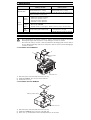
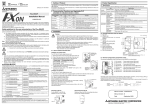
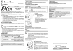
3.1 Installation of FX2N-ROM-E1
b )
a )
M e m o ry p ro te c t
s w itc h
X 1
X 3
IN
6 7 61 7
4 5 41 51
2 3 21 31
0 1 01 11
1
6 7 61 7
4 5 41 51
2 3 21 31
0T 1 0 1 1 1
4 1
O U 1
Y 1 M 4Y
C O
2 Y 1 3
1
Y
+
2 4
L
N
3
Y 2 Y
1
Y 0 Y
C O
7
Y 6 Y
5
Y M4 2 Y
7
C O
F X 2 N m a in u n it
1) Turn off the power of the PLC and remove the cover "a)".
2) Install FX2N-ROM-E1 "b)" to the port on the main unit.
3) Put back the cover "a)".
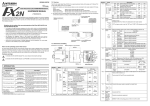
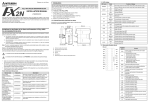
3.2 Installation of FX2NC-ROM-CE1
c )
b )
M e m o r y p r o te c t s w itc h
a )
F X 2 N C m a in u n it
1) Turn off the power of the PLC and remove the cover "a)".
2) Install FX2NC-ROM-CE1 "b)" to the port on the main unit.
3) Place cover "c)", included in the memory board product box, onto the PLC.
3.3 Operation
•
•
•
•
The program error may flash when used for the first time because the EEPROM (user program memory) is
not initialized. In the personal computer or FX-20P (off-line mode), transfer and write a program in that
status. In the FX-10P or FX-20P (online mode), execute all NOP write to erase the contents.
After writing a program, make sure to verify.
Set the memory protect switch to OFF before writing a program. During normal operation, it is recommended
to set it to ON to prevent erroneous write.
When installed in the FX 2N or FX2NC Series PLC version 3.00 or later, the EXTR (FNC 180) instruction and
the 16k-step EEPROM and clock function can be used.
If installed in the FX2N or FX2NC Series PLC earlier than version 3.00, only the 16k-step EEPROM and clock
function can be used.
4. Inverter Communication Function
• When handling the PLC or inverter, follow the notices indicated in each manual which is
included with the main unit in order to avoid electric shock, fire, a damage or an accident.
• Make sure to perform class D grounding of the ground terminal of communication equipment for
the PLC together with that of the PLC main unit. Ground the shield of a shielded cable at one
point on the PLC. Do not, however, ground at the same point as high voltage line. If grounding is
imperfect, effects of noise or surge induction takes place, and it may cause a communication
error or erroneous operation.
• The signal cables must not be laid near or bundled with the main circuit lines, high voltage power
cables or load carrying wires. Otherwise effects of noise or surge induction are likely to take
place, and it may cause a communication error or erroneous operation.
Keep a safe distance of more than 100mm (3.94") from these wires.
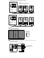
4.1 Outline of Functions and System Configuration
When using K10 to K13 of the EXTR (FNC 180) instruction, operation monitoring, control value write or
parameter monitoring and change in the A500/E500/S500 (with RS-485 communication function) Series
MITSUBISHI TRANSISTORIZED INVERTER can be performed.
The details of programming and setting can be found in the Programming Manual II, JY992D88101.
•
Total extension distance
PLC
FX2N
FX2NC
•
Using interface
FX2N-485-BD
Extension distance
Maximum 50m (164')
FX2N-CNV-BD + FX0N-485ADP
FX0N-485ADP
Maximum 500m (1640')
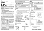
Connecting with one inverter
2) Inverter
1) PLC
FX2N,FX2NC
(version 3.00 or later)
S500 (with RS-485
communication function)
E500
PU (RS-485) connector
3) 10 BASE-T cable
A500
PU connector
RS-485 communication module
[FX2N]
. FX2N-485-BD
. FX0N-485ADP + FX2N-CNV-BD
[FX2NC]
. FX0N-485ADP
4) Twisted pair cable
A500
Optional connection
Termination resistors are
needed on both ends of 1)
and 2).
FR-A5NR
•
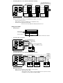
Connecting with two or more inverters (Maximum 8 inverters)
1) PLC
FX2N, FX2NC
(version 3.00 or later)
2) Inverter
S500 (with RS-485 communication function),
E500, A500 series PU (RS-485) connector
Station number 0
Inverter
Station number 1
Inverter
RS-485 communication module
Station number 7
Inverter
.....
[FX2N]
. FX2N-485-BD
. FX0N-485ADP + FX2N-CNV-BD
PU (RS-485)
connector
[FX2NC]
. FX0N-485ADP
PU (RS-485)
connector
PU (RS-485)
connector
Distribution
terminal
Terminal
resistor
Terminal
resistor
3) 10 BASE-T cable
2) Inverter
A500 + FR-A5NR (optional)
1) PLC
FX2N, FX2NC
(version 3.00 or later)
Station number 0
Inverter
Station number 1
Inverter
RS-485 communication module
Station number 7
Inverter
.....
[FX2N]
. FX2N-485-BD
. FX0N-485ADP + FX2N-CNV-BD
[FX2NC]
. FX0N-485ADP
FR-A5NR
Terminal
resistor
FR-A5NR
FR-A5NR
Terminal
resistor
3) Twisted pair cable
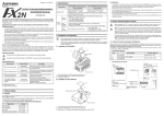
4.2 Wiring
Wiring for PU (RS-485) Connector
•
Pin layout of PU (RS-485) connector
Pin number
Signal name
1
SG
2
P5S
3
RDA
4
SDB
5
SDA
6
RDB
7
SG
8
P5S
Note
Viewing from front
face of inverter
(receptacle side)
Not to be used
j
c
Modular jack
Not to be used
Caution:
The pin number 2 and 8 are for the power supply for an operation panel or parameter unit. DO
NOT use when connecting two or more inverters.
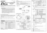
•
Connecting with one inverter
110Ω terminal resistor
Distribution
terminal
FX0N-485ADP FX2N-485-BD
RDA
RDA
5
5
RDB
RDB
4
4
SDA
SDA
3
3
SDB
SDB
6
6
24V DC LINK
SG
50mA
24+
24G
FG
Class D grounding
SG
10 BASE-T cable
1
1
54361
PLC
PU (RS-485) S S R R
S
connector
DDDD
G
ABAB
Inverter
54361
100Ω 1/4W terminal resistor
(prepared by the user)
•
Connecting with two or more inverters (Maximum 8 inverters)
100Ω 1/4W terminal resistor
(prepared by the user) attached to
the remotest inverter from PLC
110Ω terminal resistor
Distribution
terminal
FX0N-485ADP FX2N-485-BD
RDA
RDA
Distribution
terminal
5
5
5
5
5
5
RDB
RDB
4
4
4
4
4
4
SDA
SDA
3
3
3
3
3
3
SDB
SDB
6
6
6
6
6
6
1
1
1
1
1
24V DC LINK
50mA
SG
SG
PLC
24+
24G
FG
Class D grounding
•
Distribution
terminal
10 BASE-T
cable
54361
54361
PU (RS-485) S S R R
connector D D D D S
G
ABAB
Inverter
54361
PU (RS-485) S S R R
connector D D D D S
G
ABAB
Inverter
54361
1
54361
...
PU (RS-485) S S R R
connector D D D D S
G
ABAB
Inverter
54361
Applicable equipment
Use the connectors and cables for LAN (10 BASE-T) available on the market.
-
Connector: RJ45 connector
Cable: Cable conforming to EIA568 (such as 10 BASE-T cable)
Terminal resistor: On the PLC side, 110Ω
On the inverter side, 100Ω and 1/4W prepared by the user
Wiring for FR-A5NR
•
Terminal layout
Terminal block
screw size M3 (0.12")
SDA SDB RDA
RDB RDR
SG
B
A
C
Terminal symbol
Used to connect to PLC RS-485 communication module
•
Connecting with one inverter
110Ω terminal resistor
FX0N-485ADP FX2N-485-BD
RDA
RDA
RDB
RDB
SDA
SDA
SDB
SDB
24V DC LINK
50mA
SG
SG
24+
PLC
Twisted pair cable
(0.3mm2 or more)
A chip for connecting terminal
resistor
SS
S
G DD
AB
24G
FG
0.3mm2 or more
Class D grounding
•
RRR
DDD
ABR
FR-A5NR
Inverter
Connecting with two or more inverters (Maximum 8 inverters)
110Ω terminal resistor
2
Twisted pair cable (0.3mm or more)
FX0N-485ADP FX2N-485-BD
RDA
RDA
RDB
RDB
SDA
SDA
SDB
SDB
24V DC LINK
50mA
SG
SG
24+
PLC
Class D
grounding
SS
S DD
G
AB
24G
FG
Class D grounding
•
0.3mm2
or more
RRR
DDD
ABR
FR-A5NR
Inverter
SS
S DD
G
AB
A chip for
connecting
terminal
resistor
attached to
the remotest
inverter from
PLC
Class D grounding
RRR
DDD
ABR
FR-A5NR
Inverter
.....
SS
S DD
G
AB
RRR
DDD
ABR
FR-A5NR
Inverter
Applicable equipment
-
Cable: Use the twisted pair cables (0.3mm2 or more, 3 pairs)
Terminal resistor : On the PLC side, 110Ω
On the inverter side, a chip for connecting terminal resistor only to the remotest
FR-A5NR from the PLC (between RDB and RDR)
Manual number : JY997D00401
Manual revision : A
Date
: JULY 2001
HEAD OFFICE : MITSUBISHI DENKI BLDG MARUNOUTI TOKYO 100-8310
HIMEJI WORKS : 840, CHIYODA CHO, HIMEJI, JAPAN
TELEX : J24532 CABLE MELCO TOKYO