1
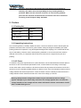
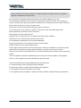
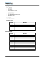
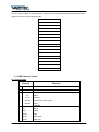
User manual
Easy Move XS
HP Wash
Table of content
1.
Safety instructions ........................................................................................................................3
1.1.
2.
3.
4.
5.
Preface ........................................................................................................................................4
2.1.
Packing list ..........................................................................................................................4
2.2.
Unpacking instructions .........................................................................................................4
2.3.
AC Power ............................................................................................................................4
2.4.
Safety instructions ...............................................................................................................5
Introduction ..................................................................................................................................6
3.1.
Features ..............................................................................................................................6
3.2.
DMX Channels ....................................................................................................................6
Set up ..........................................................................................................................................7
4.1.
Fuse replacement ................................................................................................................7
4.2.
Fixture linking ......................................................................................................................7
4.3.
3-Pin to 5-Pin conversion chart ............................................................................................7
4.4.
Master/Slave fixture linking ..................................................................................................8
4.5.
Orientation ...........................................................................................................................8
Operating instructions ..................................................................................................................8
5.1.
Navigating the control panel .................................................................................................8
5.2.
Menu map ...........................................................................................................................8
5.3.
User configurations ..............................................................................................................8
5.3.1.
Setting Maximum Pan Angles.......................................................................................8
5.3.2.
Setting Maximum Tilt Angles ........................................................................................8
5.4.
6.
FOR SAFE AND EFFICIENT OPERATION ..........................................................................3
One-in-built Program Mode (continued)................................................................................9
5.4.1.
Setting Reversed or Normal Pan ..................................................................................9
5.4.2.
Setting Reversed or Normal Tilt....................................................................................9
5.4.3.
Setting Reversed or Normal LED Display .....................................................................9
Modes..........................................................................................................................................9
6.1.
Auto Run Mode....................................................................................................................9
6.1.1.
7.
Choosing Auto Run Sub-modes ...................................................................................9
6.2.
Sound Activated Mode .........................................................................................................9
6.3.
Slave Mode ....................................................................................................................... 10
6.4.
Service Modes ................................................................................................................... 10
6.5.
DMX Modes....................................................................................................................... 10
6.6.
Color Options .................................................................................................................... 11
6.7.
DMX channel Values ......................................................................................................... 11
Technical data ........................................................................................................................... 13
2 / 14
1. Safety instructions
This device is suitable for indoor use only.
All modifications to the device will void the warranty.
Repairs are to carry out by skilled personnel only.
Use only fuses of the same type and original parts as spare parts.
Protect the unit from rain and humidity to avoid fire and electric shocks.
Make sure to unplug the power supply before opening the housing.
1.1. FOR SAFE AND EFFICIENT OPERATION
Be careful with heat and extreme temperature
Avoid exposing it to direct rays of the sun or near a heating appliance.
Not put it in a temperature bellow 41°F /5°C, or exceeding 95°F /35°C.
Keep away from humidity, water and dust
Do not place the set in a location with high humidity or lots of dust.
Containers with water should not be placed on the set.
Keep away from sources of hum and noise
Such as transformer motor, tuner, TV set and amplifier.
To avoid placing on un-stable location
Select a level and stable location to avoid vibration.
Do not use chemicals or volatile liquids for cleaning
Use a clean dry cloth to wipe off the dust, or a wet soft cloth for stubborn dirt.
If out of work, contact sales agency immediately
Any troubles arose, remove the power plug soon, and contact with an engineer for repairing,
do not open the cabinet by yourself, it might result a danger of electric shock.
Take care with the power cable
Never pull the power cable to remove the plug from the receptacle, be sure
to hold the plug. When not using the device for an extended period of time, be sure to
disconnect the plug from the receptacle.
3 / 14
Important:
Damages caused by the disregard of this user manual are not subject to
warranty. The dealer will not accept liability for any resulting defects or
problems. Make sure the electrical connection is carried out by qualified
personnel. All electrical and mechanical connections have to be carried out
according to the European safety standards.
2. Preface
2.1. Packing list
Product name
Quantity
Flat Par Light
1 pcs
Power -line
1 pcs
User Manual
1 pcs
2.2. Unpacking instructions
Once receiving a fixture, carefully unpack the carton, check the contents to ensure that all parts are
presented, and have been received in a good condition. Notify the shipper immediately and retain
packing material for inspection if any parts appear damaged from shipping or the carton itself shows,
sign of mishandling. Save the carton and all packing materials. In the event that a fixture must be
returned to the factory, it is important that the fixture be returned in the original factory box and
packing.
2.3. AC Power
To determine the power requirements for a particular fixture, see the label affixed to the back plate of
the fixture or refer to the fixtures specifications chart. A fixture listed current rating is its average
current draw under normal conditions. All fixtures must be directly powered off a switched circuit and
cannot be run off a rheostat (variable resistor) or dimmer circuit, even if the rheostat or dimmer source
voltage matches the fixtures requirement. Check the fixture or device carefully to make sure that if a
voltage selection switch exists that it sets to the correct line voltage you will use.
Warning! Verify that the voltage select switch on your unit matches the line voltage
applied. Damage to your fixture may result if the line voltage applied does not match the
voltage indicated on the voltage selector switch. All fixtures must be connected to circuits
with a suitable Earth ground.
4 / 14
2.4. Safety instructions
Please read these instructions carefully, it includes important information about the installation,
usage and maintenance of this product.
Be sure that the local power outlet matches that of the required voltage for your unit.
Do not attempt to operate this unit if the power cord has been frayed or broken. Do not attempt to
remove or break off the ground prong from the electrical cord. This prong is used to reduce the risk of
electrical shock and fire in case of an internal short.
Disconnect from main power before making any type of connection.
Do not remove the cover under any conditions. There are no user serviceable parts inside.
Never operate this unit when its cover is removed.
Never plug this unit into a dimmer pack.
Always be sure to mount this unit in an area that will allow proper ventilation.
Allow about 6 inch (15cm) between this device and a wall.
Do not attempt to operate this unit, if it becomes damaged.
During long periods of non-use, disconnect the unit's main power.
Always mount this unit in safe and stable matter.
Power-supply cords should be routed so that they are not likely to be walked on or pinched by items
placed upon or against them, paying particular attention to the point they exit from the unit.
Cleaning -The fixture should be cleaned only as recommended by the manufacturer. See Cleaning for
details.
Heat -The appliance should be situated away from heat sources such as radiators, heat registers,
stoves, or other appliances (including amplifiers) that produce heat.
The fixture should be serviced by qualified service personnel when:
A. The power-supply cord or the plug has been damaged.
B. Objects have fallen, or liquid has been spilling to the appliance.
C. The appliance has been exposed to rain or water.
D. The appliance does not appear to operate normally or exhibits a marked change in performance.
5 / 14
3. Introduction
3.1. Features
-
Multi-Colors
-
Color Strobe
-
Electronic Dimming 0-100%
-
Built in Microphone
-
DMX-512 Control
-
Auto/ Master & Slave synchronization
-
Multi-channel mode
3.2. DMX Channels
In 5 channel mode
Channel
Function
1
PAN
2
TILT
3
DIMMER & STROBE
4
COLOR
5
BLANK
In 12 channel mode
Channel
Function
1
PAN
2
PAN FINE
3
TILT
4
TILT FINE
5
PAN/TILT SPEED
6
DIMMER & STROBE
7
RED
8
GREEN
9
BLUE
10
COLOR
11
COLOR SPEED
12
MOVEMENT(AUTO & SOUND EFFECT)
6 / 14
4. Set up
Disconnect the power cord before replacing a fuse and always replace with the same type fuse.
Power Supply: Before plugging your unit in, be sure the source voltage in your area matches the
required voltage. The Light is available in a 110v to 250v version. Because line voltage may vary from
venue to venue, you should be sure your unit voltage matches the wall outlet voltage before
attempting to operate you fixture.
4.1. Fuse replacement
With a flat head screwdriver wedge the fuse hold out of its housing. Remove the damaged fuse from
its holder and replace with exact same type fuse. Insert the fuse holder back in its place and reconnect
power.
4.2. Fixture linking
You will need a serial data link to run light show of one or more fixtures using a DMX-512 controller or
to run synchronized on two or more fixtures set to a master/slave operating mode. The combined
number of channels required by all the fixtures on a serial data link determines the number of fixtures
the data link can support.
Maximum recommended serial data link distance: 500 meters (1640ft).
Maximum recommended number of fixtures on a serial data link: 32 fixtures.
Data cabling
To link fixtures together you must obtain data cables. If you choose to create your own cable please
use data-grade cables that can carry a high quality signal and are less prone to electromagnetic
interference.
4.3. 3-Pin to 5-Pin conversion chart
Note! If you use a controller with a 5 pin DMX output connector. you will need to use a 5pin to 3 pin
CHAUVET Model No: DMX 5M or DMX 5F
The chart below details a proper cable conversion:
7 / 14
4.4. Master/Slave fixture linking
1. Connect the (male) 3 pin connector side of the DMX cable to the output (female) 3pin
connector of the first fixture.
2. Connect the end of the cable coming from the first fixture which will have a (female) 3 pin
connector to the input connector of the next fixture consisting of a (male) 3 pin connector.
Then, proceed to connect from the output as stated above to the input of the following fixture
and so on.
4.5. Orientation
This fixture may be mounted in any position provided there is adequate room for ventilation.
5. Operating instructions
5.1. Navigating the control panel
Access control panel functions using the four panel buttons located directly under the Display.
5.2. Menu map
Six distinct operating modes, many with sub-modes, are supported by the unit. To selected use the
“MODE/ESC” button to enter the menu. “UP” and “DOWN” button choose from values available with
the “ENTER” button confirming any selection. After a few seconds, the LED Display will back during
operation until another button is pressed.
In –built Program Mode
5.3. User configurations
5.3.1. Setting Maximum Pan Angles
To select, use the “MODE/ESC” button and choose “PA18”, “PA36”,or “PA54”. “UP” and “DOWN”
buttons cycle between all available Pan Angles. Press the “ENTER” button to confirm the chosen
selection.
LED Display
Maximum Pan
PA18
180º
PA36
360º
PA54
540º
5.3.2. Setting Maximum Tilt Angles
To select, use the “MODE/ESC” button and choose “t.9” or “t.18” “UP” and “DOWN” buttons cycle
between all available Tilt Angles. Press the “ENTER” button to confirm the chosen selection.
LED Display
Maximum Pan
t.9
90º
t.18
180º
8 / 14
5.4. One-in-built Program Mode (continued)
As the unit can be mounted hung under earth trussing, or can sit equally well on a flat surface, pan, tilt
and LED display settings can be reserved to provide correct coverage and ease of use.
5.4.1. Setting Reversed or Normal Pan
To select, use the “MODE/ESC” button and choose “Pan”(normal) or “r Pan” (reversed). “UP” and
“DOWN” buttons cycle between the two settings. Press the “ENTER” button to confirm the chosen
selection
5.4.2. Setting Reversed or Normal Tilt
To select, use the “MODE/ESC” button and choose “t.L” (normal) or “rt.l”(reversed).“UP” and “DOWN”
buttons cycle between the two settings. Press the “ENTER” button to confirm the chosen selection
5.4.3. Setting Reversed or Normal LED Display
To select, use the “MODE/ESC” button and choose “d.s”(normal) or “rd.s”(reversed). “UP” and
“DOWN” buttons cycle between the two settings. Press the “ENTER” button to confirm the chosen
selection
6. Modes
6.1. Auto Run Mode
One of two Auto Run Sub-modes can be selected with a choice of preset speeds .This mode enables
the unit to act as a Master to other Slave units
6.1.1. Choosing Auto Run Sub-modes
To select, use the “MODE/ESC” button to show “NAFA” or “NASL”. “UP” and “DOWN” buttons change
between the two initial options. With the appropriated option selected, use “ENTER” to confirm and the
LED Display with change to: “Fast” (fast) or “SloU” (slow). The unit will then run at the chosen speed
Initial LED Display
Second LED Display
Sub-mode
NAFA
Fast
Fast Auto Run
NAFL
SloU
Slow Auto Run
6.2. Sound Activated Mode
The unit responds to sounds picked up by the unit in microphone to create a light show . Each sound
picked up makes changes to color shown and position of the effects. This mode enables the unit to act
a Master to other Slave units
Choosing Sound Activated
To select, use the “MODE/ESC” button and choose “NStS”. When the “ENTER” button is pressed the
LED Display changes to “SrUn” and the unit enters Sound Activated Mode.
Initial LED Display
Second LED Display
Sub-mode
NStS
SrUn
Sound Activated
9 / 14
6.3. Slave Mode
Up-to 32 units can be daisy chained together with one single unit acting as Master and all other linked
units as Slaves. Slave units will all run in synch with the master unit without the need for an additional
controller. Connections can be made using standard DMX control cables with Master unit running in
Auto Run or Sound Activated Modes an placed at the start of the chain
Choosing Slave Mode
To select, use the “MODE/ESC” button and choose “SLAu”. When the “ENTER” button is pressed the
LED display changes to “Son” and the unit will be slaved to control signals coming from a Master unit
6.4. Service Modes
After major configuration changes it may be necessary to reboot or reset the unit.
Resetting the Unit
To select, use the “MODE/ESC” button and choose “rEST”(restore). Press “ENTER” to confirm. The
unit powers itself down and then on again for a few seconds. During this time the LED display will
scroll “rEST” from left to right, after which normal operation recommences.
Restoring factory defaults
To select, use the “MODE/ESC” button and choose “LoAD”(load). Press “ENTER” to confirm. The LED
display will change to “d001” to confirm a factory reset has been completed
Powering the unit initially
During the warm up the unit will auto test itself for a few seconds. During this time the led
display will scroll “rEST” from left to right .The unit then commences operation normall
6.5. DMX Modes
The unit supports 5 and 12 channel DMX Sub-modes frim a standard desk. When a suitable DMX
connection is made, the “decimal point” in “d.001” will flash.
Setting DMX Addresses
Use the “MODE/ESC” button to display “d001”, “UP” and “DOWN” buttons allows individual DMX
addresses to be set from “d001” to “d512”
Choosing between DMX Sub-modes
The LED display shows the chosen control mode when the “MODE” button is pressed. Use “UP” and
“DOWN” buttons to choose the appropriated DMX control Mode
LED Display
DMX Sub-mode
5CH
5Channel
12CH
12channel
10 / 14
6.6. Color Options
The Unit offers a range of 16 preset colors. These can be individually selected with DMX control and
feature in Auto Run Sound Active modes.
Color Preset
White
Red
Dark Green
Dark Blue
Light Blue
Magenta
Yellow
Purple
Orange
Light Green
Pink
Ochre
Gold
Crimson
Violet
Dark Purple
6.7. DMX channel Values
In 5 channel mode
Channel
Function
1
0-255
PAN
2
0-255
TILT
DIMMER & STROBE
0-7
3
8-134
blank
Dimmer
135-239
Strobe from 0Hz to 40Hz
240-255
Open
COLOR
4
0-7
Blank
8-21
White
22-34
Red
35-49
Dark green
50-63
Dark blue
11 / 14
5
64-77
Light blue
78-91
Magenta
92-105
Yellow
106-119
Purple
120-133
Orange
134-147
Light green
148-161
Pink
162-175
Ochre
176-189
Gold
190-203
Crimson
204-217
Violet
218-231
Dark Purple
232-255
Color Change
0-255
BLANK
In 12 channel mode
Channel
Function
1
0-255
PAN
2
0-255
PAN FINE
3
0-255
TILT
4
0-255
TILT FINE
5
0-255
PAN/TILT SPEED
From Fast to Slow
DIMMER & STROBE
0-7
Blank
8-134
Dimmer
135-239
Strobe from 0Hz to 40Hz
240-255
Open
7
0-255
RED
8
0-255
GREEN
9
0-255
BLUE
6
COLOR
10
0-7
Blank
8-21
White
22-34
Red
35-49
Dark Green
50-63
Dark Blue
64-77
Light Blue
78-91
Magenta
92-105
Yellow
12 / 14
11
106-119
Purple
120-134
Orange
135-147
Light Green
148-161
Pink
162-175
Ochre
176-189
Gold
190-203
Crimson
204-217
Violet
218-231
Dark Purple
232-255
Color Change
0-255
COLOR SPEED
MOVEMENT(AUTO & SOUND EFFECT)
12
0-7
Blank
8-22
Auto 1
23-37
Auto 2
38-53
Auto 3
54-67
Auto 4
68-82
Auto 5
83-97
Auto 6
98-112
Auto 7
113-127
Auto 8
128-142
Sound 1
143-157
Sound 2
158-172
Sound 3
173-187
Sound 4
188-202
Sound 5
203-217
Sound 6
218-232
Sound 7
233-255
Sound 8
7. Technical data
Model number
HP Wash 18 x 3W
Voltage
230V/50Hz
LED
18x3w LED
Dimensions
225mm*225mm*270mm
Net Weight
4.2Kg
Power consumption
80W max
Max Pan Angle
540°
Max Tilt Angle
180°
13 / 14
Importer:
B & K Braun GmbH
Industriestraße 1
D-76307 Karlsbad
www.bkbraun.com
info@bkbraun.com
14 / 14