1
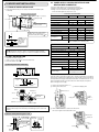
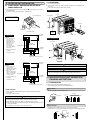
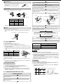
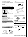
ADVANCED AND EVER ADVANCING
VG79A008H02
SPLIT-TYPE AIR CONDITIONERS
Models
MS12/15/17TN
MSH12/15TN
Series
[FLARE CONNECTION TYPE]
CAUTION
1. THE FOLLOWING SHOULD ALWAYS BE
OBSERVED FOR SAFETY
•
•
•
•
INSTALLATION MANUAL
■ Ground the unit.
Do not connect the ground to a gas pipe, water pipe, lightning rod or
telephone ground. Defective grounding could cause an electric shock.
Please report to your supply authority or obtain their consent before connecting
this equipment to the power supply system.
Be sure to read “THE FOLLOWING SHOULD ALWAYS BE OBSERVED FOR
SAFETY” before installing the air conditioner.
Be sure to observe the cautions specified here as they include important items
related to safety.
The indications and meanings are as follows.
■ Do not install the unit in a place where an inflammable gas leaks.
If gas leak and accumulate in the area surrounding the unit, it could cause an
explosion.
■ Install a ground leakage breaker depending on the installation place
(Where it is humid).
If a ground leakage breaker is not installed, it could cause an electric shock.
■ Perform the drainage/piping work securely according to the installation
manual.
If there is a defect in the drainage/piping work, water could drop from the unit
and household goods could be wet and damaged.
WARNING
Could lead to death, serious injury, etc.
CAUTION
Could lead to serious injury in particular environments when operated incorrectly.
•
After reading this manual, be sure to keep it together with the OPERATING
INSTRUCTIONS in a handy place on the customer’s site.
WARNING
■ Do not install the unit by yourself (customer).
Incomplete installation could cause injury due to fire, electric shock, the unit
falling or leakage of water. Consult the dealer from whom you purchased the
unit or special installer.
■ Install the unit securely in a place which can bear the weight of the unit.
When installed in an insufficient strong place, the unit could fall causing injury.
■ Use the indoor/outdoor unit connecting wire that meets the Standards to
connect the indoor and outdoor units and fix the wire to the terminal
block securely so that no external force is conveyed to the connecting
section of the terminal block.
Incomplete connection or fixing of the wire could result in a fire.
■ Do not use intermediate connection of the power cord or the extension
cord and do not connect many devices to one AC outlet.
It could cause a fire or an electric shock due to defective contact, defective
insulation, exceeding the permissible current, etc.
■ Check that the refrigerant gas do not leak after installation has completed.
■ Perform the installation securely referring to the installation manual.
Incomplete installation could cause a personal injury due to fire, electric
shock, the unit falling or leakage of water.
■ Perform electrical work according to the installation manual and be sure
to use an exclusive circuit.
If the capacity of the power circuit is insufficient or there is incomplete
electrical work, it could result in a fire or an electric shock.
2. SELECTING THE INSTALLATION LOCATION
2-1 INDOOR UNIT
•
•
•
•
•
•
•
•
•
2-2 OUTDOOR UNIT
•
•
•
•
•
•
•
•
•
■ Be sure to cut off the main power in case of setting up the indoor
electronic control P.C. board or wiring works.
It could cause an electric shock.
Where it is not exposed to strong wind.
Where airflow is good and dustless.
Where it is not exposed to rain and direct sunshine.
Where neighbours are not annoyed by operation sound or hot air.
Where rigid wall or support is available to prevent the increase of operation sound
or vibration.
Where there is no risk of combustible gas leakage.
When installing the unit at a high level, be sure to fix the unit legs.
Where it is at least 10 ft. away from the antenna of TV set or radio. (Otherwise,
images would be disturbed or noise would be generated.)
Install the unit horizontally.
CAUTION
■ Attach the electrical cover to the indoor unit and the service panel to the
outdoor unit securely.
If the electrical cover in the indoor unit and/or the service panel in the outdoor
unit are not attached securely, it could result in a fire or an electric shock due
to dust, water, etc.
■ Be sure to use the part provided or specified parts for the installation
work.
The use of defective parts could cause an injury due to a fire, an electric
shock, the unit falling, leakage of water, etc.
Where airflow is not blocked.
Where cool air spreads over the entire room.
Maximum refrigerant piping length between indoor unit and outdoor unit is 49 ft.
and the difference of height of both units is 25 ft. maximum.
Rigid wall without vibration.
Where it is not exposed to direct sunshine.
Where easily drained.
At a distance 3 ft. or more away from your TV and radio (to prevent picture from
being distorted or noise from being generated).
In a place as far away as possible from fluorescent and incandescent lights (so
the infrared remote control can operate the air conditioner normally).
Where the air filter can be removed and replaced easily.
Avoid the following places for installation where air conditioner trouble is liable to
occur.
Where there is too much machine oil.
Salty environment as seaside areas.
Hot-spring areas.
Where sulfide gas exists.
Other special atmospheric areas.
•
•
•
•
•
2-3 WIRELESS REMOTE CONTROLLER MOUNTING
•
•
Place of mounting
• Where it is easy to operate and easily visible.
• Where children can not touch.
Mounting
Select a position about 4 ft. above the floor, check that signals from the remote
controller are surely received by the indoor unit from that position (‘beep’ or ‘beepbeep’ receiving tone sounds). After that, attach remote controller mounting
hardware 3 to a pillar or wall and set the wireless remote controller 6.
In rooms where inverter type fluorescent lamps are used, the signal from the
wireless remote controller may not be received.
PIPING PREPARATION
3. INSTALLATION DIAGRAM & ACCESSORIES
1 Table below shows the specifications of pipes commercially available.
2 Ensure that the 2 refrigerant pipes are insulated to prevent condensation.
3 Refrigerant pipe bending radius must be 4 in. or more.
FLARED CONNECTIONS
•
•
•
This unit has flared connections on both indoor and outdoor sides.
Remove the valve cover of the outdoor unit, then connect the pipe.
Refrigerant pipes are used to connect the indoor and outdoor units.
Outside diameter Minimum wall thickness Insulation thickness
Pipe
inch
Limits
Pipe length
49 ft. max.
Height difference
25 ft. max.
No. of bends
•
For liquid
12 type
For
gas 15, 17 type
10 max.
Refrigerant adjustment ... If pipe length exceeds 25 ft., additional refrigerant
(R-22) charge is required.
(The outdoor unit is charged with refrigerant for pipe length up to 25 ft..)
Up to 25 ft.
Pipe length
be added
1/4
0.0265
5/16
1/2
0.0285
5/16
5/8
0.0315
5/16
CAUTION
(Refer to the table below.)
0.53 oz each 5 ft.
MSH type
2.68 oz each 5 ft.
Heat resisting
foam plastic
Specific
gravity 0.045
Be sure to use the insulation of specified thickness. Excessive thickness may
cause incorrect installation of the indoor unit and lack of thickness may cause
dew drippage.
Additional charge is required.
MS type
Insulation
material
Minimum wall thickness is UL1995 33’s reference.
Refrigerant pipes of 10, 16, 23, 33 and 49 ft. are available as optional items.
No additional charge is required.
Exceeding 25 ft.
Refrigerant to
•
•
inch
Decide the installation position using mark on the installation plate
indicating the indoor unit size as reference.
ACCESSORIES
Check the following parts before installation.
1
Installation plate
2
Installation plate fixing screw 4 × 25 mm
6
3
Remote controller mounting hardware
1
1
Fixing screw for 3 3.5 × 16 mm (Black)
2
Battery (AAA) for remote controller
2
6
Wireless remote controller
1
7
Felt tape (Used for left or left-rear piping)
1
10 in
. or m
ore
2
PART TO BE PROVIDED AT YOUR SITE
Be careful the
drain hose is not
raised.
3-3/16 in. or more
4
5
1
10 in
. or m
ore
Optional extension pipe
Indoor/outdoor unit connecting wire
1
B
Extension pipe
1
C
Wall hole sleeve
1
D
Wall hole cover
1
E
Pipe fixing band (The quantity depends
on the pipe length.)
2 to 5
F
Fixing screw for E 4 × 20 mm (The
quantity depends on the pipe length.)
2 to 5
G
Piping tape
1
H
Putty
1
I
Drain hose (or soft PVC. hose,
19/32 in. inner dia. or hard PVC pipe VP16)
1
Refrigeration oil
1
J
MU12TN and MUH12TN
D
1-3/6 in. or more
A
7
C
H
Downward
B
4 in. or more
A
Left-rear
Lock the catch.
E
G
4
F
Separate the 2 connecting pipes and
apply insulation individually.
MU15/17TN and MUH15TN
4 in. or more
Left
Rear
3
6
5
Piping can be directed towards rear,
right, downward, left or left-rear
directions.
Front
Rear side
Right
4 in. or more
4 in. or more
A
5/16 in. thickness thermal insulation
plastic.
4 in. or more
4 in. or more
When the piping is to be attached to a
wall containing metals (tin plated) or
metal netting, use a chemically treated
wooden piece 13/16 in. or thicker
between the wall and the piping or
wrap 7 to 8 turns of insulation vinyl
tape around the piping.
I
I
16 in. or more
14 in. or more
Note:
If clearance behind the
outdoor unit is only
15-3/4 or 20 in., side A
must be fully opened.
20 in. or more
14 in. or more
33-7/16
3/4
30-3/4
(Unit: inch)
Air outlet
3/4
Air outlet
3/8
11-7/16
10-1/16
11-7/32
4-3/8 ×
13/16 slot
12-7/32
Note:
If clearance behind the
outdoor unit is only
15-3/4 or 20 in., side A
must be fully opened.
19-11/16
19-11/16
4-3/8 × 13/16 slot
Units should be installed by licensed contractor according to local code requirement.
4-3 POWER SUPPLY AND INDOOR/OUTDOOR CONNECTING WIRE CONNECTION
4. INDOOR UNIT INSTALLATION
4-1 FIXING OF INSTALLATION PLATE
•
Find a structural material (such as a stud) in the wall and fix installation plate
horizontally.
•
•
•
Power should be taken from an exclusive branched circuit.
Wiring work should be based on applicable technical standards.
Wiring connections should be made following the diagram.
Screws should be tightened so they won’t loosen.
Tie a piece of thread to the hole.
3-3/16 in. or more
ELECTRICAL SPECIFICATIONS
Fixing screw 2 4 × 25 (6 pieces)
MODEL
MS12TN
Installation plate 1
10 in. or more
10 in. or
more
Power supply (V, PHASE, Hz)
Secure the arrow marked hole
as much as possible.
115, 1, 60
115, 1, 60
115, 1, 60
0.6
0.6
0.7
Fan motor (F.L.A)
0.43
0.43
0.51
OUTDOOR UNIT
208/230, 1, 60
208/230, 1, 60
208/230, 1, 60
Max. Fuse size (time delay) (A)
15
20
20
Min. Circuit Ampacity
12
14
15
0.42
0.52
0.52
(R.L.A)
9.0
10.0
11.0
(L.R.A)
29.0
35.0
38.0
Fan motor (F.L.A)
Compressor
Fix the
installation plate
1 so that the
plumb string
stays in this
range.
MS17TN
Min. Circuit Ampacity
Power supply (V, PHASE, Hz)
Horizontal level can be easily obtained by
handing a piece of weight in a piece of
mark.
thread and matching with a triangle
MS15TN
INDOOR UNIT
Indoor unit-Remote controller : (Wireless)
Indoor unit-Outdoor unit : DC12V (Polar)
Control voltage
ELECTRICAL SPECIFICATIONS
MODEL
MSH12TN
MSH15TN
INDOOR UNIT
When bolts recessed in the concrete wall are to be utilized, secure the installation
plate 1 using 7/16 in. × 13/16 in. · 7/16 in. × 1 in. oval hole (17-3/4 in. mm pitch).
If the recessed bolt is too long, change it for a shorter one available in the market.
Power supply (V, PHASE, Hz)
115, 1, 60
115, 1, 60
Min. Circuit Ampacity
0.6
0.6
Fan motor (F.L.A)
0.43
0.43
4-2 WALL HOLE DRILLING
OUTDOOR UNIT
1 Determine the wall hole position.
2 Drill a 3 in. hole so that outside can be lower than inside.
3 Insert the wall hole sleeve C.
Power supply (V, PHASE, Hz)
Positioning of the holes on the wall
208/230, 1, 60
15
20
Min. Circuit Ampacity
14
14
Fan motor (F.L.A)
Compressor
0.42
0.52
(R.L.A)
10.0
10.0
(L.R.A)
35.0
35.0
Indoor unit-Remote controller : (Wireless)
Indoor unit-Outdoor unit : DC12V (Polar)
Control voltage
4 in.
3-3/16 in.
Insert the
scale.
3-3/16 in.
Center of 3 in.
diameter.
Align scale with the line.
Note:
If the indoor unit is powered from outdoor unit, a separate circuit breaker is not required
but a disconnect switch may be required by local code. If the indoor unit is powered from
an independent power supply, a dedicated circuit breaker or maximum fuse size of 15 A
must be installed for the indoor unit, and a disconnect switch may also be required.
(Refer to the figures on the right.)
1 Remove the front panel (Refer to 7-1)
2 Remove the electrical cover
Wall hole
208/230, 1, 60
Max. Fuse size (time delay) (A)
3 Remove the display panel
Electrical cover
Wall thickness
3 in. dia.
One scale
Cut with 1 extra
scale length.
Display panel
Grounding
terminal
(Indoor side)
(Wall hole cross section)
Wall hole sleeve C
Be sure to use wall hole sleeve C to prevent the outdoor connecting wires from
contacting with metal part in the wall and to prevent damage by rat in case the wall
is hollow.
4 Fix the conduit connector to conduit cover with lock nut,
then secure it against electrical box with screws.
Wall hole sealing and fixing pipe to wall
Electrical box
Wall hole cover D
Seal the wall hole
gap with putty H.
Cut off the
extra length.
Conduit cover
Pipe fixing
band E
Fix the pipe to wall with
pipe fixing band E.
Connector
Conduit
Lock nut
Indoor unit
Wall hole
sleeve C
Fixing screw F
5-2 GROUNDING
5. OUTDOOR UNIT INSTALLATION
5-1 POWER SUPPLY AND INDOOR AND OUTDOOR
WIRE CONNECTION
•
•
Connect the indoor/outdoor unit connecting wire A from the indoor unit correctly on
the terminal block.
For future servicing, give extra length to connecting wire.
•
•
•
Remove the service panel.
Fix the conduit connector to conduit cover with lock nut then secure it against unit
with screw.
Leave some slack in wires to allow easier servicing.
MU12TN and MUH12TN
Lock nut
Service panel
Loosen terminal screw.
Connect wires to the matching
numbers of terminals.
Connector
Lead wire
Terminal block
<Connection details>
MU12/15/17TN
Grounding
terminal
Grounding
terminal
INDOOR UNIT
Terminal block
Remark:
∗ Indoor unit can also be
powered from an
independent power
supply [Max. Fuse size
(time delay) : 15 A].
In this case these
indoor/outdoor
connecting wires for
indoor power supply are
not necessary.
∗∗ A disconnect switch may
be required.
Check the local code.
Conduit cover
2 1 N L1
MU15/17TN and MUH15TN
Disconnect switch ∗∗
Lock nut
Service panel
115V AC ∗
1phase, 60Hz
DC12 V (Polar)
Grounding
terminal
Terminal
block 1
2 1 N L1 L1 N L2
Connector
Terminal block 2
OUTDOOR UNIT
Ground
Power supply
208/230V AC, 1phase 3wires, 60Hz
Grounding
terminal
MUH12/15TN
Remark:
∗ Indoor unit can also be
powered from an
independent power supply
[Max. Fuse size (time
delay) : 15 A].
In this case these indoor/
outdoor connecting wires
for indoor power supply
are not necessary.
∗∗ A disconnect switch may
be required.
Check the local code.
Grounding
terminal
INDOOR UNIT
Terminal block
CAUTION
3 1 N L1
Use care so as connecting wires do not contact pipes.
Disconnect switch ∗∗
WARNING
115V AC ∗
1phase, 60Hz
DC12 V (Polar)
Be sure to attach the service panel of the outdoor unit securely. If it is not attached
correctly, it could result in a fire or an electric shock due to dust, water, etc.
Grounding
terminal
Terminal
block 1
6. INDOOR/OUTDOOR UNIT CONNECTION
FINISHING AND TEST RUN
3 1 N L1 L1 N L2
Terminal block 2
OUTDOOR UNIT
Ground
Power supply
208/230V AC, 1phase 3wires, 60Hz
CONNECTING WIRES
• Wire to be AWG22 double insulated, 300 V insulation. Equal to Belden 9407
(for 12 V DC).
• Use copper conductors only.
6-1 FLARING WORK
•
Main cause of gas leakage is defect in flaring work.
Perform flaring work correctly in the following procedure.
1 Pipe cutting
• Cut the copper pipe correctly with pipe cutter.
No good
Copper pipe
CAUTION
•
•
•
•
•
Conduit
cover
Be careful not to make mis-wiring.
Firmly tighten the terminal screws to prevent them from loosening.
After tightening, pull the wires lightly to confirm that they do not move.
If the connecting wire is incorrectly connected to the terminal block, the unit does
not operate normally.
If a ground is incorrect, it may cause an electric shock.
Good
90°
Tilted
Uneven Burred
2 Burrs removal
• Completely remove all burrs from the cut cross section of the pipe.
• Put the end of the copper pipe downward to prevent burrs from dropping in the pipe.
Burr
Copper pipe
Spare
reamer
Pipe
cutter
CAUTION
•
•
•
•
•
AIR INTAKE
GRILLE
ELECTRICAL COVER
Be careful not to make mis-wiring.
Firmly tighten the terminal screws to prevent them from loosening.
After tightening, pull the wires lightly to confirm that they do not move.
If the connecting wire is incorrectly connected to the terminal block, the unit does
not operate normally.
If a ground is incorrect, it may cause an electric shock.
4-4 AUTO RESTART FUNCTION
•
•
Fixing screws
Indoor and outdoor connecting wire A
WARNING
•
•
Use the indoor/outdoor unit connecting wire that meets the Standards to connect
the indoor and outdoor units and fix the wire to the terminal block securely so that
no external force is conveyed to the connecting section of the terminal block.
Incomplete connection or fixing of the wire could result in a fire.
Attach the electrical cover securely. If it is attached incorrectly, it could result in a
fire or an electric shock due to dust, water, etc.
Loosen terminal screw.
Connect wires to the matching numbers
of terminals.
5/8 in.
Terminal block
Lead wire
<Connection details>
MS12/15/17TN
Remark:
∗ Indoor unit can also be
powered from an
independent power supply
[Max. Fuse size (time
delay) : 15 A].
In this case these indoor/
outdoor connecting wires
for indoor power supply
are not necessary.
∗∗ A disconnect switch may
be required.
Check the local code.
Grounding
terminal
INDOOR UNIT
2 1 N L1
Disconnect switch ∗∗
115V AC ∗
1phase, 60Hz
DC12 V (Polar)
Operation
1 If the power of the indoor unit (115V AC) has been cut, the operation settings
remain.
Remark:
When indoor and outdoor unit are powered in separate circuit even if the power of the
outdoor unit (208/230V AC) is cut auto restart function doesn’t work.
2 When three minutes have passed after power was restored, the unit will restart
automatically according to the memory.
Notes:
• The operation settings are memorized when 10 seconds have passed after the
remote controller was operated.
• If the main power is turned off or a power failure occurs while AUTO START/STOP
timer is active, the timer setting is cancelled. As these models are equipped with the
auto restart function, the air conditioner should start operating at the same time that a
power has restored.
• If the unit has been off with the remote controller before power failure, the auto
restart function does not work as the power button of the remote controller is off.
• To prevent breaker off due to the rush of starting current, systematize other home
appliances not to turn on at the same time.
4-5 PIPE FORMING
•
•
•
•
•
Terminal block
When the units of these models are shipped from the factory, auto restart function is
set to ON. If you want to know how to release this function, consult the service
center.
When the indoor unit is controlled with the remote controller, the operation mode, the
set temperature, and the fan speed are memorized by the indoor electronic control
P.C. board. The auto restart function sets to work the moment the power has restored
after power failure, then, the unit will restart automatically. If the unit is operated in
“I FEEL CONTROL” mode before power failure, the operation is not memorized. In
“I FEEL CONTROL” mode, the operation is decided by the initial room temperature at
(re)start.
Place the drain hose below the refrigerant piping.
Make sure that the drain hose is not heaved or snaked.
Do not pull the hose to apply the tape.
When the drain hose passes the room, be sure to wrap insulation material (obtainable at a store) around it.
Wrap the felt tape 7 around the pipe and the drain hose, then put the pipe in the
back space of the indoor unit.
Liquid pipe
Grounding
terminal
Terminal
block 1
2 1 N L1 L1 N L2
Gas pipe
Drain hose
Terminal block 2
OUTDOOR UNIT
Felt tape 7
Ground
Power supply
208/230V AC, 1phase 3wires, 60Hz
FOR REAR, RIGHT OR DOWNWARD PIPING
MSH12/15TN
Remark:
∗ Indoor unit can also be
powered from an
independent power supply
[Max. Fuse size (time
delay) : 15 A].
In this case these indoor/
outdoor connecting wires
for indoor power supply
are not necessary.
∗∗ A disconnect switch may
be required.
Check the local code.
Grounding
terminal
INDOOR UNIT
•
Terminal block
Pipe arrangement
Put the refrigerant piping and the drain hose together, then apply piping tape G to
them.
3 1 N L1
Be careful drain hose is not
heaved.
Firmly apply piping tape G
from the end.
Disconnect switch ∗∗
115V AC ∗
1phase, 60Hz
DC12 V (Polar)
Grounding
terminal
Terminal
block 1
3 1 N L1 L1 N L2
Terminal block 2
OUTDOOR UNIT
Cut off in case of right piping.
Ground
Power supply
208/230V AC, 1phase 3wires, 60Hz
CONNECTING WIRES
• Wire to be AWG22 double insulated, 300 V insulation. Equal to Belden 9407
(for 12 V DC).
• Use copper conductors only.
•
•
•
Cut off in case of downward piping.
Insert the piping and the drain hose into the wall hole sleeve C, and hook the upper
part of the indoor unit on the installation plate 1.
Check if the indoor unit is hooked securely on the installation plate 1 by moving the
unit to left and right.
Thrust the lower part of the indoor unit into the installation plate 1.
3 Putting nut on
• Remove flare nuts attached to indoor and outdoor
units, then put them on pipe having completed
burr removal.
(not possible to put them on after flaring work)
Connect the gauge manifold valve and the vacuum pump to the service port of the
stop valve on the gas pipe side of the outdoor unit.
Flare nut
Run the vacuum pump. (Vacuumize for more than 15 minutes.)
Copper pipe
Check the vacuum with the gauge manifold valve, then close the gauge manifold
valve and stop the vacuum pump.
4 Flaring work
Leave as it is for one or two minutes. Make sure the pointer gauge manifold valve
remains in the same position. Confirm that the pressure gauge shows –0.101 MPa
[Gauge] (–30 in. Hg).
• Perform flaring work using flaring tool as shown below.
A
Flaring tool
York
Stop valve
Die
Liquid pipe
Hexagonal
wrench
Die
Stop valve
Copper pipe
Flare nut
Hexagonal
wrench
Copper pipe
Gauge manifold valve
Gas pipe
Caps
Open
Outside diameter
A
mm
inch
inch
6.35
1/4
3/32
12.7
1/2
5/32
15.88
5/8
5/32
Charge hose
Close
Vacuum pump
• Firmly hold copper pipe in a die in the dimension shown in the table above.
Remove the gauge manifold valve quickly from the service port of the stop valve.
5 Check
After refrigerant pipes are connected and evacuated, fully open all stop valves on
both sides of gas pipe and liquid pipe.
Operating without fully opening lowers the performance and this causes trouble.
• Compare the flared work with figure below.
• If flare is noted to be defective, cut off the flared section and perform flaring work
again.
Smooth all around
Stop valve
Service port
Inside is shining without any scratches.
Pipe length up to 25 ft.
No gas charge is needed.
Pipe length exceeding 25 ft.
Charge the prescribed amount
of gas. (refer to 3)
Tighten the cap to the service port to obtain the initial status.
Even length
all around
Retighten the cap of the stop valve.
Leak test
6-2 PIPE CONNECTION
1 Indoor unit connection
Connect both liquid pipe and gas pipe to indoor unit.
Apply a thin coat of refrigeration oil J on the seat surface of pipe.
For connection, align the center of both pipe and union, then tighten the first 3 to 4
turns in flare nut by hand.
For tightening the union part of the indoor unit side, use the table below as a standard
and tighten the flare nut using two wrenches. Excessive tightening damages the flare
section.
Tightening torque
•
•
•
Pipe diameter
Tightening torque
mm
inch
ft. · Ib
6.35
1/4
10 to 13
12.7
1/2
36 to 42
15.88
5/8
54 to 58
2 Outdoor unit connection
Connect pipes to the pipe joint part of the stop valve in the same method as the indoor
unit.
For tightening, use the same tightening torque applied for indoor unit and tighten the
flare nut with torque wrench or spanner.
ft. · Ib
1 Cover piping joints with pipe cover.
2 For outdoor unit side, surely insulate every piping including valves.
3 Using piping tape G, apply taping starting from the entry of outdoor unit.
Fix the end of piping tape G with adhesive tape.
When piping has to be arranged through above ceiling, closet or area where the
temperature and humidity are high, wind additional commercially sold insulation for
prevention of condensation.
•
•
10 to 13
Cap for stop valve
15 to 22
6-4 TEST RUN
MS type
•
•
•
•
INSULATION AND TAPING
Cap for service port
Before performing the test run, recheck any wrong wiring.
Wrong wiring prevents normal operation or results in blown fuse disabling operation.
The test run can be started by pressing EMERGENCY OPERATION switch. When
the EMERGENCY OPERATION switch is once pressed, the unit will start the test run
(continuous operation) for 30 minutes.
A thermostat does not work during this time. After 30 minutes the unit will start the
EMERGENCY OPERATION at a fixed temperature setting of 75 °F in COOL MODE.
Perform test run in the following procedure.
PROCEDURE
•
Press the EMERGENCY OPERATION switch.
1 Press it once, and after test run for 30 minutes the EMERGENCY COOL MODE starts.
2 Press it once more, and the operation stops.
(The operation mode alternates between 1 and 2 every time the EMERGENCY
OPERATION switch is pressed.)
Mode
1 COOL
Operation Indicator lamp
(Light)
(Off)
(Off)
(Off)
6-3 PURGING PROCEDURES·LEAK TEST
2 STOP
PURGING PROCEDURES
Connect the refrigerant pipes (both liquid pipe and gas pipe) between the indoor
and the outdoor unit.
Remove the service port cap of the stop valve on the gas pipe side of the outdoor
unit. (The stop valve will not work in it initial state fresh out of the factory (totally
closed with cap on).)
EMERGENCY
OPERATION switch
FOR LEFT OR LEFT-REAR PIPING
•
Pipe arrangement
Put the refrigerant piping and the drain hose together, then apply felt tape 7 to
them.
INDOOR UNIT INSTALLATION
Insert the drain hose into the wall hole sleeve C, and hook the upper part of
indoor unit on the installation plate 1. Then, move the unit to the very edge of the
left side for putting the piping easily in the back space of the indoor unit.
•
Cut off in case of left piping.
Be careful drain
hose is not heaved.
Installation
plate 1
Use a bandage stopper at
the end of felt tape 7.
Bead
Set the polystyrene block along the “L” formed bead of
the installation plate to hold the unit obliquery.
Felt tape 7
Firmly apply felt tape 7 from the end.
(Felt tape 7 overlap width should be 1/3
the tape width.)
•
•
REATTACHING DRAIN HOSE
Be sure to reattach the drain hose and the drain cap in case of left or left-rear piping.
Otherwise, it could cause drops of water to drip down from the drain hose.
Connect the refrigerant piping with the extension pipe B.
Thrust the lower part of the indoor unit into the installation plate 1.
4-6 DRAIN PIPING
•
The drain hose should point downward for easy drain flow. (Fig. 1)
Do not make drain piping as shown in Fig. 2 to 5.
Downward
slope
Drain hose
The polystyrene block is
provided in the packing
material.
Accumulated
drain water
Do not raise.
Air
Drain cap
Water
leakage
(Fig. 1)
Water
leakage
(Fig. 2)
Waving
(Fig. 3)
1 Pull out the drain cap at the rear right of the indoor unit.
Drain
hose
Hold the convex section at the end and pull the drain cap.
Drain cap
Tip of drain
hose dipped
in water.
Less than
2 in. gap
Water
leakage
Soft hose
I.D.
19/32 in.
or hard
vinyl
chloride
Ditch
2 Pull out the drain hose at the rear left of the indoor unit.
Hold the claw marked by the arrow and pull out the drain hose forward.
Drain hose
3 Put the drain cap into the section to which the drain hose is to
be attached at the rear of the indoor unit.
Insert the screwdriver, etc. (not sharp-edged tool) into the hole at the end of the cap
and insert the cap fully into the drain pan.
Drain cap
4 Insert the drain hose into the section to which the drain hose is
to be attached at the rear right of the indoor unit.
Insert the drain hose fully into the drain pan. Check if the hose is hooked securely to
the projection of its inserting part at the drain pan.
Drain hose
(Fig. 4)
•
•
(Fig. 5)
If the drain hose provided with the indoor unit is too short, connect it with drain
hose I that should be provided at your site.
If the extension drain hose has to pass through a room, be sure to wrap it with
commercially sold insulation.
FRONT PANEL REINSTALLATION
MSH type
•
•
•
Before performing the test run, recheck any wrong wiring.
Wrong wiring prevents normal operation or results in blown fuse disabling
operation.
The test run can be started by pressing EMERGENCY OPERATION switch. When
the EMERGENCY OPERATION switch is once pressed, the unit will start the test
run (continuous operation) for 30 minutes.
A thermostat does not work during this time. After 30 minutes the unit will start the
EMERGENCY OPERATION at a fixed temperature setting of 75 °F in COOL
MODE or HEAT MODE.
Perform test run in the following procedure.
1 Before installing the panel, set the horizontal vane to the position as shown in the
figure below.
2 Attach the bottom of the panel under the horizontal vane.
3 Set the top of the panel.
4 Push as the arrow mark on the panel to fix it to the air conditioner.
1
PROCEDURE
Horizontal vane
Slightly downward
•
Press the EMERGENCY OPERATION switch.
1 Press it once, and after test run for 30 minutes the EMERGENCY COOL MODE starts.
3
If the left side lamp of the operation indicator blinks every 0.5 seconds, inspect the
indoor/outdoor connecting wire A for mis-wiring.
2 Press it once more, and the EMERGENCY HEAT MODE starts.
3 Press it once more, and the operation stops.
(The operation mode changes in order of 1 ~ 3 every time the EMERGENCY
OPERATION switch is pressed.)
Mode
1 COOL
2
(Light)
(Off)
(Off)
(Light)
2
Horizontal vane
HEAT
EMERGENCY
OPERATION switch
3 STOP
(Off)
•
4 Push
Operation Indicator lamp
(Off)
7-2 REMOVING THE INDOOR UNIT
Remove the bottom of the indoor unit from the installation plate.
In starting the heating operation, indoor unit fan may not operate to prevent
blowing cool air. Please wait for a few minutes until the temperature of heat
exchanger rises and warm air blows out.
MS type and MSH type
1 Remove the front panel. (See FRONT PANEL REMOVAL shown above.)
2 Insert flat screwdrivers into the square holes at the left and right bottom of the
indoor unit and push them up; the bottom of the indoor unit goes down and the
hooks are released.
Checking the remote (infrared) signal reception
Press the ON/OFF button on the remote controller and check that an electronic
sound is heard from the indoor unit. Press the ON/OFF button again to turn the
air conditioner off.
Push
Go down
Checking the auto restart function
Square hole
After operating the unit with the remote controller, turn off the main power. Then
turn it on again and check if the unit operates in the same mode as the mode
right before the main power shutoff.
If the indoor unit is operated with the remote controller, both the
test run and the emergency operation are released by commands
from the remote controller.
•
•
1 Connect gas cylinder to the service port of stop valve (3-way).
2 Perform air purge of the pipe (or hose) coming from refrigerant gas cylinder.
3 Replenish specified amount of the refrigerant, while operating the air conditioner
for cooling.
Once the compressor stops, the restart preventive device operates so the
compressor will not operate for three minutes to protect the air conditioner.
6-5 EXPLANATION TO THE CUSTOMER
•
7-3 GAS CHARGE
Using the OPERATING INSTRUCTIONS, explain the following to the customer,
how to control temperature, how to remove the air filters, how to remove or put the
remote controller in the remote controller mounting hardware, how to clean,
precautions for operation, etc.
Recommend the customer to read the OPERATING INSTRUCTIONS carefully.
CAUTION
Never charge liquid refrigerant, such as by inverting the gas cylinder while
charging, otherwise troubles may be generated.
To maintain the high pressure of the gas cylinder, warm the gas cylinder with warm
water (under 106 °F) during cold season. But never use naked flame or steam.
Union
Indoor
unit
Stop valve
Liquid pipe
Gas pipe
7. FOR MOVEMENT AND MAINTENANCE
7-1 REMOVING AND REINSTALLING THE FRONT PANEL
Refrigerant gas cylinder
operating valve
Refrigerant gas cylinder
Charge hose
Outdoor
unit
Service port
FRONT PANEL REMOVAL
4 Release the hooks.
1 Remove the screw caps.
2 Remove three screws.
3 Pull the bottom.
(R-22 gas) Gas charge
SCALE
Hold this concave section and pull
the bottom forward to remove the
front panel.
HEAD OFFICE: MITSUBISHI DENKI BLDG., 2-2-3, MARUNOUCHI, CHIYODA-KU,
TOKYO 100-8310, JAPAN