1
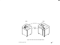
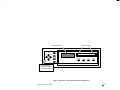
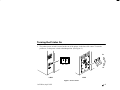
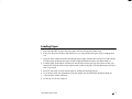
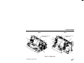
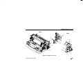
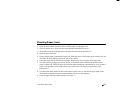
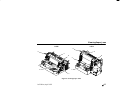
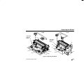
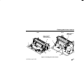
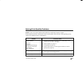
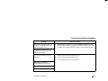
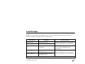
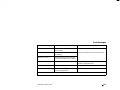
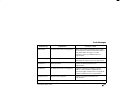
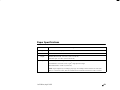
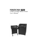
LG06 / LG12 TEXT AND GRAPHICS PRINTER digi tal Operators Guide Order Number: FW–LG0A2–A8 Digital Equipment Corporation 1993 All Rights Reserved The information in this document is subject to change without notice and should not be construed as a commitment by Digital Equipment Corporation. Digital Equipment Corporation assumes no responsibility for any errors that may appear in this document. Printed in U.S.A. The following are trademarks of Digital Equipment Corporation: DATATRIEVE DEC DECmate DECset DECsystem DECUS DECwriter DECxpress digi tal DIBOL IVAX MASSBUS PDP P/OS Professional Rainbow RSTS RSX Scholar ULTRIX UNIBUS VAX VMS VT Work Processor Contents Opening the Printer . . . . . . . . . . . . . . . . . . . . . . . . . . . . . . . . . . . . . . . . . . . . . . . . . . . . . . . . . . . . . . . . . . . 1 Operator Control Panel Switches and Indicators . . . . . . . . . . . . . . . . . . . . . . . . . . . . . . . . . . . . . . . . . . . . . 3 Turning the Printer On . . . . . . . . . . . . . . . . . . . . . . . . . . . . . . . . . . . . . . . . . . . . . . . . . . . . . . . . . . . . . . . . . 6 Loading Paper . . . . . . . . . . . . . . . . . . . . . . . . . . . . . . . . . . . . . . . . . . . . . . . . . . . . . . . . . . . . . . . . . . . . . . . 7 Setting Top–of–Form . . . . . . . . . . . . . . . . . . . . . . . . . . . . . . . . . . . . . . . . . . . . . . . . . . . . . . . . . . . . . . . . . . 9 Clearing Paper Jams . . . . . . . . . . . . . . . . . . . . . . . . . . . . . . . . . . . . . . . . . . . . . . . . . . . . . . . . . . . . . . . . . 11 Replacing the Ribbon . . . . . . . . . . . . . . . . . . . . . . . . . . . . . . . . . . . . . . . . . . . . . . . . . . . . . . . . . . . . . . . . 13 Cleaning the Printer Interior . . . . . . . . . . . . . . . . . . . . . . . . . . . . . . . . . . . . . . . . . . . . . . . . . . . . . . . . . . . 15 Selecting a Font . . . . . . . . . . . . . . . . . . . . . . . . . . . . . . . . . . . . . . . . . . . . . . . . . . . . . . . . . . . . . . . . . . . . 17 Saving Printer Configuration . . . . . . . . . . . . . . . . . . . . . . . . . . . . . . . . . . . . . . . . . . . . . . . . . . . . . . . . . . . 19 Solving Print Quality Problems . . . . . . . . . . . . . . . . . . . . . . . . . . . . . . . . . . . . . . . . . . . . . . . . . . . . . . . . 21 Fault Messages . . . . . . . . . . . . . . . . . . . . . . . . . . . . . . . . . . . . . . . . . . . . . . . . . . . . . . . . . . . . . . . . . . . . . 23 Paper Specifications . . . . . . . . . . . . . . . . . . . . . . . . . . . . . . . . . . . . . . . . . . . . . . . . . . . . . . . . . . . . . . . . . 26 Ribbon Specifications . . . . . . . . . . . . . . . . . . . . . . . . . . . . . . . . . . . . . . . . . . . . . . . . . . . . . . . . . . . . . . . . 27 1st Edition, April 1993 i Opening the Printer To gain access to the printer mechanism, lift the printer cover. (See Figure 1.) The paper supply and stacking areas are located in the floor of the cabinet. The front and rear cabinet doors latch magnetically. The operator control panel is located at the front of the printer. Four switches are accessible with the printer cover up or down. Eight more switches are accessed by raising the printer cover. (See Figure 1 and Figure 2.) 1st Edition, April 1993 1 LG06 LG12 Printer Cover Operator Control Panel Figure 1. The LG06 / LG12 Text and Graphics Printer 1st Edition, April 1993 2 Operator Control Panel Switches and Indicators The operator control panel switches and indicators are illustrated in Figure 2. The functions of the switches and indicators are listed below. Function Control Panel Switch / Indicator Status Lamps NOTE: Only the ON LINE switch operates when the printer is on–line. All other switches operate only in the off–line state. Illuminate when printer is on–line. Flash alternately to indicate a fault condition. Off when printer is off–line. Message Display Displays on–line/off–line state, configuration menus, and fault conditions. ON LINE Toggles the printer between on–line and off–line. FF Press to advance paper to top of form on the next page. LF Press to advance paper to top of next print line. Press with NEXT switch to advance paper in 1/60 inch increments. 1st Edition, April 1993 3 Operator Control Panel Switches and Indicators Control Panel Switch / Indicator Function VIEW Press to advance paper for viewing through cover window; press to return paper to print position. UP Locks and unlocks ENTER switch when pressed simultaneously with DOWN switch. Also causes display of configuration menus, submenus, and diagnostic tests. DOWN See above. PREV Displays previous parameter in a configuration or diagnostic test menu. NEXT Displays next parameter in a configuration or diagnostic test menu. CLEAR Press to clear printer after a fault is corrected. Returns printer to off–line state from within a configuration menu. Resets printer to last saved configuration when pressed simultaneously with R/S switch. R/S Press to run and stop configuration and self tests. Resets printer to last saved configuration when pressed simultaneously with CLEAR switch. SET TOF ENTER Press to cause paper to move in reverse to the first print line. Press to select a displayed parameter. Must be unlocked before using. (Press UP and DOWN switches simultaneously to lock or unlock the ENTER switch.) 1st Edition, April 1993 4 MESSAGE DISPLAY STATUS LAMPS CLEAR UP R/S PREV NEXT SET TOF ON LINE FF LF VIEW ENTER DOWN RAISE PRINTER COVER TO ACCESS THESE SWITCHES Figure 2. Operator Control Panel Switches and Indicators 1st Edition, April 1993 5 Turning the Printer On 1. The printer power switch is located at the rear of the printer, in the lower left corner. To turn the printer on, set the power switch to the On position. (See Figure 3.) On On Off Off LG06 LG12 Figure 3. Power Switch 1st Edition, April 1993 6 Loading Paper 1. Press the ON LINE switch to place the printer off–line and open the printer cover. 2. Fully raise the forms thickness adjustment lever (A). Open both tractor gates (B) by swinging them out. 3. Open the floor cabinet front door and align the paper supply with the label on the floor of the cabinet. Feed the paper up through the paper slot until it appears behind and above the ribbon mask (C). 4. Load the paper on the tractor sprockets (D) and close the tractor gates (B). Press down on the right tractor lock. Slide the tractor to the right to remove slack in the paper. Lift the right tractor lock up to lock it in position. 5. Press FF four times to ensure that the paper is feeding and stacking properly. 6. If you need to make fine adjustments to the left margin, turn the horizontal adjustment knob (E). 7. Close the floor cabinet front door. 8. Set the top–of–form (see page 9). 1st Edition, April 1993 7 Loading Paper LG06 B LG12 C (Behind shuttle cover. Not shown.) E B C (Behind shuttle cover. Not shown.) B E B D D A A Figure 4. Loading Paper 1st Edition, April 1993 8 Setting Top–of–Form 1. Press the ON LINE switch to place the printer off–line and open the printer cover. 2. Make sure several sheets of paper extend past the tractors. If necessary, press the FF switch twice to feed a couple of sheets beyond the tractors and into the paper guide assembly. 3. Fully raise the forms thickness adjustment lever (A). You will hear a beep, indicating that a fault condition exists. 4. Rotate the vertical position knob (B) to set the center of the first printable line at the top–of–form indicator (C) on the left tractor gate. 5. Set the forms thickness adjustment lever (A) to match the paper thickness you are using. (The A–B–C scale corresponds approximately to 1–, 3–, and 6–part paper thickness. Adjust until you have the desired print quality.) The fault condition clears automatically. 6. Press and release the SET TOF switch. The paper reverse feeds to the print position. 7. Close the printer cover. 8. Press the ON LINE switch to place the printer on–line. 1st Edition, April 1993 9 Setting Top–of–Form LG06 LG12 C C A B B A Figure 5. Setting Top–of–Form 1st Edition, April 1993 10 Clearing Paper Jams 1. 2. 3. 4. 5. 6. 7. 8. 9. Open the floor cabinet front door and tear off the paper near the paper slot. Open the printer cover. Fully raise the forms thickness adjustment lever (A). Open both tractor gates (B) and remove the paper from the tractor sprockets (C). Open the paper fence (D). Gently pull the paper up through the paper slot. Slide the paper over the paper guide assembly (E) and down into the paper stacking area in the rear of the cabinet. Check the paper path for bunched or torn paper. Remove any pieces of paper in the paper path. Check the narrow passageway between the face of the platen and the ribbon mask for bits of torn paper or ribbon lint. Check the holes in the ribbon mask surrounding each hammer tip. Gently remove paper or lint particles with a wooden stick or pair of tweezers. (Do not pry or apply force to the hammer tips.) Check that the ribbon mask has not been deformed in such a way as to block the paper path. (If the ribbon mask is damaged or bent, contact an authorized service representative.) Close the paper fence (D) and load paper. (See page 7.) 1st Edition, April 1993 11 Clearing Paper Jams LG06 LG12 D E D E B B A C C A Figure 6. Clearing Paper Jams 1st Edition, April 1993 12 Replacing the Ribbon 1. Press the ON LINE switch to place the printer off–line and open the printer cover. 2. Fully raise the forms thickness adjustment lever (A). 3. Remove the ribbon spools (B) by squeezing the hub latches (C) and lifting up on the spools. Raise the ribbon out of the ribbon path. Discard the old ribbon and spools. 4. Check the ribbon mask and hammer bank cover for bits of torn paper or ribbon lint. Check the holes in the ribbon mask surrounding each hammer tip. Gently remove paper or lint particles with a wooden stick or pair of tweezers. (Do not pry or apply force to the hammer tips.) 5. Place new ribbon spools (B) on the hubs (D), with the ribbon to the outside. 6. Align the spool keyways over the hub latches (C) and press the spools (B) down until the latches snap into place. 7. Thread the ribbon around the ribbon guides (E) and between the hammer bank cover and ribbon mask, as shown on the diagram (F). Turn the ribbon spools to ensure that the ribbon tracks correctly in the ribbon path. 8. Set the forms thickness adjustment lever (A) to match the paper thickness you are using. (The A–B–C scale corresponds approximately to 1–, 3–, and 6–part paper thickness. Adjust until you have the desired print quality.) 9. Close the printer cover and press the ON LINE switch to place the printer on–line. 1st Edition, April 1993 13 Replacing the Ribbon LG06 LG12 B (Left ribbon guide not shown.) E B (Left ribbon guide not shown.) E E A F F A D C D E C Figure 7. Replacing the Ribbon 1st Edition, April 1993 14 Cleaning the Printer Interior 1. 2. 3. 4. 5. 6. 7. 8. Turn off the printer power and unplug the printer. (See page 6.) Open the printer cover. Fully raise the forms thickness adjustment lever (A). Remove all paper (page 7) and the ribbon and spools (page 13). Using a soft–bristled brush and vacuum cleaner, brush and vacuum paper and dust particles from the paper path, ribbon guides (B), ribbon path, and base pan (C). Check the ribbon mask and hammer bank cover for bits of torn paper or ribbon lint. Check the holes in the ribbon mask surrounding each hammer tip. Gently remove paper or lint particles with a wooden stick or pair of tweezers. (Do not pry or apply force to the hammer tips.) Using a soft cloth lightly moistened with denatured alcohol, remove dust and ink from the platen (D). (The platen is the thick silver bar behind the hammer bank cover; it rotates when the forms thickness adjustment lever is rotated.) Brush and vacuum up dust or residue that has accumulated inside the lower cabinet. Wipe the lower cabinet interior with a clean, lint–free cloth dampened (not wet) with water and mild detergent, or spray the surfaces lightly with window cleaning solution. Dry the lower cabinet interior by wiping it with a clean, lint–free cloth. 1st Edition, April 1993 15 Cleaning the Printer Interior LG06 LG12 (Platen is behind hammer bank cover. Not shown.) (Platen is behind ribbon deck. Not shown.) D D A C A B B C Figure 8. Cleaning the Printer Interior 1st Edition, April 1993 16 Selecting a Font NOTE: During normal operation, the message display indicates that the printer is on–line and specifies which printer emulation is currently selected. The procedure below selects an LG06 emulation font. The procedure is the same for the Proprinter XL and Epson FX emulations, but the font options differ. (Refer to Chapter 4, LG06/LG12 User’s Manual.) 1. Press the ON LINE switch to place the printer off–line. 2. Open the printer cover. 3. Press UP and DOWN simultaneously to unlock the ENTER switch. “Unlocked” displays momentarily. 4. Press DOWN. “Emulation/LG06” displays. 5. Press DOWN. “LG06/Font” displays. 6. Press DOWN. “Font/Style” displays. 1st Edition, April 1993 17 Selecting a Font 7. Press DOWN. “Style/[font]” displays. Press NEXT or PREV to cycle through the font options. (DP 10 6 is default. The first number is characters per inch; the second number is lines per inch. The font options are abbreviated on the display: DP = Data Processing; CORESPON = Correspondence; COMPRESS = Compressed; HS = High Speed; OCR A = Optical Character Recognition, Set A; OCR B = Optical Character Recognition, Set B.) 8. When the desired font shows on the display, press ENTER. An asterisk (*) appears on the display, indicating that this font will print. 9. Press CLEAR to return the printer to off–line status. The display reads “Off–Line/Emulation.” 10. Press UP and DOWN simultaneously to lock the ENTER switch. “Locked” displays momentarily. 11. Close the printer cover. 12. Press the ON LINE switch to place the printer on–line. 13. To make the font selection occur automatically when the printer is turned on, save the printer configuration. (See page 19.) 1st Edition, April 1993 18 Saving Printer Configuration Changes to the font or line spacing will be lost when the printer is turned off, unless you save the changes. When you save a set of configuration values, they become the power–up default configuration. To save configuration values: 1. Press the ON LINE switch to take the printer off–line. “Off–Line/Emulation” appears on the message display. 2. Open the printer cover. 3. Press UP and DOWN simultaneously to unlock the ENTER switch. “Unlocked” appears briefly on the message display. 4. Press NEXT (or PREV) until “Off–Line/Save Config” appears on the display. 5. Press ENTER. The printer saves the parameters in nonvolatile memory then displays “Done.” 1st Edition, April 1993 19 Saving Printer Configuration 6. Press CLEAR to return to “Off–Line/Emulation”. 7. Press UP and DOWN simultaneously to lock the ENTER switch. “Locked” appears briefly on the message display. 8. Close the printer cover. 9. Press the ON LINE switch to place the printer on–line. 1st Edition, April 1993 20 Solving Print Quality Problems NOTE: Locate your printer problem in the table below and do the Corrective Action. If more than one corrective action task is listed, test the printer after each task. If the problem persists, contact your authorized service representative. Problem Corrective Action Poor print quality: 1. Reset the forms thickness adjustment lever. (Print quality can be affected if it is too loose or too tight.) dark print light print light print on half the page missing dots or characters smeared print wavy vertical lines 2. Rethread ribbon (see page 13). 3. Clean printer (see page 15). 4. Replace ribbon (page 13) with an approved ribbon (see Ribbon Specifications, page 27). Torn or damaged forms 1. Reset forms thickness adjustment lever for thicker paper. 2. Check paper slot for foreign material. 1. Reset forms thickness adjustment lever for thicker paper. Loss of forms position 1st Edition, April 1993 21 Solving Print Quality Problems Problem Asterisk does not appear after you change a configuration parameter with the ENTER switch. Corrective Action 1. With the printer off–line, press UP and DOWN simultaneously until display reads “Unlocked.” Display the configuration option you want to change. Press ENTER when the option is on the message display. 1. Reset the forms thickness adjustment lever. 2. Clear the paper path of any obstructions. 3. Contact authorized service representative. Configuration printout does not represent configuration parameters selected and changed. Lost dots (incompletely formed characters) Horizontally or vertically misaligned character positions Erratic character height Vertically deformed print 1st Edition, April 1993 22 Fault Messages NOTE: After correcting a fault condition, press CLEAR to continue printing. If the fault message reappears, contact your authorized service representative. Fault Message Explanation 48 Volt Failed * Internal power failure. Dynamic RAM Fault * RAM failure Ham. Bank Hot One or more hammer coils are overheating. Ham. Coil Open * Electrical malfunction of one or more hammer coils. Ham. Coil Short * Electrical malfunction of one or more hammer coils. Corrective Action Contact an authorized service representative. representative Stop printing. Allow printer to cool. If fault recurs, contact an authorized service representative. Contact an authorized service representative. representative * Cycle power; if message reappears, contact your authorized field service representative. 1st Edition, April 1993 23 Fault Messages Fault Message Explanation Corrective Action Ham. Drv. Short * Electrical malfunction of hammer driver system. Mech Driver Hot * Mechanism driver board is overheating. Mech Driver Link * Electronic fault between controller board and mechanism driver board. Paper Jam No paper motion. Clear paper jam. See page 11. Reset forms thickness adjustment lever. Paper Out Printer out of paper. Load paper. See page 7. Platen Open Forms thickness adjustment lever raised to open position. Close forms thickness adjustment lever. Contact an authorized service representative. * Cycle power; if message reappears, contact your authorized field service representative. 1st Edition, April 1993 24 Fault Messages Fault Message Explanation Corrective Action Ribbon Stall No ribbon movement or wrong speed. Reset forms thickness adjustment lever. Check for obstruction to ribbon or ribbon hub. Remove and install ribbon. See page 13. If fault continues, contact your authorized service representative. Shttl Cover Open Shuttle cover open. Reinstall shuttle cover. Make sure the cover lies flat and the two captive screws are fully seated. Shuttle Fan * Shuttle fan failure. Contact an authorized field service representative. Shuttle Jam No shuttle movement or wrong speed. Check for obstruction to shuttle, a twisted ribbon, or forms thickness adjustment lever closed too tightly. If fault source is not apparent, contact an authorized service representative. Software Error * Internal software problem. Contact your authorized field service representative. * Cycle power; if message reappears, contact your authorized field service representative. 1st Edition, April 1993 25 Paper Specifications Item Specification Type Standard fan–folded, edge–perforated Width 3 to 16 in. (7.62 to 40.64 cm) Length Standard (doors closed): 4 to 14 in. (10.16 to 35.56 cm) With doors open: 4 to 24 in. (10.16 to 60.96 cm) Weight 15 to 100 lb. (56.4 to 162.8 g/m2). 1 to 6 parts, carbon or carbonless Recommended: 18 to 20 lb. (68 to 75 g/m2) single part form weight Maximum thickness: 0.025 in. (0.0635 cm) NOTE: Paper weights vary according to paper type. For example, bond is based on one ream (500 sheets) 17 x 22 inches in size, whereas a manila card stock is based on sheet sizes of 24 x 36 inches. 1st Edition, April 1993 26 Ribbon Specifications USE OF RIBBONS THAT DO NOT MEET DIGITAL SPECIFICATIONS MAY VOID WARRANTY. Part Number LGXX–BC (LG06) LG12R–BC (LG12) Description OCR Application, carton of 1 ribbon (LG06 ribbon) Length: Width: Thickness: 60 yards (54.84 m) 1 inch (2.54 cm) .0039 inches (.009906 cm) OCR Application, carton of 1 ribbon (LG12 ribbon) Length: Width: Thickness: 100 yards (91.4 m) 1 inch (2.54 cm) .0039 inches (.009906 cm) To order replacement ribbons, call 1–800–DIGITAL To order electronic parts, call 1–800–234–1998 1st Edition, April 1993 27