1
Agilent 34980A
Multifunction
Switch/Measure Unit
Service Guide
Agilent Technologies
Notices
© Agilent Technologies, Inc. 2006, 2011,
2012, 2013
Warranty
Microsoft and Windows are U.S. registered trademarks of Microsoft Corporation.
The material contained in this document is provided “as is,” and is
subject to being changed, without
notice, in future editions. Further,
to the maximum extent permitted
by applicable law, Agilent disclaims
all warranties, either express or
implied, with regard to this manual
and any information contained
herein, including but not limited to
the implied warranties of merchantability and fitness for a particular purpose. Agilent shall not
be liable for errors or for incidental
or consequential damages in connection with the furnishing, use, or
performance of this document or of
any information contained herein.
Should Agilent and the user have a
separate written agreement with
warranty terms covering the material in this document that conflict
with these terms, the warranty
terms in the separate agreement
shall control.
Software Revision
Technology Licenses
This guide is valid for the firmware that
was installed in the instrument at the time
of manufacture. However, upgrading the
firmware may add or change product
features. For the latest firmware and
documentation, go to the product page at:
The hardware and/or software described
in this document are furnished under a
license and may be used or copied only in
accordance with the terms of such license.
www.agilent.com/find/34980A
U.S. Government Restricted Rights.
Software and technical data rights granted
to the federal government include only
those rights customarily provided to end
user customers. Agilent provides this
customary commercial license in Software and technical data pursuant to FAR
12.211 (Technical Data) and 12.212
(Computer Software) and, for the Department of Defense, DFARS 252.227-7015
(Technical Data - Commercial Items) and
DFARS 227.7202-3 (Rights in Commercial Computer Software or Computer
Software
Documentation).
No part of this manual may be reproduced
in any form or by any means (including
electronic storage and retrieval or translation into a foreign language) without prior
agreement and written consent from
Agilent Technologies, Inc. as governed
by United States and international copyright laws.
Manual Part Number
34980-90010
Edition
Sixth Edition, September 2013
Printed in Malaysia
Agilent Technologies, Inc.
3501 Stevens Creek Blvd
Santa Clara, CA 95052 USA
Safety Notices
CAUTION
A CAUTION notice denotes a
hazard. It calls attention to an
operating procedure, practice, or
the like that, if not correctly performed or adhered to, could result
in damage to the product or loss of
important data. Do not proceed
beyond a CAUTION notice until
the indicated conditions are fully
understood and met.
WA RNING
A WARNING notice denotes a
hazard. It calls attention to an
operating procedure, practice,
or the like that, if not correctly
performed or adhered to, could
result in personal injury or
death. Do not proceed beyond a
WARNING notice until the indicated conditions are fully
understood and met.
Restricted Rights Legend
i
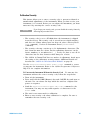
Additional Safety Notices
The following general safety precautions
must be observed during all phases of
operation of this instrument. Failure to
comply with these precautions or with
specific warnings or instructions elsewhere in this manual violates safety standards of design, manufacture, and
intended use of the instrument. Agilent
Technologies assumes no liability of the
customer’s failure to comply with the
requirements.
Do Not Modify the
Instrument
General
Instruments that appear damaged or
defective should be made inoperative and
secured against unintended operation
until they can be repaired by qualified service personnel.
Do not use this products in any manner
not specified by the manufacturer. The
protective features of this product may be
impaired if it is used in a manner not
specified in the operation instructions.
Do not install substitute parts or perform
any unauthorized modification to the
product. Return the product to an Agilent
Sales and Service Office for service and
repair to ensure that safety features are
maintained.
In Case of Damage
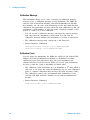
Safety Symbols
Before Applying Power
Verify that all safety precautions are
taken. Make all connections to the unit
before applying power.
Ground the Instrument
This product is provided with protective
earth terminals. To minimize shock hazard, the instrument must be connected to
the ac power mains through a grounded
power cable, with the ground wire firmly
connected to an electrical ground (safety
ground) at the power outlet. Any interruption of the protective (grounding) conductor or disconnection of the protective
earth terminal will cause a potential shock
hazard that could result in personal injury.
Do Not Operate in an Explosive
Atmosphere
Do not operate the instrument in the presence of flammable gases or fumes.
Do Not Remove the Instrument
Cover
Only qualified, service-trained personal
who are aware of the hazards involved
should remove instrument covers. Always
disconnect the power cable and any external circuits before removing the instrument cover.
ii
Waste Electrical and Electronic
Equipment (WEEE) Directive
2002/96/EC
Alternating current
Frame or chassis
terminal
Standby supply. Unit is
not completely
disconnected from ac
mains when switch is off
Caution, risk of
electric shock
Caution, refer to
accompanying
This product complies with the WEEE
Directive (2002/96/EC) marking requirement. The affixed product label (see
above) indicates that you must not discard this electrical/electronic product
in domestic household waste.
Product Category: With reference to the
equipment types in the WEEE directive
Annex 1, this product is classified as a
“Monitoring and Control instrumentation” product.
To return unwanted products, contact
your local Agilent office, or go to
www.agilent.com/environment/product
for more information.
Technical Support
If you have questions about your shipment, or if you need information about
warranty, service, or technical support,
contact
Agilent Technologies:
In the United States: (800) 829-4444
In Europe: 31 20 547 2111
In Japan: 0120-421-345
Or go to www.agilent.com/find/assist
for information on contacting Agilent in
your country of specific location. You can
also contact your Agilent Technologies
Representative.
iii
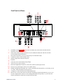
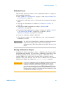
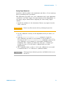
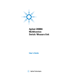
Front Panel at a Glance
1
2
3
4
5
6
7
8
9
10
11
12
13
WARNIN
On/Standby switch WARNINGs..
This switch is standby only. To disconnect the mains from the
instrument, remove the power cord.
Utility menu contains settings for Remote I/O (LAN, GPIB, and USB), Date and Time, and other
system-related instrument parameters
Store/recall menu allows you to save and recall up to six instrument setups
Control keys directly control module actions
Number keypad enters numerical characters
Exponent
Cancel key exits a menu without saving changes
Arrow keys move cursor positions
Knob enters alphanumeric characters, selects slots, channels, and navigates menus
Enter key steps you through a menu or saves number entries
Running a program puts the display into “remote” and disables the front panel keys. Local takes you out
of “remote” mode and enables the front panel keys.
Configure keys select functions and set function parameters
Measure keys execute and monitor measurements. Depending on which measurement key you use, you
can have complete/direct control over the switching and measurement operation, or you can have the
34980A automatically control these to capture the desired data.
34980A Service Guide
iv
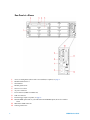
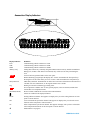
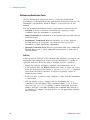
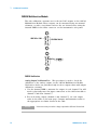
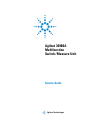
Rear Panel at a Glance
1
2
3
4
5
6
7
8
9
10
11
12
v
Access to Analog Buses (shown with cover installed). For pinout, see page vi.
Module installed in slot 1
Slot identifier
Module ground screw
Slot cover over slot 2
AC power connector
LAN connector (10Base T/100Base Tx)
USB 2.0 connector
External trigger input. For pinout, see page vi.
Internal DMM option mark. If you ordered the internal DMM option, the circle is marked
black.
IEEE 488.2 GPIB Connector
Chassis ground screw
34980A Service Guide
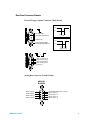
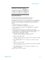
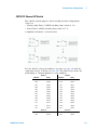
Rear Panel Connector Pinouts
External Trigger/Alarms Connector (Male D-Sub)
Input
5V
0V
6
9
1
5
Ext Trig Input /
Chan Adv Input (Pin 6)
> 1 μs
Output
Gnd (Pin 9)
3.3 V
Chan Closed Output /
VM Comp Output (Pin 5)
0V
Approx. 2 μs
or
Alarm 1 Output (Pin 1)
Alarm 2 Output (Pin 2)
Alarm 3 Output (Pin 3)
Alarm 4 Output (Pin 4)
Gnd (Pin 9)
Analog Bus Connector (Female D-Sub)
ANALOG
BUSSES
ABus1 HI (Pin 9)
ABus2 HI (Pin 8)
ABus3 HI (Pin 7)
ABus4 HI (Pin 6)
34980A Service Guide
9
5
6
1
Internal DMM Current Input I (Pin 5)
ABus1 LO (Pin 4)
ABus2 LO (Pin 3)
ABus3 LO (Pin 2)
ABus4 LO (Pin 1)
vi
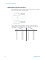
Annunciator Display Indicators
Display Indicator
LAN
USB
GPIB
ABUS [1234]
ERRO
Rmt
Safety Interlock
Trig
HO
ALARM (H1234L)
Definition
Communicating with the 34980A over LAN.
Communicating with the 34980A over USB.
Communicating with the 34980A over GPIB.
Analog Bus Connectivity. Normally, designated ABus connected on any module in mainframe.
During scan, if ABus 1 and ABus 2 are indicated, they will be used at some point during the
scan.
An error has been generated and is in the error queue.
Remote. Running a program puts the display into “remote” and disables the front panel keys.
Pressing the LOCAL button takes you out of “remote” mode and enables the front panel keys.
ABus Safety Interlock. Terminal block or cables have been removed from the D-sub connector of
a module. For more information, see the Agilent 34980A User’s Guide.
Waiting for external or manual trigger during scans.
Over-temperature condition. One or more general purpose (34937A/34938A) modules have
reached their over-temperature limits.
HI or LO alarm condition has occurred on the indicated alarms.
Alarms are enabled on the displayed channel.
Mx+B
4W
OC
*
vii
Scaling enabled on channel. This appears on display after you select scaling function via front
panel or remote interface.
4-wire measurement specified on channel. This appears on display after you select the 4-wire
function via the front panel or remote interface.
Offset Compensation specified on channel. This appears on display after you have selected the
offset compensation function via the front panel or remote interface.
Measurement is in progress.
34980A Service Guide
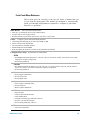
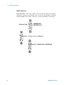
Front Panel Menu Reference
This section gives an overview of the top two levels of menus that you
access from the front panel. The menus are designed to automatically
guide you through all parameters required to configure a particular
function or operation.
Store/Recall
Store and recall instrument states
• Store up to six instrument states in non-volatile memory
• Assign a name to each storage location.
• Recall stored states, power-down state, factory reset state, or preset state
Utility
•
•
•
•
•
Configure system-related instrument parameters
Connecting and configuring to use with LAN, GPIB, or USB
Set the real time clock and calendar
Set radix character, thousand separator
Enable/disable the internal DMM
Query and update the firmware revisions for the mainframe and modules
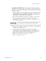
Configure Key Group
Set parameters for measurement
DMM
• Set DMM measurement function (AC volts, DC volts, AC current, DC current, 2-wire ohms, 4-wire ohms,
temperature, frequency, and period)
• Set function parameters
Channel
• Set channel measurement function (AC volts, DC volts, AC current (34921A only), DC current (34921A
only) 2-wire ohms, 4-wire ohms, temperature, frequency, and period)
• Set function parameters
Scan
• Set up trigger-in parameters
• Set up sweep count
• Set up sample count
Sequence
• View sequence command string
• Execute sequence
• Delete sequence definitions
Module
• Open all relays
• Clear all measurement functions
• Clear channel labels
• Configure external trigger and clock (34951A)
• Set trace or level mode (34951A)
• Set waveform parameters (34951A)
View
• View errors and alarms
34980A Service Guide
viii
Advanced
Available at a later firmware release
Alarm
• Select one of four alarms to report alarm conditions on the displayed channel
• Configure a high limit, a low limit, or both for the displayed channel
• Select the slope (rising or falling edge) for the four alarm output lines
ix
34980A Service Guide
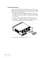
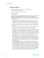
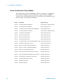
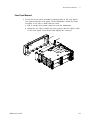
Instrument Rack Mounting
Using the optional Agilent Y1130A Rack Mount Kit, you can mount the
34980A in a standard 19- inch rack cabinet. This kit includes rack mount
brackets and associated hardware required to forward or reverse mount
the instrument in the rack cabinet.
• For forward rack mounting (34980A front panel facing the front of
the cabinet), use the Agilent standard rack mount kit (part number
5063- 9214). For Agilent rack cabinets, use the E3663A Basic Rail Kit
(sold separately).
• For reverse rack mounting (34980A rear panel facing the front of
the cabinet), use the longer brackets (see figure below) with the
hardware for the standard rack mount kit. For Agilent rack cabinets,
use the E3664AC Third Party Rail Kit (sold separately).
Reverse Rack Mount Orientation (longer brackets used)
34980A Service Guide
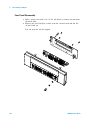
x
425.6 mm (16.76 in)
367.7 mm (14.48 in)
101.9 mm (4.01 in)
or
70.4 mm (2.78 in)
Agilent 34980A Dimensions (shown with Reverse Rack Mount brackets installed)
xi
34980A Service Guide
Contents
Front Panel at a Glance iii
Rear Panel at a Glance
iv
Rear Panel Connector Pinouts
v
Annunciator Display Indicators vi
Front Panel Menu Reference vii
Instrument Rack Mounting
vii
1 Obtaining Service
Operating Checklist 6
Types of Service Available
6
Repackaging for Shipment 7
Cleaning 7
Self Test Procedures
8
Electrostatic Discharge (ESD) Precautions
9
2 Specifications
Multiplexer Module Specifications and Characteristics 12
Matrix Modules Specifications and Characteristics
14
GP Actuator Module Specifications and Characteristics 16
RF and Microwave Module Specifications and Characteristics 17
34945A/34945EXT Module Specifications and Characteristics
19
34950A 64-channel Digital I/O Specifications and Characteristics 20
34951A 4-channel D/A Converter Specifications and Characteristics
22
34952A Multifunction Module Specifications and Characteristics 24
34959A Breadboard Module Specifications and Characteristics
25
Internal DMM Specifications and Characteristics
26
Typical System Speeds
29
Internal DMM Measurement Characteristics
31
System Specifications and Characteristics 35
Product Dimensions 37
To Calculate Total DMM Measurement Error 38
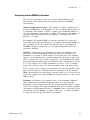
Interpreting Internal DMM Specifications
40
Configuring for Highest Accuracy Measurements
42
34980A Service Guide
1
3 Calibration Procedures
Agilent Technologies Calibration Services 44
Calibration Interval 44
Adjustment is Recommended 44
Time Required for Calibration
45
Automating Calibration Procedures 45
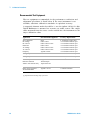
Recommended Test Equipment 46
Calibration Security
47
Calibration Message 48
Calibration Count 48
Calibration Process
49
Aborting a Calibration in Progress 49
Performance Verification Tests
50
Input Connections 52
DMM Test Considerations 53
Internal DMM Verification Tests 53
Optional AC Performance Verification Tests
59
Internal DMM Adjustments 60
Gain Adjustment 61
Plug-in Module Test Considerations
65
34951A 4-Ch Isolated DAC Module 66
34952A Multifunction Module 71
Relay Plug-in Modules 73
Thermocouple Reference Junction 34921A (Optional)
2
75
34980A Service Guide
4 Troubleshooting and Diagnostics
Troubleshooting Hints 78
Power Supply
79
Product Firmware Updates 79
Instrument Errors 80
Error Numbers 82
Isolate a Problem with a Plug-In Module
90
Relay and FET Replacement 91
34921A 40-Channel Armature Multiplexer with Low Thermal Offset
34922A 70-Channel Armature Multiplexer
94
34923A 40/80-Channel Reed Multiplexer 96
34924A 70-Channel Reed Multiplexer 98
34925A 40/80-Channel Optically-Isolated FET Multiplexer
100
34931A Dual 4x8 Armature Matrix 102
34932A Dual 4x16 Armature Matrix 104
34933A Dual/Quad 4x8 Reed Matrix
107
34937A 32-Channel GP Switch 111
34938A 20-Channel High-Current GP Switch 112
92
5 Disassembly and Repair
Electrostatic Discharge (ESD) Precautions
Surface Mount Repair 114
Tools Required 114
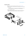
Basic Disassembly
115
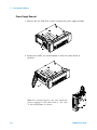
Power Supply Removal 116
Power Supply Disassembly
117
KOM Removal 118
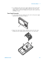
Front Panel Removal 119
Front Panel Disassembly
120
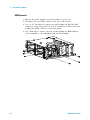
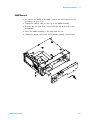
DMM Removal 121
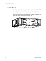
Backplane Removal 122
34980A Service Guide
114
3
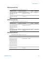
6 Replaceable Parts
To Order Replaceable Parts
124
Backdating and Part Changes 124
Mainframe Replaceable Parts 125
34921A Replaceable Parts
126
34922A Replaceable Parts
126
34923A Replaceable Parts
127
34924A Replaceable Parts
127
34925A Replaceable Parts
127
34931A Replaceable Parts
128
34932A Replaceable Parts
129
34933A Replaceable Parts
130
34937A Replaceable Parts
130
34938A Replaceable Parts
130
34946A and 34947A Replaceable Parts 131
Vendor Addresses
131
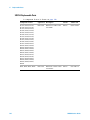
7 Backdating
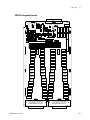
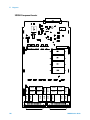
8 Diagrams
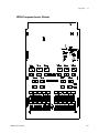
34921A Component Locator 136
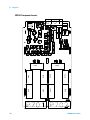
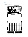
34922A Component Locator 137
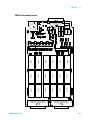
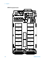
34923A Component Locator 138
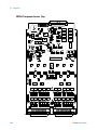
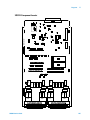
34924A Component Locator 139
34925A Component Locator (Top)
140
34925A Component Locator (Bottom) 141
34931A Component Locator 142
34932A Component Locator 143
34933A Component Locator 144
34937A Component Locator 145
34938A Component Locator 146
4
34980A Service Guide
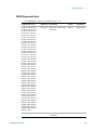
Agilent 34980A Multifunction Switch/Measure Unit
Service Guide
1
Obtaining Service
Operating Checklist 6
Types of Service Available 6
Repackaging for Shipment 7
Cleaning 7
Self Test Procedures 8
Electrostatic Discharge (ESD) Precautions 9
Agilent Technologies
5
1
Obtaining Service
Obtaining Service
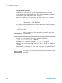
Operating Checklist
Before returning your instrument to Agilent for service or repair check the
following items:
Is the instrument inoperative?
q Verify that the power cord is connected to the instrument and to ac line
power.
q Verify the front panel power switch is depressed.
Does the instrument fail self–test?
q Remove all test connections to the instrument and run the self–test
again.
Errors may be induced by ac signals present on the instrument input
terminals during self–test. Long test leads can act as an antenna
causing pick–up of ac signals.
Types of Service Available
If your instrument fails during the warranty period, Agilent Technologies
will repair or replace it under the terms of your warranty. After your
warranty expires, Agilent offers repair services at competitive prices.
Extended Service Contracts
Many Agilent products are available with optional service contracts that
extend the covered period after the standard warranty expires. If you have
such a service contract and your instrument fails during the covered
period, Agilent Technologies will repair or replace it in accordance with
the contract.
6
34980A Service Guide
Obtaining Service
1
Obtaining Repair Service (Worldwide)
To obtain service for your instrument (in- warranty, under service contract,
or post- warranty), contact your nearest Agilent Technologies Service
Center. They will arrange to have your unit repaired or replaced, and can
provide warranty or repair- cost information where applicable.
To obtain warranty, service, or technical support information you can
contact Agilent Technologies at one of the following telephone numbers:
In the United States: (800) 829- 4444
In Europe: 31 20 547 2111
In Japan: 0120- 421- 345
Or use our Web link for information on contacting Agilent worldwide:
www.agilent.com/find/assist
Or contact your Agilent Technologies Representative.
Before shipping your instrument, ask the Agilent Technologies Service
Center to provide shipping instructions, including what components to
ship. Agilent recommends that you retain the original shipping carton for
use in such shipments.
Repackaging for Shipment
If the unit is to be shipped to Agilent for service or repair, be sure to:
• Remove all accessories or plug- in modules from the mainframe.
• Attach a tag to the unit identifying the owner and indicating the
required service or repair. Include the model number and full serial
number.
• Place the unit in its original container with appropriate packaging
material for shipping.
• Secure the container with strong tape or metal bands.
• If the original shipping container is not available, place your unit in a
container which will ensure at least 4 inches of compressible packaging
material around all sides for the instrument. Use static–free packaging
materials to avoid additional damage to your unit.
Agilent suggests that you always insure shipments.
Cleaning
Clean the outside of the instrument with a soft, lint–free, slightly
dampened cloth. Do not use detergent. Disassembly is not required or
recommended for cleaning.
34980A Service Guide
7
1
Obtaining Service
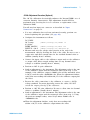
Self Test Procedures
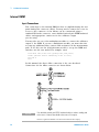
Power–On Self–Test
Each time the instrument is powered on, a subset of self–tests are
performed. These tests check that the minimum set of logic and output
hardware are functioning properly.
Complete Self–Test
To perform a complete self–test send the *TST? command.
This command performs a complete self- test of the instrument and all
installed plug- in modules and returns a pass/fail indication. The self- test
runs a series of tests and, depending upon the modules installed, may take
up to 2 minutes to complete (be sure to set an appropriate interface time
out). If all tests pass, you can have a high confidence that the instrument
and all installed plug- in modules are operational.
If the self–test is successful, SELF–TEST PASSED is displayed on the front
panel.
If the self–test fails, SELF–TEST FAILED is displayed and an error number
is shown. Self–test error numbers and their meaning are shown in the
table on page 85.
NOT E
The self-test will abort if any signals are connected to ABus1 via the
rear-panel Analog Bus connector (pins 4, 5, and 9). Be sure to
disconnect any signals from ABus1 prior to running the self-test.
• On the 34945A Microwave Switch/Attenuator Driver, this command
performs a self- test of the 34945A and all connected 34945EXT remote
modules.
• If you have a 34951A Isolated DAC Module installed, the self- test
will require an additional 15 seconds to complete per DAC module
(a memory test is performed).
If one or more tests fail, return the instrument to Agilent for service.
Self Test Error Numbers
On the remote interface, a self–test failure will generate SCPI error –330
and a supplemental message indicating one of the test numbers shown in
the table on page 85.
Calibration Errors
The table on page 86 shows failures that may occur during a calibration.
8
34980A Service Guide
Obtaining Service
1
Electrostatic Discharge (ESD) Precautions
Almost all electrical components can be damaged by electrostatic discharge
(ESD) during handling. Component damage can occur at electrostatic
discharge voltages as low as 50 volts.
The following guidelines will help prevent ESD damage when servicing the
instrument or any electronic device.
• Disassemble instruments only in a static–free work area.
• Use a conductive work area to reduce static charges.
• Use a conductive wrist strap to reduce static charge accumulation.
• Minimize handling.
• Keep replacement parts in original static–free packaging.
• Remove all plastic, foam, vinyl, paper, and other static–generating
materials from the immediate work area.
• Use only anti–static solder suckers.
34980A Service Guide
9
1
10
Obtaining Service
34980A Service Guide
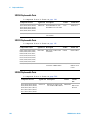
Agilent 34980A Multifunction Switch/Measure Unit
Service Guide
2
Specifications
Multiplexer Module Specifications and Characteristics 12
Matrix Modules Specifications and Characteristics 14
GP Actuator Module Specifications and Characteristics 16
RF and Microwave Module Specifications and Characteristics 17
34945A/34945EXT Module Specifications and Characteristics 19
34950A 64-channel Digital I/O Specifications and Characteristics 20
34951A 4-channel D/A Converter Specifications and Characteristics 22
34952A Multifunction Module Specifications and Characteristics 24
34959A Breadboard Module Specifications and Characteristics 25
Internal DMM Specifications and Characteristics 26
Typical System Speeds 29
Internal DMM Measurement Characteristics 31
System Specifications and Characteristics 34
Product Dimensions 36
To Calculate Total DMM Measurement Error 37
Interpreting Internal DMM Specifications 39
Configuring for Highest Accuracy Measurements 41
Agilent Technologies
11
2
Specifications
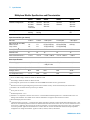
Multiplexer Module Specifications and Characteristics
34921A
34922A
34923A
34924A
34925A
Channels/configurations
40 2-wire
20 4-wire
4-current
1.5 A Fused
70 2-wire
35 4-wire
80 1-wire
40 2-wire
20 4-wire
70 2-wire
35 4-wire
80 1-wire
40 2-wire
20 4-wire
Switch type
Armature
latching
Armature
latching
Reed
Reed
Optically isolated
FET
Input characteristics (per channel)
Max volts
± 300 V [1]
± 300 V [1] ± 150 V peak [2]
± 150 V peak [2]
± 80 V peak [2]
Max current (DC, AC RMS)
Switch current
Carry current
1 A
2A
1 A
2A
0.5 A[4]/0.05 A[9]
1.5 A[4]/0.05 A[9]
0.5 A[5]/0.05 A[9]
1.5 A[5]/0.05 A[9]
0.02 A[6]
Power (W, VA) [5]
60 W
60 W
10 W
10 W
1.6 W
Volt-Hertz limit
108
108
108
108
107
Initial closed channel res [3][10]
< 1.5
< 1.5
< 1.5 5/200 9 < 1.5 5/200 9
< 700
< 3 V
< 3 V
< 50 V
< 100 V 1-wire
< 50 V
< 3 V
>10 G
>10 G
>10 G
>10 G
>10 G
N/A
N/A
N/A
N/A
20 nA [7]
< 1 °C
N/A
N/A
N/A
N/A
General specifications
Offset voltage [3]
DC Isolation (ch-ch, ch-earth)
Leakage current
[3]
T/C cold junction accuracy [3, 8]
[1]
DC or AC RMS voltage, channel-to-channel or channel-to-earth
[2]
Peak voltage, channel-to-channel or channel-to-earth
[3]
Into analog bus. System errors are included in the internal DMM measurement accuracy specifications.
[4]
With in-rush resistors bypassed. Bypassing resistors reduces lifetime of relays. See the rated load relay life characteristics.
[5]
Limited to 6 W of channel resistance power loss per module
[6]
DC or peak AC current
[7] Ambient
[8]
temperature < 30 °C
Includes 0.5 °C temperature reference sensor and 0.5 °C terminal block isothermal gradient error. Measured under worst case
loading of the mainframe. See 34980A User's Guide for information on supported external reference sensors.
[9] With
100 input protection resistors.
[10] Channel resistance is typically < 1.5 but can be as high as 50 when a channel is used in measurement applications with < 1 mA
load current. Increased relay channel resistance for measurements with load currents below 1 mA can occur on cards that have been
out of service or following relay inactivity for periods of greater than 1 week. Switching relays for 2k cycles prior to use typically
corrects this problem. Agilent recommends the use of 4-wire ohms for resistance measurements and the Hi-Z input impedance
configuration for voltage measurements. Applies to 34921A, 34922A, 34923A, and 34924A.
12
34980A Service Guide
Specifications
2
Multiplexer Module Specifications and Characteristics (continued)
34921A
34922A
34923A
34924A
34925A
Bandwidth at terminal block [1] 45 MHz
25 MHz
45 MHz[2]/4 MHz 25 MHz[2]/4
10 MHz 1-wire
MHz[4]
1 MHz
N/A
AC characteristics
Crosstalk
at terminal block (ch-ch) [1]
300 kHz
1 MHz
20 MHz
45 MHz
–75 dB
–75 dB
–50 dB
–40 dB
–75 dB
–75 dB
–50 dB
–75 dB
–75 dB
–50 dB
–40 dB
–75 dB
–70 dB
–45 dB
Capacitance at terminal
block
HI-LO
LO earth
150 pF
150 pF
250 pF
200 pF
130 pF
120 pF
200 pF
170 pF
100 pF
300 pF
(600 pF 1-wire)
Relay life, typical
No load
10 V, 100 mA
Rated load
100 M
10 M
100 k
100 M
10 M
100 k
1000 M
10 M
10 k
1000 M
10 M
10 k
Unlimited
Unlimited
Unlimited
Scanning speeds [3]
100 ch/sec
100 ch/sec
500 ch/sec
500 ch/sec
1000 ch/sec
Open/ close time, typical
4 ms/4 ms
4 ms/4 ms
0.5 ms/0.5 ms
0.5 ms/0.5 ms
0.25 ms/0.25 ms
Analog bus backplane
connection
Yes
Yes
Yes
Yes
Yes
General characteristics
[1]
50 source, 50 load, differential measurements verified with 4-port network analyzer (Sdd21)
[2]
With in-rush resistors bypassed. Bypassing resistors reduces lifetime of relays. See the rated load relay life characteristics.
[3]
Speeds are for 4½ digits, delay 0, display off, autozero off, and within bank.
[4]
With 100 input protection resistors.
34980A Service Guide
13
2
Specifications
Matrix Modules Specifications and Characteristics
34931A
34932A
34933A
34934A
Channels/configurations
dual 4x8
8x8, 4x16
dual 4x16
8x16, 4x32
dual 4x8, 8x8
4x16, quad 4x8,
1-wire
quad 4x32, 4x128,
8x64,16x32
Switch type
Armature
latching
Armature
latching
Reed
non-latching
Reed
non-latching
Max volts
± 300 V [1]
± 300 V [1]
± 150 V peak [2]
± 100 V peak
Max current (DC, AC RMS)
Switch current
Carry current
1 A
2A
1 A
2A
0.5 A[4]/0.05 A[7]
1.5 A[4]/0.05 A[7]
0.5 A
0.5 A
Power (W, VA) [2, 5]
60 W
60 W
10 W[6]
10 W
Volt-Hertz limit
108
108
108
108
Initial closed channel res [3]
< 1.5
< 1.5
< 1.5 [4]/200 [7] < 1 /100
Offset voltage [3]
< 3 V
< 3 V
< 50 V
< 100 V 1-wire
< 20 V
< 50 V 1-wire
DC Isolation (ch-ch, ch-earth)
>10 G
>10 G
>10 G
10 G
Input characteristics (per channel)
General Specifications
[1]
DC or AC RMS voltage, channel-to-channel or channel-to-earth
[2]
Peak voltage, channel-to-channel or channel-to-earth
[3]
Into analog bus. System errors are included in the internal DMM measurement accuracy specifications.
[4]
With in-rush resistors bypassed. Bypassing resistors reduces lifetime of relays. See the rated load relay life characteristics.
[5]
Limited to 6 W channel resistance power loss per module
[6]
Power restrictions allow only 20 channels to be closed at one time.
[7]
With 100 input protection resistors.
[10] Channel resistance is typically < 1.5 but can be as high as 50 when a channel is used in measurement applications with < 1 mA
load current. Increased relay channel resistance for measurements with load currents below 1 mA can occur on cards that have been
out of service or following relay inactivity for periods of greater than 1 week. Switching relays for 2k cycles prior to use typically
corrects this problem. Agilent recommends the use of 4-wire ohms for resistance measurements and the Hi-Z input impedance
configuration for voltage measurements. Applies to 34931A, 34932A.
14
34980A Service Guide
2
Specifications
Matrix Modules Specifications and Characteristics (continued)
34931A
34932A
34933A
34934A
Bandwidth at terminal block [1]
30 MHz
30 MHz
30 MHz[2]/4 MHz [3]
2 MHz 1-wire
35 MHz 2-wire
15 MHz 1-wire
Crosstalk at terminal block (ch-ch) [1]
300 kHz
1 MHz
20 MHz
–65 dB
–55 dB
–30 dB
–65 dB
–55 dB
–30 dB
–65 dB
–55 dB
–40 dB
–65 dB
–55 dB
–33 dB
Capacitance at terminal block
HI-LO
LO - earth
50 pF
80 pF
50 pF
80 pF
80 pF
75 pF
45 pF
250 pF
Relay life, typical
No load
10 V, 100 ma
Rated load
100 M
10 M
100 k
100 M
10 M
100 k
1000 M
10 M
10 k
1000 M operations
Open/close time
4 ms/4 ms
4 ms/4 ms
0.5 ms/0.5 ms
0.35 ms/0.10 ms
Analog bus backplane connection
Bank 2
Bank 2
Bank 2
No
AC characteristics
General characteristics
[1]
50 source, 50 load, differential measurements verified (Sdd21)
[2]
With in-rush resistors bypassed.
[3] With
100 input protection resistors.
34980A Service Guide
15
2
Specifications
GP Actuator Module Specifications and Characteristics
34937A
34938A
Channels/configurations
28 Form C
4 Form A
20 Form A
Switch type
Armature, latching
Armature, latching
Max volts (DC, AC RMS) [1]
Form C — 300 V
Form A — 30 VDC/250 VAC
30 VDC/250 VAC
Max current (DC, AC RMS)
Form C —1 A switch (2 A carry)
Form A — 5 A switch (8 A carry)
5 A switch (8 A carry)
Power (W, VA) [2]
Form C — 60 W
Form A — 150 W
150 W
Volt-Hertz limit
108
108
Offset voltage
3 V
3 V
Initial closed channel res
Form C — 125 m
Form A — 50 m
< 60 m
DC Isolation (ch-ch, ch-earth)
> 10 G
> 10 G
10 MHz
1 MHz
55 dB
35 dB
15 dB
60 dB
40 dB
Form C 12 pF/ Form A 10 pF
Form C 21 pF/ Form A 18 pF
65 pF
105 pF
Relay life no load/rated
Form C — 100 M/100 k
Form A — 50 M/30 k
50 M/30 k
Open/close time
Form C — 4 ms/4 ms
Form A — 10 ms/10 ms
10 ms/10 ms
Initial/reset relay state
Form C — maintain state
Form A — user configurable
User configurable
Analog bus backplane connection
No
No
Input characteristics (per channel)
General specifications
AC characteristics
Bandwidth at terminal block [3]
Channel Isolation at terminal block
100 kHz
1 MHz
10 MHz
Capacitance at terminal block
CH - CH
CH - earth
[3]
General characteristics
[1]
DC or AC RMS voltage, channel-to-channel or channel-to-earth.
[2]
Limited to 6 W of channel resistance power loss per module.
[3]
50 source, 50 load, differential measurements verified (S21).
16
34980A Service Guide
2
Specifications
RF and Microwave Module Specifications and Characteristics
DC to 20 GHz [2]
DC to 3 GHz
34941A
34942A
34946A
34947A
Channels
quad 1x4
quad 1x4
2 SPDT
3 SPDT
Switch type
50 unterminated, 75 unterminated, 50 terminated
latching relays
latching relays
50 unterminated
RF characteristics
[1]
Frequency range [1]
DC to 3 GHz
DC to 1.5 GHz
DC to 4 GHz
or
DC to 20 GHz
DC to 4 GHz
or
DC to 20 GHz
Insertion loss
(< 40°C/80% RH) [1]
100 MHz
1 GHz
3 GHz
0.15 dB
0.60 dB
1.40 dB
0.15 dB
0.60 dB
N/A
DC to 4 GHz < 0.42 dB DC to 4 GHz < 0.42 dB
@ 20 GHz < 0.69 dB
@ 20 GHz < 0.69 dB
VSWR
100 MHz
1 GHz
3 GHz
1.03
1.25
1.55
1.15
1.35
N/A
DC to 4 GHz < 1.15
@ 20 GHz < 1.30
DC to 4 GHz < 1.15
@ 20 GHz < 1.30
Isolation (dB) [1]
100 MHz
1 GHz
3 GHz
Contact Factory
80 dB
58 dB
40 dB
Contact Factory
80 dB
60 dB
N/A
DC to 4 GHz > 85 dB
@ 20 GHz > 67 dB
DC to 4 GHz > 85 dB
@ 20 GHz > 67 dB
Spurious noise
below 1.3 GHz
–140 dBm
–140 dBm
80 dB
80 dB
Risetime
< 80 ps
< 160 ps
N/A
N/A
Signal delay
< 1 ns
< 1 ns
N/A
N/A
Capacitance
< 30 pF
< 30 pf
N/A
N/A
50 source, 50 load (75 for 34942A)
[2]
For more detailed specifications, see the N1810TL for the 34946A and N1810UL for the 34947A. The M9046A and M9047A
requires N1810 Switch Options 124 (24 volt coils), 201 (D submin. 9-pin conn.), and 402 (Position Indicators)
34980A Service Guide
17
2
Specifications
RF and Microwave Module Specifications and Characteristics (continued)
DC to 20 GHz [2]
DC to 3 GHz
34941A
34942A
34946A
34947A
Switching characteristics
Max volts [1]
30 V
30 V
7 V DC
7 V DC
Max current
0.5A
0.5A
N/A
N/A
Max power (W)
10 W [4]
10 W [4]
1W @ 7 VDC,
50W peak [3]
1W @ 7 VDC,
50W peak [3]
Offset voltage
10 V
10 V
N/A
N/A
Initial channel
resistance
1
1
N/A
N/A
Volt-Hertz limit
2 x 10¹⁰
2 x 10¹⁰
General characteristics
Relay life
300,000 at 30V/10mA load; 300,000 at 30V/10mA
100,000 at 10 W load
load;
RF SAmeas
100,000 at 10 W load
RF SAmeas
> 5 M cycles,
1M w/drive
28-32VDC
> 5 M cycles,
1M w/drive
28-32VDC
Open/Close
time
18 ms / 18 ms
18 ms / 18 ms
< 15 ms / 15 ms
< 15 ms / 15 ms
Connector type
SMA
Mini 75 SMB
SMA
SMA
Analog bus
backplane
connection
No
No
No
No
[1]
Channel-to-earth
[2]
For more detailed specifications, see the N1810TL for the 34946A and N1810UL for the 34947A. The M9046A and M9047A
requires N1810 Switch Options 124 (24 volt coils), 201 (D submin. 9-pin conn.), and 402 (Position Indicators)
[3]
10 sec maximum duration
[4]
Max power is 1 W between 30 MHz and 1 GHz for CISPR 11 compliance
18
34980A Service Guide
Specifications
2
34945A/34945EXT Module Specifications and Characteristics
34945EXT switch drive (64 channels, low side drive mode)
Driver off voltage (max)
30V
Driver off leakage current
500 A
Driver on current (max)
600 mA
Driver on voltage (max)
0.5 V @ 600 mA
34945EXT switch drive (64 channels, TTL drive mode)
Hi output voltage
3 V @ Iout = 2 mA
Lo output voltage
0.4 V @ Iin = 20 mA
Lo input Current
20 mA
34945EXT position indicator sense inputs
Channels
64
Lo input voltage (max)
0.8 V
Hi input voltage (min)
2.5 V
Input resistance
> 100 k@ Vin 5 V
> 20 k@ Vin 5 V
Maximum input voltage
30 V
34945EXT switch drive power supply
(34945EXT powered by 34945A)
Voltage
24 V nominal (external power supply required
for switches needing more than 24 V)
Current
100 mA continuous +
200 mA (15 msec pulse, 25% duty cycle)
34945EXT external power connection
Voltage range
4.75 V to 30 V
Current limit
2A
LED indicators (current mode drivers)
Channels
64
Supply voltage
5 V nominal
LED drive current
5 mA nominal
(programmable 1 to 20 mA)
Compliance voltage
0.8 V
34945EXT Dimensions
11.2 x 4.5 x 1.5 inches high with
distribution boards installed
34980A Service Guide
19
2
Specifications
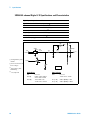
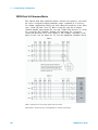
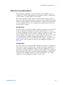
34950A 64-channel Digital I/O Specifications and Characteristics
Digital input/output characteristics
Eight 8-bit channels: 8 bits wide, input or output, non-isolated
Vin
0 V – 5 V [1]
Vout
1.66 V – 5 V [1]
Iout (max)
24 mA [2]
Frequency (max)
10 MHz [3]
Iload (max)
400 mA
trise + tfall Output (typ)
6 ns [4]
10K
+5V
Vcc
+5.1V
OE
DOUT
VREF
Zo = 10
2.5 pF
EN
Rpullup
14.7
26.1
I/O
+5V
[1]
Configurable by 8-bit
channel
+
DIN
-
VTHREF
[2]
Lower current drive at
lower voltages
1M
1 of 64
[3]
From memory with
handshaking
[4]
20
5 V, 50pF load
Active Drive:
Open Collector:
Vin
Vout (L)
Vout (H)
Vout
Vcc (< 2V)
Vcc (> 2V)
0 V – 5 V
0.24 V < Vout < 0.55 V
4 mA < Iout < 24 mA
1.6 V < Vout < 5 V
-4 mA < Iout < -24 mA
0 V – 5 V
-4 mA < Iout < -24 mA
215 < Rpullup < 1 k
215 < Rpullup < 10 k
34980A Service Guide
Specifications
2
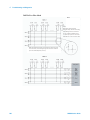
34950A 64-channel Digital I/O Specifications and Characteristics (continued)
Handshake lines
Vin
0 V – 5 V [1]
Vout
1.66 V – 5 V [1,2]
I out (max)
24 mA [2]
Frequency (max)
10 MHz
Counter function characteristics
Maximum frequency
10 MHz (max) 50% duty
Vin
0 V – 5 V [3]
trise / tfall Input (min)
5 s
Totalizer function characteristics
Maximum count
232 – 1 (4,294,967,296)
Maximum input frequency
10 MHz
rising or falling edge programmable
Vin
0 V – 5 V [3]
Gate input
0 V – 5 V [3]
System clock generator characteristics
Frequency
20 MHz – 10 Hz configurable
divide-by-n 24-bits, programmable on/off
Vout
1.66 V – 5 V [2]
Accuracy
100 ppm
[1]
Configurable by bank
[2]
Lower current drive at lower voltages
[3]
Maximum threshold setting of 3V
34980A Service Guide
21
2
Specifications
34951A 4-channel D/A Converter Specifications and Characteristics
General specifications
Maximum update rate
200 kHz point-to-point
Monotonic
to 16-bits
Isolation
> 80 VDC/AC peak (chan-to-chassis or chan-to-chan)
Synchronization
Software commands or external trigger
Internal/external CLK accuracy
100 ppm
AC accuracy
Not specified
DC voltage
Amplitude
± 16 V up to 10 mA
Resolution
16-bits = 500 V
Amplitude accuracy (DC)
± (0.05% + 3.0 mV) 90 days, Tcal ± 5 C or CAL:MOD? ± 5C
Ripple and noise
< 2 mVrms, 20 Hz to 250 kHz into 10 k load
Settling time
40 S (–full scale to +full scale step, single channel, to rated accuracy)
Output impedance
< 1 with the load sensed
DC current
Range
± 20 mA
Resolution
16-bit = 630 nA
Accuracy
± (% value + amps) temperature within ± 5 C of Tcal or *CAL?
90-day: ± (0.09% + 5.0 A)
Ripple and noise
< 2 Arms, 20 Hz to 250 kHz into 250
Compliance voltage
±12 V
Max open circuit voltage
< ± 22 V
22
34980A Service Guide
Specifications
2
34951A 4-channel D/A Converter Specifications and Characteristics (continued)
Phase-locking I/O trigger characteristics
Trigger input
Input level
TTL compatible (3.3 V logic, 5 V tolerant)
Slope
Rising or falling, selectable
Pulse width
> 100 nS
Input impedance
> 10 k, DC coupled
Trigger output
Level
TTL compatible into 1 k(3.3 V logic)
Output impedance
50 typical
Clock input
Input level
TTL compatible (3.3 V logic, 5 V tolerant)
Input impedance
> 10 k, DC
Maximum rate:
10 MHz
Clock output
Level
TTL compatible into 1 k (3.3 V logic)
Output impedance
50 typical
Maximum rate
10 MHz
Accuracy
± 100 ppm
34980A Service Guide
23
2
Specifications
34952A Multifunction Module Specifications and Characteristics
Digital input/output characteristics
Four 8-bits channels, 8 bits wide, input or output, non-isolated
Vin(L)
< 0.8 V (TTL)
Vin(H)
> 2.0 V (TTL)
Vout(L)
< 0.8 V @ Iout = –400 mA
Vout(H)
> 2.4 V @ Iout = 1 mA
Vin(H) (max)
< 42 V with external open drain pull-up
Alarm
Maskable pattern match or state change
Speed
4 ms (max) alarm sampling
Latency
5 ms (typical) to 34980A alarm output
Read/write speed
95/s
Totalize input characteristics
Max count
226 – 1
Totalize input
100 kHz (max) rising or falling edge, programmable
Signal level
1 Vp-p (min) 42 Vpk (max)
Threshold
0 V or TTL
Gate input
TTL-Hi, TTL-Lo, or none
Count reset
Manual or read + reset
Read speed
85 rds/s
Analog output characteristics
24
DAC 1, 2
± 12 V, non-isolated
Resolution
1 mV
IOUT
10 mA max
Settling time
1 ms to 0.01% of output
Accuracy
± (% of output + mV)
1 year: ± (0.25% + 20 mV)
Temperature coefficient
± (0.015% + 1mV)/°C
34980A Service Guide
Specifications
2
34959A Breadboard Module Specifications and Characteristics
General specifications
Maximum module power dissipation 6 W
Power available
12 V regulation no load to full load
5 V regulation no load to full load
Maximum power from 12 V
Maximum power from 5 V
10%
5%
6 W
1W
Relay drives
28, sink up to 100 mA
GPIO ports
34980A Service Guide
Channel 1 and 2
8 configure bits as input or output
Channel 3
3 output bits
Dimensions (L x W x H)
5.4 x 7.5 x 0.9 inches (without PC board)
5.4 x 7.5 x 0.7 inches (with PC board)
25
2
Specifications
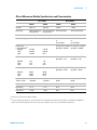
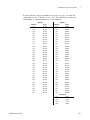
Internal DMM Specifications and Characteristics
DC and Resistance Specifications
DMM accuracy ± (% of reading + % of range). Includes measurement error, switching error[1], and
transducer conversion error.
Test Current or 24 hour [2,3]
Burden Voltage Tcal ± 1 °C
Function
Range [4]
DC voltage
(with 34921A/
22A/25A/31A/32A)[6]
Input impedance = Hi-Z
10 V range and below
100.0000 mV
1.000000 V
10.00000 V
100.0000 V
300.0000 V
Resistance [5]
100.0000 1mA
1.000000 k 1mA
10.00000 k 100 A
100.0000 k 10 A
1.000000 M 5.0A
10.00000 M 500nA
100.0000 M 500nA/10M
90 days
Tcal ± 5 °C
1 year
Tcal ± 1 °C
Temperature
coefficient
Tcal ± 5 °C
0.0030 + 0.0035
0.0020 + 0.0006
0.0015 + 0.0004
0.0030 + 0.0006
0.0030 + 0.0020
0.0040 + 0.0040
0.0030 + 0.0007
0.0020 + 0.0005
0.0045 + 0.0006
0.0045 + 0.0030
0.0050 + 0.0040
0.0040 + 0.0007
0.0035 + 0.0005
0.0055 + 0.0006
0.0055 + 0.0030
0.0005 + 0.0005
0.0005 + 0.0001
0.0005 + 0.0001
0.0005 + 0.0001
0.0005 + 0.0003
0.0030 + 0.0035
0.0020 + 0.0006
0.0020 + 0.0005
0.0020 + 0.0005
0.002 + 0.001
0.015 + 0.001
0.300 + 0.010
0.008 + 0.004
0.008 + 0.001
0.008 + 0.001
0.008 + 0.001
0.008 + 0.001
0.020 + 0.001
0.800 + 0.010
0.010 + 0.004
0.010 + 0.001
0.010 + 0.001
0.010 + 0.001
0.010 + 0.001
0.040 + 0.001
0.800 + 0.010
0.0006 + 0.0005
0.0006 + 0.0001
0.0006 + 0.0001
0.0006 + 0.0001
0.0010 + 0.0002
0.0030 + 0.0004
0.1500 + 0.0002
DC current (34921 only) 10.00000 mA < 0.1 V burden 0.005 + 0.010 0.030 + 0.020 0.050 + 0.020
100.0000 mA < 0.6V
0.010 + 0.004 0.030 + 0.005 0.050 + 0.005
1.000000 A < 2V
0.050 + 0.006 0.080 + 0.010 0.100 + 0.010
0.002 + 0.0020
0.002 + 0.0005
0.005 + 0.0010
One hour warm-up and a fixed configuration with slow AC filter, sine wave input, and 6½ digits.
Temperature within ±5 °C of temperature at calibration (Tcal between 18-28 °C).
[1]
[2]
90 minute warm-up and a fixed configuration and 6½ digits. Temperature within ±1 °C of temperature at calibration (Tcal between
18-28 °C).
[3]
Relative to calibration standards
[4]
20% over range on all ranges except 300VDC and AC ranges and 1 ADC and AC current ranges
[5] Accuracy for 4-wire ohms or 2-wire ohms with scaling to remove offset; add 4 additional error plus the lead wire resistance to the
2-wire ohms function without scaling. The 34921A and 34922A may have increased relay channel resistance, up to an additional
50 which can occur on modules that have been out of service or following relay inactivity for periods of greater than 1 week. Using
4-wire measurements or switching relays for 2k cycles prior to use typically corrects this problem.
[6]
26
Add 50 V error for 34923/24/33.
34980A Service Guide
Specifications
2
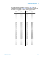
AC Specifications ±(% of reading + % of range)
DMM accuracy ± (% of reading + % of range). Includes measurement error, switching error[1],
and transducer conversion error.
Function
Range [4]
Frequency
24 hour [2,3]
Tcal ± 1 °C
90 days
Tcal ± 5 °C
1 year
Tcal ± 1 °C
Temperature
coefficient
Tcal ± 5 °C
True RMS
AC voltage [5]
100.0000 mV to
100.0000 V
3Hz-5Hz
5Hz-10Hz
10Hz-20kHz
20kHz-50kHz
50kHz-100kHz
100kHz-300kHz [6]
3Hz-5Hz
5Hz-10Hz
10Hz-20kHz
20kHz-50kHz
50kHz-100kHz
100kHz-300kHz [6]
1.00 + 0.03
0.35 + 0.03
0.04 + 0.03
0.10 + 0.05
0.55 + 0.08
4.00 + 0.50
1.00 + 0.05
0.35 + 0.05
0.04 + 0.05
0.10 + 0.10
0.55 + 0.20
4.00 + 1.25
1.00 + 0.04
0.35 + 0.04
0.05 + 0.04
0.11 + 0.05
0.60 + 0.08
4.00 + 0.50
1.00 + 0.08
0.35 + 0.08
0.05 + 0.08
0.11 + 0.12
0.60 + 0.20
4.00 + 1.25
1.00 + 0.04
0.35 + 0.04
0.06 + 0.04
0.12 + 0.05
0.60 + 0.08
4.00 + 0.50
1.00 + 0.08
0.35 + 0.08
0.06 + 0.08
0.12 + 0.12
0.60 + 0.20
4.00 + 1.25
0.100 + 0.004
0.035 + 0.004
0.005 + 0.004
0.011 + 0.005
0.060 + 0.008
0.20 + 0.02
0.100 + 0.008
0.035 + 0.008
0.005 + 0.008
0.011 + 0.012
0.060 + 0.020
0.20 + 0.05
0.10
0.05
0.03
0.006
0.10
0.05
0.03
0.01
0.10
0.05
0.03
0.01
0.005
0.005
0.001
0.001
1.00 + 0.04
0.30 + 0.04
0.10 + 0.04
1.00 + 0.5
0.30 + 0.5
0.10 + 0.5
1.00 + 0.04
0.30 + 0.04
0.10 + 0.04
1.00 + 0.5
0.30 + 0.5
0.10 + 0.5
1.00 + 0.04
0.30 + 0.04
0.10 + 0.04
1.00 + 0.5
0.30 + 0.5
0.10 + 0.5
0.100 + 0.006
0.035 + 0.006
0.015 + 0.006
0.100 + 0.006
0.035 + 0.006
0.015 + 0.006
300.0000 V
Frequency and 100mV to 300V 3Hz-5Hz
period [7]
5Hz-10Hz
10Hz-40Hz
40Hz-300kHz
True RMS AC
current
(34921A only)
3Hz-5Hz
5Hz-10Hz
10Hz-5kHz
[8]
3Hz-5Hz
100.0000 mA
5Hz-10Hz
10Hz-5kHz
10.00000 mA
and [5] 1.0 A
One hour warm-up and a fixed configuration with slow AC filter, sine wave input, and 6½ digits.
Temperature within ±5 °C of temperature at calibration (Tcal between 18-28 °C).
[1]
90 minute warm-up and a fixed configuration and 6½ digits. Temperature within ±1 °C of temperature
at calibration (Tcal between 18-28 °C).
[2]
[3]
Relative to calibration standards
[4]
20% over range on all ranges except 300VDC and AC ranges and 1 ADC and AC current ranges
For sine wave input > 5% of range. For inputs from 1% to 5% of range and < 50 kHz add 0.1% of range
additional error. For AC filter slow.
[5]
[6]
Typically 30% of reading error at 1 MHz, limited to 1 x 10⁸ volt-hertz
[7]
Input > 100 mV. For 10 mV inputs multiply % of reading error x 10. For 1 second aperture (6½ digits).
[8]
Specified only for inputs > 10 mA. For AC filter slow.
34980A Service Guide
27
2
Specifications
Additional Low Frequency Error for ACV, ACI (% of reading)
Frequency
AC Filter Slow AC Filter Medium AC Filter Fast
–
–
0.73
0.22
0.18
0
0.74
0.22
0.06
0.01
0
0
0
0
0
0
0
0
10 Hz – 20 Hz
20 Hz – 40 Hz
40 Hz – 100 Hz
100 Hz – 200 Hz
200 Hz – 1 kHz
>1 kHz
Additional Error for Frequency, Period (% of reading)
Aperture (Digits)
Frequency
1 second
(6 digits)
0.1 seconds
(5 digits)
0.01 seconds
(4 digits)
0
0
0
0
0
0
0
0.12
0.17
0.2
0.06
0.03
0.01
0
0.12
0.17
0.2
0.21
0.21
0.07
0.02
3 Hz – 5 Hz
5Hz – 10 Hz
10 Hz – 40 Hz
40 Hz – 100 Hz
100 Hz – 300 Hz
300 Hz – 1 kHz
>1 kHz
Temperature Specifications
Temperature
Thermocouple
(34921A only, includes
cold junction accuracy on
terminal block)
Type
B
E
J
K
N
R
S
T
1-year accuracy [1] 24 hour Extended range[1] 1-year Temp
accuracy Coefficient
1100 °C to 1820 °C
–150 °C to 1000 °C
–150 °C to 1200 °C
–100 °C to 1200 °C
–100 °C to 1300 °C
300 °C to 1760 °C
400 °C to 1760 °C
–100 °C to 400 °C
1.2 °C
1.0 °C
1.0 °C
1.0 °C
1.0 °C
1.2 °C
1.2 °C
1.0 °C
400 °C to 1100 °C 1.8 °C
–200 °C to –150 °C1.5 °C
–210 °C to –150 °C1.2 °C
–200 °C to –100 °C1.5 °C
–200 °C to –100 °C1.5 °C
–50 °C to 300 °C 1.8 °C
–50 °C to 400 °C 1.8 °C
–200 °C to –100 °C 1.5 °C
0.03 °C
0.03 °C
0.03 °C
0.03 °C
0.03 °C
0.03 °C
0.03 °C
0.03 °C
RTD
Ro from 49 to –200 °C to 600 °C
2.1 k
0.06 °C
0.003 °C
Thermistor
2.2k, 5k, 10k
0.08 °C
0.002 °C
[1]
28
–80 °C to 150 °C
For total measurement accuracy, add temperature probe error.
34980A Service Guide
2
Specifications
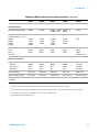
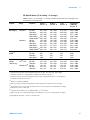
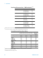
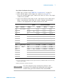
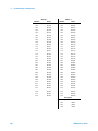
Typical System Speeds
Measurements made on a 3.2 GHz PC running VB6 in Windows XP Professional.
Single Channel Reading
Time (in msec)
Direct Measurements – direct to I/O
(includes switch, measure time, and I/O time)
Direct
Measurment to
Memory (GPIB)
Single Channel [1, 2]
GPIB
USB 2.0
LAN
(w/VXI 11)
Measurement
into memory
Single Channel, DCV
2.83 ms
3.14 ms
4.57 ms
1.9 ms
Single Channel, ACV
5.00 ms
5.35 ms
5.75 ms
4 ms
Single Channel, Ohms
2.91 ms
3.14 ms
4.65 ms
1.9 ms
Single Channel while
changing scale
(e.g. MEAS DCV 10 to
MEAS DCV 1)
9.52 ms
10.64 ms
11.76 ms
8.4 ms
Single Channel while
changing function
(e.g. MEAS ACV to
MEAS DCV)
128 ms
120 ms
120 ms
120 ms
34925A
Open or Close
Read?
Close/Read/Open
Init/*WAI
Close/Init/Open
0.7
2.9
4.8
1.9
3.7
0.9
3.3
5.3
2.1
4.1
1.6
4.7
6.5
3
4.7
34923A
Open or Close
Read?
Close/Read/Open
Init/*WAI
Close/Init/Open
0.9
2.9
5.3
1.9
4.2
1.2
3.3
5.8
2.1
4.7
1.8
4.7
6.5
3
5.2
34921A
Open or Close
Read?
Close/Read/Open
Init/*WAI
Close/Init/Open
4.7
2.9
14
1.9
12.4
5
3. 3
15
2.1
14
5.3
4.7
15
3
14
Command Execution Time [3]
[1]
Readings were made with minimum NPLC, delay 0, display off, autozero off.
[2]
All times include the issue of “READ?” and the retrieval of data.
[3] CLOSE or OPEN bus transfer times allowed to overlap previous command. Command parse times overlap current activity until I/O
latency dominant.
34980A Service Guide
29
2
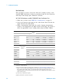
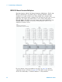
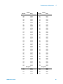
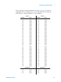
Specifications
Single Channel Measurement Rates — DMM Reading Rates [1, 2]
Function
Resolution
DCV
4-1/2 digits (0.02 plc)
5-1/2 digits (1 plc)
6-1/2 digits (10 plc)
3000
59
6
2-wire Resistance
4-1/2 digits (0.02 plc)
5-1/2 digits (1 plc)
6-1/2 digits (10 plc)
2000
58
6
Thermocouple
(0.02 plc)
0.1°C (1 plc)
2000
59
RTD/Thermistor
1°C (0.02 plc)
0.1°C (1 plc)
0.01°C (10 plc)
1900
58
6
ACV
6-1/2 fast (200 Hz)
6-1/2 Med (20 Hz)
6-1/2 slow (3 Hz)
350
350
300
Frequency, period
4-1/2 digits (10 ms)
5-1/2 digits (100 ms)
6-1/2 digits (1 s gate)
70
9
1
[1]
Reading speeds for 60 Hz; autozero OFF
[2]
For fixed function and range, readings to memory, scaling and alarms off, autozero OFF
Rdgs/s
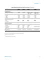
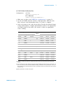
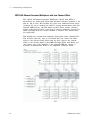
Scanning Measurement Rates to Bus or Memory
Direct Measurements – direct to I/O
(includes switch, measure time, and I/O time)
Scanning Channels [1]
Scanning DCV or Ohms
34925A
34923A/24A
34921A/22A
Scanning ACV [2]
34925A
34923A/24A
34921A/22A
Scanning Temperature
34921A
Scanning Digital in
34950A
Direct
Measurment to
Memory
LAN (w/VXI 11) Into memory
ch/sec
ch/sec
GPIB
ch/sec
USB 2.0
ch/sec
920
588
109
860
572
109
980
605
109
1000
625
109
318
260
88
315
260
88
323
260
88
318
260
88
109
109
109
109
660
592
815
1038
Speeds are for 4½ digits, delay 0, display off, autozero off. Scanning is within bank on the same module.
Add 10 ms for between banks or modules.
[1]
[2]
30
Add additional time for filter setting on ACV.
34980A Service Guide
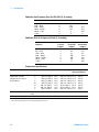
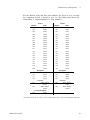
2
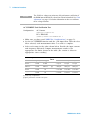
Specifications
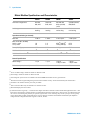
Data Out of Memory to LAN, USB, or GPIB
Data transfer rate with 1000 channel blocks.
GPIB
rdgs/sec
USB 2.0
rdgs/sec
LAN (w/VXI 11)[1]
rdgs/sec
Readings
2560
2400
3542
Readings with Timestamp
1304
1230
1826
Readings with all Format Options
ON
980
926
1361
[1] LAN large block throughput rate is increased by approximately 30% using LAN sockets.
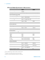
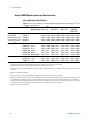
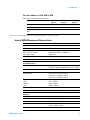
Internal DMM Measurement Characteristics
DC voltage
Measurement method
Continuously integrating multi-slope III A-D converter
A-D linearity
0.0002% of reading + 0.0001% of range on 10 V range
Input resistance
100 mV, 1 V, 10 V ranges
100 V, 300 V ranges
Selectable 10 M or > 10,000 M
10 M ±1%
Input bias current
< 50 pA at 25 °C
Input Protection
300 V all ranges
True RMS AC voltage
Measurement method
AC coupled True RMS - measures the AC component
of the input with up to 300 VDC of bias on any range
Crest factor
Maximum of 5:1 at full scale
Additional crest factor errors
(non-sinewave)
Crest factor 1-2 0.05% of reading
Crest factor 2-3 0.15% of reading
Crest factor 3-4 0.30% of reading
Crest factor 4-5 0.40% of reading
AC Filter Bandwidth
Slow
Medium
Fast
3 Hz – 300 kHz
20 Hz – 300 kHz
200 Hz – 300 kHz
Input impedance
1 M ±2% in parallel with 150 pF
Input protection
300 Vrms all ranges
Resistance
34980A Service Guide
Measurement method
Selectable 4-wire or 2-wire ohms
Current source
Referenced to LO input
Offset compensation
Selectable on 100 , 1 k, and10 k ranges
Maximum lead resistance
10% of range per lead for 100 and 1 k ranges.
1 k on all other ranges
Input protection
300 V on all ranges
31
2
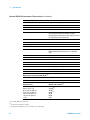
Specifications
Internal DMM Measurement Characteristics (continued)
Frequency and period
Measurement method
Reciprocal counting technique
Voltage ranges
Same as AC voltage function
Gate time
1s, 100 ms, or 10 ms
Measurement time-out
Selectable 3 Hz, 20 Hz, 200 Hz LF limit
Measurement Consideration
All frequency counters are susceptible to error when
measuring low-voltage, low-frequency signals.
Shielding inputs from external noise pickup is critical
for minimizing measurement errors.
DC Current
Shunt resistance
5 for 10 mA, 100 mA; 0.1 for 1 A
Input protection
1A 250 V fuse on 34921A module
True RMS AC current
Measurement method
Direct coupled to the fuse and shunt. AC coupled True
RMS measurement (measures the ac component
only).
Shunt resistance
5 for 10 mA; 0.1 for 100 mA, 1 A
Input protection
1A 250 V fuse on 34921A module
Thermocouple
Conversion
ITS-90 software compensation
Reference junction type
Internal, fixed, or external
Open thermocouple check
Selectable per channel. Open > 5 k
Thermistor
44004, 44007, 44006 series
RTD
= 0.00385 (DIN) and = 0.00392
Measurement noise rejection 60 (50) Hz [1]
DC CMRR
140 dB
AC CMRR
70 dB
Integration time
Normal mode rejection [2]
200 plc/3.33 s (4 s)
100 plc/1.67 s (2 s)
20 plc/333 ms (400 ms)
10 plc/167 ms (200 ms)
2 plc/33.3 ms (40 ms)
1 plc/16.7 ms (20 ms)
< 1 plc
105 dB [3]
100 dB [3]
95 dB [3]
90 dB [3]
85 dB
60 dB
0 dB
[1]
For 1 k unbalance in LO lead
[2]
For power line frequency ±0.08%
[3]
For power line frequency ±1% use 75 dB or ±2.5% use 60 dB
32
34980A Service Guide
2
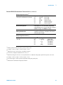
Specifications
Internal DMM Measurement Characteristics (continued)
DC Operating Characteristics [1]
Function
DCV[4], DCI, and Resistance (10 k)
Digits [2]
6½
6½
5½
5½
4½
Auto Zero OFF Operation
Following instrument warm-up at calibration
temperature ±1°C and <10 minutes, add 0.0002%
range additional error +5 µV. (For 300 VDC, instead of
0.0002% of range, use 0.00066% of range)
Settling Considerations
Reading settling times are affected by source
impedance, low dielectric absorption characteristics,
and input signal changes.
Readings
0.6 (0.5)
6 (5)
60 (50)
300
600
Additional RMS Noise Error
0% of range
0% of range
0.001% of range
0.001% of range [3]
0.01% of range [3]
AC Operating Characteristics [5]
Function
ACV, ACI
Digits [6]
6½
6½
5½
6½
6½
Readings/s
7 s/reading
1
8 [7]
10
100 [8]
AC Filter
Slow (3 Hz)
Medium (20 Hz)
Fast (200 Hz)
Fast (200 Hz)
Fast (200 Hz)
[1]
Reading speeds for 60 Hz and (50 Hz) operation; autozero OFF
[2]
6½ digits = 22 bits; 5½ digits = 18 bits; 4½ digits = 15 bits
[3]
Add 20 V for DCV, 4 A for DCI, or 20 m for resistance.
[4)
For 300 VDC, multiply the additional noise error by 3.3.
[5]
Maximum reading rates for 0.01% of AC step additional error. Additional settling delay required when input DC level varies.
[6]
6½ digits = 22 bits; 5½ digits = 18 bits; 4½ digits = 15 bits
[7]
For external trigger or remote operation using default settling delay (Delay Auto)
[8]
Maximum limit with default settling delays defeated
34980A Service Guide
33
2
Specifications
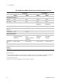
System Specifications and Characteristics
Scanning inputs
Analog
34921A, 34922A, 34923A, 34924A, and 34925A multiplexer channels
Digital
34950A/52A digital in and totalize
Scan triggering
Source
Interval, external, button press, software, or on monitor channel
alarm
Scan count
1 to 50,000 or continuous
Scan interval
0 to 99 hours; 1 ms step size
Channel delay
0 to 60 seconds per channel; 1 ms step size
External trig delay
< 2 ms. With monitor on < 200 ms
External trig jitter
< 2 ms
Alarms
Analog inputs
Hi, Lo, or Hi + Lo evaluated each scan
Digital inputs
34950A/52A digital in maskable pattern match or state change
34950A/52A frequency and totalize: Hi limit only
Monitor channel
Alarm evaluated each reading
Alarm outputs
4 TTL compatible
Selectable TTL logic Hi or Lo on fail
Latency
5 ms (typical)
Memory
Type
Volatile
Readings
500,000 with timestamp, readable during scan
States
5 instrument states with user label
Alarm queue
Up to 20 events with channel number, reading, and timestamp
System features
34
Per-channel math
min/max/average
Individual Mx+B scaling and calculated real time
Power fail recovery
Save switch states
Relay maintenance
Counts each relay closure and stores on module,
user resettable
Real-time clock
Battery-backed, 20-year typical life
34980A Service Guide
Specifications
2
System Specifications and Characteristics (continued)
General specifications
Power supply
Universal 100 V to 240 V ±10%
Power line frequency
50 – 60 Hz ±10% automatically sensed
Power consumption
150 VA
Operating environment
Full accuracy for 0°C to 55°C
Full accuracy to 80% R.H. at 40°C
IEC 60664-1 pollution degree 1
Storage environment
–40°C to 70°C [1]
Mainframe dimensions
133H x 426W x 341D mm (5.25” x 16.8” x 14”)
Full rack, 3 units high
Mainframe weight
8.8 kg (19.6 lbs)
Module dimensions
280 x 170 x 27 mm (11” x 6.7” x 1”)
Safety
Conforms to CSA, UL/IEC/EN 61010-1
EMC
Conforms to IEC/EN 61326-1, CISPR 11
Warranty
1 year
Software
Agilent IO Libraries Suite 14.0 or greater (E2094N) connectivity software included
Minimum system requirements (IO libraries and drivers)
PC hardware
Intel Pentium 100 MHz, 64 Mbyte RAM,
210 Mbyte disk space
Display 800 x 600, 256 colors, CD-Rom drive
Operating system [2]
Windows®98 SE/NT/2000/XP
Computer interfaces
Standard LAN 10BaseT/100BaseTx
Standard USB 2.0
IEEE 488.2 GPIB
Software driver support for programming languages
Software drivers
IVI-C and IVI COM for Windows NT/2000/XP
LabVIEW
Compatible with:
Agilent VEE Pro, Agilent T&M Toolkit (requires Visual Studio.NET)
National Instruments Test Stand, Measurement Studio, LabWindows/CVI, LabVIEW, Switch Executive
Microsoft Visual Studio.NET, C/C++, Visual Basic 6
[1]
Storage at temperatures above 40°C will decrease battery life.
[2]
Load IO Libraries Version M for Windows NT support or version 14.0 for Windows 98 SE support.
34980A Service Guide
35
2
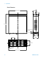
Specifications
Product Dimensions
64.6 mm
(2.54 in)
425.6 mm (16.76 in)
68.2 mm
(2.68 in)
367.7 mm (14.48 in)
M4.0 x 0.7 Thread
4 Places
22.4 mm (0.88 in)
2X 88.85 mm
(3.50 in)
74.26 mm
(2.92 in)
128.8 mm
(5.07 in)
2X 93.6 mm (3.68 in)
5.5 mm (0.22 in) SQ
M3.5 x 0.6 Thread
4 Places
404.0 mm (15.90 in)
36
34980A Service Guide
2
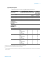
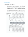
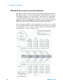
Specifications
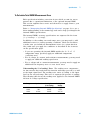
To Calculate Total DMM Measurement Error
Each specification includes correction factors which account for errors
present due to operational limitations of the optional internal DMM.
This section explains these errors and shows how to apply them to your
measurements.
Refer to “Interpreting Internal DMM Specifications" on page 39, to get a
better understanding of the terminology used and to help you interpret the
internal DMM’s specifications.
The internal DMM’s accuracy specifications are expressed in the form:
(% of reading + % of range).
In addition to the reading error and range error, you may need to add
additional errors for certain operating conditions. Check the list below
to make sure you include all measurement errors for a given function.
Also, make sure you apply the conditions as described in the footnotes
on the specification pages.
• If you are operating the internal DMM outside the 23 °C ± 5 °C
temperature range specified, apply an additional temperature
coefficient error.
• For dc voltage, dc current, and resistance measurements, you may need
to apply an additional reading speed error.
• For ac voltage and ac current measurements, you may need to apply an
additional low frequency error or crest factor error.
Understanding the “% of reading“ Error The reading error compensates
for inaccuracies that result from the function and range you select, as well
as the input signal level. The reading error varies according to the input
level on the selected range. This error is expressed in percent of reading.
The following table shows the reading error applied to the internal DMM’s
24- hour dc voltage specification.
34980A Service Guide
Range
Input Level
Reading Error
(% of reading)
Reading Error
Voltage
10 Vdc
10 Vdc
10 Vdc
10 Vdc
1 Vdc
0.1 Vdc
0.0015
0.0015
0.0015
150 V
15V
1.5 V
37
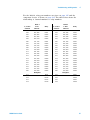
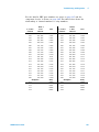
2
Specifications
Understanding the “% of range“ Error The range error compensates for
inaccuracies that result from the function and range you select. The range
error contributes a constant error, expressed as a percent of range,
independent of the input signal level. The following table shows the range
error applied to the DMM’s 24- hour dc voltage specification.
Range
Input Level
Range Error
(% of range)
Range Error voltage
10 Vdc
10 Vdc
10 Vdc
10 Vdc
1 Vdc
0.1 Vdc
0.0004
0.0004
0.0004
40 V
40 V
40 V
Total Measurement Error To compute the total measurement error, add
the reading error and range error. You can then convert the total
measurement error to a “percent of input” error or a “ppm (part- permillion) of input” error as shown below.
Total Measurement Error
% of input error = ------------------------------------------------------------- 100
Input Signal Level
Total Measurement Error
ppm of input error = ------------------------------------------------------------- 1 000 000
Input Signal Level
Example: Computing Total Measurement Error
Assume that a 5 Vdc signal is input to the DMM on the 10 Vdc range.
To compute the total measurement error using the 90- day accuracy
specification of ±(0.0020% of reading + 0.0005% of range).
Reading Error = 0.0020% x 5 Vdc = 100 V
Range error
= 0.0005% 10 Vdc = 50 V
Total Error
= 100 V + 50 V
38
= 150V
= 0.0030% of 5 Vdc
= 30 ppm of 5 Vdc
34980A Service Guide
2
Specifications
Interpreting Internal DMM Specifications
This section is provided to give you a better understanding of the
terminology used and will help you interpret the internal DMM’s
specifications.
Number of Digits and Overrange The “number of digits” specification is
the most fundamental, and sometimes, the most confusing characteristic of
a instrument. The number of digits is equal to the maximum number of
“9’s” the instrument can measure or display. This indicates the number of
full digits. Most instruments have the ability to overrange and add a
partial or “½” digit.
For example, the internal DMM can measure 9.99999 Vdc on the 10 V
range. This represents six full digits of resolution. The internal DMM can
also overrange on the 10 V range and measure up to a maximum of
12.00000 Vdc. This corresponds to a 6½- digit measurement with 20%
overrange capability.
Sensitivity Sensitivity is the minimum level that the instrument can
detect for a given measurement. Sensitivity defines the ability of the
instrument to respond to small changes in the input level. For example,
suppose you are monitoring a 1 mVdc signal and you want to adjust the
level to within ±1 V. To be able to respond to an adjustment this small,
this measurement would require a instrument with a sensitivity of at least
1 V. You could use a 6½- digit instrument if it has a 1 Vdc or smaller
range. You could also use a 4½- digit instrument with a 10 mVdc range.
For ac voltage and ac current measurements, note that the smallest value
that can be measured is different from the sensitivity. For the internal
DMM, these functions are specified to measure down to 1% of the selected
range. For example, the internal DMM can measure down to 1 mV on the
100 mV range.
Resolution Resolution is the numeric ratio of the maximum displayed
value divided by the minimum displayed value on a selected range.
Resolution is often expressed in percent, parts- per- million (ppm), counts,
or bits. For example, a 6½- digit instrument with 20% overrange capability
can display a measurement with up to 1,200,000 counts of resolution. This
corresponds to about 0.0001% (1 ppm) of full scale, or 21 bits including
the sign bit. All four specifications are equivalent.
34980A Service Guide
39
2
Specifications
Accuracy Accuracy is a measure of the “exactness” to which the internal
DMM’s measurement uncertainty can be determined relative to the
calibration reference used. Absolute accuracy includes the Internal DMM’s
relative accuracy specification plus the known error of the calibration
reference relative to national standards (such as the U.S. National Institute
of Standards and Technology). To be meaningful, the accuracy
specifications must be accompanied with the conditions under which they
are valid. These conditions should include temperature, humidity, and
time.
There is no standard convention among instrument manufacturers for the
confidence limits at which specifications are set. The table below shows
the probability of non- conformance for each specification with the given
assumptions.
Specification Criteria
Mean ± 2 sigma
Mean ± 3 sigma
Probability of Failure
4.5%
0.3%
Variations in performance from reading to reading, and instrument to
instrument, decrease for increasing number of sigma for a given
specification. This means that you can achieve greater actual measurement
precision for a specific accuracy specification number.
The internal DDMM is designed and tested to meet performance better
than mean ±3 sigma of the published accuracy specifications.
24-Hour Accuracy The 24- hour accuracy specification indicates the
internal DMM’s relative accuracy over its full measurement range for short
time intervals and within a stable environment. Short- term accuracy is
usually specified for a 24- hour period and for a ±1°C temperature range.
90-Day and 1-Year Accuracy These long- term accuracy specifications are
valid for a 23°C ± 5°C temperature range. These specifications include the
initial calibration errors plus the internal DMM’s long- term drift errors.
Temperature Coefficients Accuracy is usually specified for a 23°C ± 5°C
temperature range. This is a common temperature range for many
operating environments. You must add additional temperature coefficient
errors to the accuracy specification if you are operating the instrument
outside a 23°C ± 5°C temperature range (the specification is per °C).
40
34980A Service Guide
Specifications
2
Configuring for Highest Accuracy Measurements
The measurement configurations shown below assume that the internal
DMM is in its Factory Reset state. It is also assumed that manual ranging
is enabled to ensure proper full scale range selection.
DC Voltage, DC Current, and Resistance Measurements:
• Set the resolution to 6 digits (you can use the 6 digits slow mode for
further noise reduction).
• Set the input resistance to greater than 10 G (for the 100 mV, 1 V,
and 10 V ranges) for the best dc voltage accuracy.
• Use 4- wire ohms and enable offset compensation for the best resistance
accuracy.
AC Voltage and AC Current Measurements:
Set the resolution to 6 digits.
• Select the slow ac filter (3 Hz to 300 kHz).
Frequency and Period Measurements:
Set the resolution to 6 digits.
34980A Service Guide
41
2
42
Specifications
34980A Service Guide
Agilent 34980A Multifunction Switch/Measure Unit
Service Guide
3
Calibration Procedures
Agilent Technologies Calibration Services 44
Calibration Interval 44
Adjustment is Recommended 44
Time Required for Calibration 45
Automating Calibration Procedures 45
Recommended Test Equipment 46
Calibration Security 47
Calibration Message 48
Calibration Count 48
Calibration Process 49
Aborting a Calibration in Progress 49
Performance Verification Tests 50
Input Connections 52
DMM Test Considerations 53
Internal DMM Verification Tests 53
Optional AC Performance Verification Tests 59
Internal DMM Adjustments 60
Gain Adjustment 61
Plug-in Module Test Considerations 65
34951A 4-Ch Isolated DAC Module 66
34952A Multifunction Module 71
Relay Plug-in Modules 73
Thermocouple Reference Junction 34921A (Optional) 75
Agilent Technologies
43
3
Calibration Procedures
Calibration Procedures
This manual contains procedures for verification of the instrument’s
performance and adjustment (calibration).
Closed-Case Electronic Calibration The instrument features closed- case
electronic calibration. No internal mechanical adjustments are required.
The instrument calculates correction factors based upon the input
reference value you set. The new correction factors are stored in
non- volatile memory until the next calibration adjustment is performed.
Non- volatile EEPROM calibration memory does not change when power
has been off or after a remote interface reset.
Agilent Technologies Calibration Services
Agilent Technologies offers calibration services at competitive prices.
When your instrument is due for calibration, contact your local Agilent
Service Center for recalibration. See “Types of Service Available" on
page 6 for information on contacting Agilent.
Calibration Interval
The instrument should be calibrated on a regular interval determined by
the measurement accuracy requirements of your application.
A 1- year interval is adequate for most applications. Accuracy
specifications are warranted only if adjustment is made at regular
calibration intervals. Accuracy specifications are not warranted beyond the
1- year calibration interval. Agilent does not recommend extending
calibration intervals beyond 2 years for any application.
Adjustment is Recommended
Specifications are only guaranteed within the period stated from the last
adjustment. Whatever calibration interval you select, Agilent recommends
that complete re- adjustment should always be performed at the calibration
interval. This will assure that the 34980A will remain within specification
for the next calibration interval. This criteria for re- adjustment provides
the best long- term stability.
Performance data measured during Performance Verification Tests does not
guarantee the instrument will remain within these limits unless the
adjustments are performed.
Use the Calibration Count feature (see page 48) to verify that all
adjustments have been performed.
44
34980A Service Guide
3
Calibration Procedures
Time Required for Calibration
The 34980A can be automatically calibrated under computer control.
With computer control you can perform the complete calibration procedure
and performance verification tests in less than 30 minutes once the
instrument is warmed- up (see “DMM Test Considerations" on page 53).
Automating Calibration Procedures
You can automate the complete verification and adjustment procedures
outlined in this manual. You can program the instrument configurations
specified for each test over the remote interface. You can then enter
readback verification data into a test program and compare the results to
the appropriate test limit values.
You must adjust the instrument using the remote interface. Adjustment
cannot be performed from the local front- panel. The instrument must be
unsecured prior to initiating the calibration procedure (see “Calibration
Security" on page 47).
For further information on programming the instrument, see Chapter 2 in
the 34980A User's Guide.
For information about errors that may occur during the calibration
procedure, see “Calibration Errors" on page 86.
34980A Service Guide
45
3
Calibration Procedures
Recommended Test Equipment
The test equipment recommended for the performance verification and
adjustment procedures is listed below. If the exact instrument is not
available, substitute calibration standards of equivalent accuracy.
A suggested alternate method would be to use the Agilent 3458A 8½- digit
Digital Multimeter to measure less accurate yet stable sources. The output
value measured from the source can be entered into the instrument as the
target calibration value.
Application
Recommended Equipment
Accuracy Requirements
Zero Calibration
DC Voltage
DC Current
Resistance
AC Voltage
AC Current
Frequency
None
Fluke 5700A
Fluke 5700A/ 5725A
Fluke 5700A
Fluke 5700A/ 5725A
Fluke 5700A/ 5725A
Agilent 33220A
4 -terminal all copper short
<1/5 instrument 24 hour spec
<1/5 instrument 24 hour spec
<1/5 instrument 24 hour spec
<1/5 instrument 24 hour spec
<1/5 instrument 24 hour spec
<1/5 instrument 24 hour spec
Analog Output 34951A
Internal DMM
<1/5 instrument 24 hour spec
Analog Output 34952A
Internal DMM
<1/5 instrument 24 hour spec
Thermocouple
Reference Junction
34921A with 34921T Only
J Type Calibrated
Thermocouple
Triple Point Cell
Relay contact resistance [1]
All switch modules
Agilent Y1131A
± 0.1 × C
± 0.001 resolution
[1] Optional test if not using relay cycle count.
46
34980A Service Guide
3
Calibration Procedures
Calibration Security
This feature allows you to enter a security code to prevent accidental or
unauthorized adjustments of the instrument. When you first receive your
instrument, it is secured. Before you can adjust the instrument, you must
unsecure it by entering the correct security code.
NOT E
If you forget your security code, you can disable the security feature by
following the procedure below.
• The security code is set to AT34980 when the instrument is shipped
from the factory. The security code is stored in non- volatile memory,
and does not change when power has been off, after a Factory Reset
(*RST command), or after an Instrument Preset (SYSTem:PRESet
command).
• The security code may contain up to 12 alphanumeric characters. The
first character must be a letter, but the remaining characters can be
letters, numbers, or an underscore ( _ ). You do not have to use all 12
characters but the first character must always be a letter.
• The 34951A 4 Channel DAC has two modes of adjustment, based upon
the setting of the calibration security feature. Additional details are
described in “34951A 4- Ch Isolated DAC Module" on page 66.
Use the CALibration:SECure:STATe <mode>,<code> command to secure
or unsecure the instrument. Refer to the 34980A Programmer's Reference
Help File for complete information.
To Unsecure the Instrument Without the Security Code To unsecure the
instrument without the correct security code, follow the steps below.
1 Turn off the instrument.
2 Press and hold the DMM (Measure) key and CANCEL key and turn on
the unit. You can release the keys when the unit has completed the
power on sequence.
3 Send the CALibration:SECure:STATe OFF,<code> command to the
instrument. You may use any valid sequence of characters for the
<code> value.
4 The unit is now unsecured for calibration.
5 Enter a new security code when calibration is complete. Be sure to
remember the new security code.
34980A Service Guide
47
3
Calibration Procedures
Calibration Message
The instrument allows you to store a message in calibration memory.
You may store a calibration message for the mainframe, the DMM, the
34951A 4- Ch Isolated DAC Module, and 34952A Multifunction Module.
For example, you can store such information as the date when the last
calibration was performed, the date when the next calibration is due, the
instrument’s serial number, or even the name and phone number of the
person to contact for a new calibration.
• You can record a calibration message only from the remote interface
and only when the instrument is unsecured. You can read the
calibration message whether the instrument is secured or unsecured.
• The calibration message may contain up to 40 characters.
• Remote Interface Commands:
CALibration:STRing <string>,{<slot>|MAINframe|DMM}
CALibration:STRing? {<slot>|MAINframe|DMM}
Calibration Count
You can query the mainframe, the DMM, the 34951A 4- Ch Isolated DAC
Module, and 34952A Multifunction Module to determine how many
calibrations have been performed. Note that your instrument was
calibrated before it left the factory. When you receive your instrument,
be sure to read the count to determine its initial value.
• The calibration count increments up to a maximum of 232 after which it
rolls over to “0”. Since the value increments by one for each calibration
point, a complete calibration may increase the value by many counts.
• The calibration count is also incremented with calibrations of the
34951A 4- Ch DAC and DAC channels on the 34952A multifunction
module.
• Remote Interface Command:
CALibration:COUNt? {<slot>|MAINframe|DMM}
48
34980A Service Guide
Calibration Procedures
3
Calibration Process
The following general procedure is the recommended method to complete a
full instrument calibration.
1 Read “DMM Test Considerations" on page 53 and “Plug- in Module Test
Considerations" on page 65.
2 Perform the verification tests to characterize the instrument (incoming
data).
3 Unsecure the instrument for calibration (“Calibration Security" on
page 47).
4 Perform the DMM adjustment procedures (“Internal DMM
Adjustments" on page 60).
5 Perform the DAC adjustment procedures if either the 34951A (“34951A
4- Ch Isolated DAC Module" on page 66) or 34952A (“34952A
Multifunction Module" on page 71) is installed.
6 Secure the instrument against calibration.
7 Note the new security code and calibration count in the instrument’s
maintenance records.
NOT E
The 34951A 4-Ch Isolated DAC is intended to be adjusted frequently to
compensate for changes in the module’s environment. These
adjustments can be made either volatile or non-volatile. See page 66 for
details.
Aborting a Calibration in Progress
Sometimes it may be necessary to abort a calibration after the procedure
has already been initiated. You can abort a calibration at any time on any
module by turning off the power. You can abort a calibration on the
internal DMM or the 34951A 4- Ch Isolated DAC by issuing a remote
interface device clear message. You can abort a calibration on the 34952A
Multifunction Module by sending the CALibration:ABORt command.
CAUTION
34980A Service Guide
If you abort a calibration in progress when the instrument is attempting
to write new calibration constants to EEPROM, you may lose all
calibration constants for the function. Typically, upon re-applying
power, the instrument will report error 705 Cal:Aborted. You may also
generate errors 740 through 746. If this occurs, you should not use the
instrument until a complete re-adjustment has been performed. For a list
of calibration error numbers, see page 86.
49
3
Calibration Procedures
Performance Verification Tests
Use the Performance verification Tests to verify the measurement
performance of the instrument. The performance verification tests use the
instrument’s specifications listed in Chapter 2 Specifications in this
manual.
You can perform four different levels of performance verification tests:
• Self- Test A series of internal verification tests that give a high
confidence that the instrument is operational.
• Quick Verification A combination of the internal self- tests and selected
verification tests.
• Performance Verification Tests An extensive set of tests that are
recommended as an acceptance test when you first receive the
instrument or after performing adjustments.
• Optional Verification Tests Tests not performed with every calibration.
Perform these tests to verify additional specifications or functions of
the instrument.
Self-Test
A brief power- on self- test occurs automatically whenever you turn on the
instrument. This limited test assures that the instrument is capable of
operation and also checks the plug- in modules for basic operation.
• During the self- test all display segments and annunciators are lit.
• If the self- test fails, the ERROR annunciator turns on. Read any errors
using the front panel View menu, or use the SYSTem:ERRor? command
query from the remote interface. If repair is required, contact an
Agilent Service Center.
• If all tests pass, you have a high confidence (~90%) that the instrument
is operational.
• You can initiate a more complete self test by sending the *TST?
command to the instrument. This command returns a “+0” if all the
self- tests pass, or a “+1” if a failure occurred. Depending upon the
number and type of modules installed, this command may take up to
2½ minutes to complete. You may need to set an appropriate interface
time- out value.
50
34980A Service Guide
Calibration Procedures
3
Quick Performance Check
The quick performance check is a combination of internal self- test and an
abbreviated performance test (specified by the letter Q in the performance
verification tests). This test provides a simple method to achieve high
confidence in the instrument’s ability to functionally operate and meet
specifications. These tests represent the absolute minimum set of
performance checks recommended following any service activity.
Auditing the instrument’s performance for the quick check points
(designated by a Q) verifies performance for “normal” accuracy drift
mechanisms. This test does not check for abnormal component failures.
To perform the quick performance check, do the following:
• Perform a self- test as described on page 50.
• Perform only the performance verification tests indicated with the
letter Q.
If the instrument fails the quick performance check, adjustment or repair
is required.
Performance Verification Tests
The performance verification tests are recommended as acceptance tests
when you first receive the instrument. The acceptance test results should
be compared against the 90 day test limits. You should use the 24- hour
test limits only for verification within 24 hours after performing the
adjustment procedure. After acceptance, you should repeat the
performance verification tests at every calibration interval.
If the instrument fails performance verification, adjustment or repair is
required.
Adjustment is recommended at every calibration interval. If adjustment is
not made, you must guard band, using no more than 80% of the
specifications, as the verification limits.
34980A Service Guide
51
3
Calibration Procedures
Internal DMM
Input Connections
Test connections to the internal DMM are best accomplished using the rear
panel Analog Bus connector (ABus). You may need to remove the cover for
access to this connector. A test fixture can be constructed using a
standard DB9 male connector, some shielded twisted pair PTFE insulated
cables, and appropriate connectors for the calibrator output
you are using.
You may also use one of the multiplexer modules to connect the calibrator
output to the DMM. If you use a multiplexer module, you must take into
account any additional relay contacts and resistances in the measurement
path. To do this, use the switch/measure model to set up the DMM and
switches, not the scan model. For example, send:
conf:fres 100;:rout:clos (@1001,1021,1911,1922)
read? (should return something close to zero)
cal:val 0
cal?
In this manual, the direct ABus connection is the one described.
Connections for the ABus connector are shown below.
NOT E
Use shielded twisted pair PTFE insulated cables to reduce settling and
noise errors. Connect the shield to the source LO output.
PTFE is a registered trademark of E.I. du Pont de Nemours and Company.
52
34980A Service Guide
3
Calibration Procedures
DMM Test Considerations
Errors may be induced by ac signals present on the input leads during a
self- test. Long test leads can also act as an antenna causing pick- up of ac
signals.
For optimum performance, all procedures should comply with the
following recommendations:
• Assure that the calibration ambient temperature is stable and
between 18 °C and 28 °C. Ideally the calibration should be
performed at 23 °C ±1 °C.
• Assure ambient relative humidity is less than 80%.
• Allow a 1.5- hour warm- up period with a copper short connecting pins
3, 4, 8, and 9 of the ABus connector. Connector pinout is shown in the
figure on page 52.
• Use shielded twisted pair PTFE insulated cables to reduce settling and
noise errors. Keep the input cables as short as possible.
• Connect the input cable shield to the source LO output. Except where
noted in the procedures, connect the calibrator LO source to earth
ground.
• Either remove all modules from the mainframe, or reset the modules to
ensure no module is connected to the backplane ABus.
Because the instrument is capable of making highly accurate
measurements, you must take special care to ensure that the calibration
standards and test procedures used do not introduce additional errors.
Ideally, the standards used to verify and adjust the instrument should be
an order of magnitude more accurate than each instrument range full
scale error specification.
For the dc voltage, dc current, and resistance gain verification
measurements, you should take care to ensure the calibrator’s “0” output
is correct. If necessary, the measurements can be referenced to the
calibrator’s “0” output using Mx + B scaling (see Chapter 2 in the 34980A
User's Guide). You will need to set the offset for each range of the
measuring function being verified.
34980A Service Guide
53
3
Calibration Procedures
Internal DMM Verification Tests
Zero Offset Verification
This procedure is used to check the zero offset performance of the
internal DMM. Verification checks are only performed for those functions
and ranges with unique offset calibration constants. Measurements are
checked for each function and range as described in the procedure on the
next page.
54
34980A Service Guide
3
Calibration Procedures
Zero Offset Verification Procedure
1 Make sure you have read “DMM Test Considerations" on page 53.
2 Short all the inputs on the input test connector (see page 52).
Leave the Current input open. Connect the shorts as close to the input
connector as possible.
3 Select each function and range in the order shown in the table below.
Make a measurement and return the result. Compare measurement
results to the appropriate test limits shown in the table.
Input
Open
Function[1]
DC Current
Range
Quick
Check
10 mA
24 hour
90 day
1 year
± 1 µA
± 2 µA
± 2 µA
± 4 µA
± 5 µA
± 5 µA
Open
100 mA
Open
1A
± 60 µA
± 100 µA
± 100 µA
100 mV
± 3.5 µV
± 4 µV
± 4 µV
Short
1V
± 6 µV
± 7 µV
± 7 µV
Short
10 V
± 40 µV
± 50 µV
± 50 µV
Short
100 V
± 600 µV
± 600 µV
± 600 µV
Short
300 V
± 6 mV
± 9 mV
± 9 mV
100
± 3.5 m
± 4 m
± 4 m
1 k
± 6 m
± 10 m
± 10 m
± 50 m
± 100 m
± 100 m
Short
Short
DC Volts
2-Wire Ohms
and 4-Wire
Ohms
Q
Error from Nominal
Q
[2]
Short
Short
10 k
Q
Short
100 k
± 500 m
±1
±1
Short
1 M
± 10
± 10
± 10
Short
10 M
± 100
± 100
± 100
Short
100 M
± 10 k
± 10 k
± 10 k
[1] Select 6½ digit resolution.
[2] For 2-wire ohms using a multiplexer for the input connections, an additional 4 of error for the relay
contacts must be added.
Q: Quick performance verification test points.
NOT E
34980A Service Guide
Zero offset calibration using a multifunction calibrator is NOT
recommended. The calibrator and cabling offset can be large and
unstable causing poor offset calibration of the internal DMM.
55
3
Calibration Procedures
Gain Verification
This procedure is used to check the “full scale” reading accuracy of the
internal DMM. Verification checks are performed only for those functions
and ranges with unique gain calibration constants.
DC VOLTS, Resistance, and DC CURRENT Gain Verification Test
1 Make sure you have read “DMM Test Considerations" on page 53.
2 Select each function and range in the order shown below. Provide the
input shown in the table below.
3 Make a measurement and return the result. Compare measurement
results to the appropriate test limits shown in the table. (Be certain to
allow for appropriate source settling when using the Fluke 5700A.)
Input
Function[1]
100 mV
Error from Nominal
24 hour
90 day
1 year
100 mV
± 6.5 µV
± 8 µV
± 9 µV
1V
1V
± 26 µV
± 37 µV
± 47 µV
10 V
10 V
Q
± 190 µV
± 250 µV
± 400 µV
100 V
100 V
Q
± 2.6 mV
± 4.1 mV
± 5.1 mV
300 V
300 V
± 12 mV
± 19.5 mV
± 22.5 mV
100
± 6.5 m
± 12 m
± 14 m
± 26 m
± 90 m
± 110 m
100
1 k
DC Volts
Range
Quick
Check
2-Wire Ohms
4-Wire
Ohms
[2] and
1 k
Q
10 k
10 k
± 250 m
± 900 m
± 1.1
100 k
100 k
± 2.5
±9
± 11
1 M
1 M
± 30
± 90
± 110
10 M
10 M
± 1.6 k
± 2.1 k
± 4.1 k
100 M
100 M
± 310 k
± 810 k
± 810 k
10 mA
± 1.5 µA
± 5 µA
± 7 µA
± 14 µA
± 35 µA
± 55 µA
± 560 µA
± 900 µA
± 1.1 mA
10 mA
DC Current
100 mA
100 mA
1A
1A
Q
Q
[1] Select 6 ½ digit resolution.
[2] The 2-wire ohms resistance verification test is optional (see “Gain Adjustment Considerations" on
page 61). For 2-wire ohms using a multiplexer for the input connections, an additional 4 of error for the
relay contacts must be added. Add a 1-second channel delay when using Fluke 5700 in 2-wire
compensated mode. This avoids response time issues with 2-wire compensation when 34980A’s current
source contains a pulse.
[3] Verify only, no adjustment required.
Q: Quick performance verification test points.
56
34980A Service Guide
Calibration Procedures
3
AC VOLTS Gain Verification Test
AC Volts
Configuration:
CONFigure[:VOLTage]:AC
LF 3 HZ:SLOW
[SENSe:]VOLTage:AC:BANDwidth 3
1 Make sure you have read “DMM Test Considerations" on page 53.
2 Set the AC VOLTS function and the 3 Hz input filter. With the slow
filter selected, each measurement takes 7 seconds to complete.
3 Select each range in the order shown below. Provide the indicated input
voltage and frequency. Compare measurement results to the appropriate
test limits shown in the table. (Be certain to allow for appropriate
source settling.)
Input
Vrms
Frequency
Range
100 mV
1 kHz
100 mV
50 kHz
1V
1 kHz
1V
50 kHz
10 V
1 kHz
10 V
50 kHz
10 V
10 Hz
10 mV [1]
1 kHz
100 mV
100 V
1 kHz
100 V
100 V
50 kHz
300 V
1 kHz
300 V[2]
50 kHz
Quick
Check
100 mV
Q
1
10 V
Q
300 V
Q
Error from Nominal
24 hour
90 day
1 year
± 70 µV
± 90 µV
± 100 µV
± 150 µV
± 160 µV
± 170 µV
± 700 µV
± 900 µV
± 1 mV
± 1.5 mV
± 1.6 mV
± 1.7 mV
± 7 mV
± 9 mV
± 10 mV
± 15 mV
± 16 mV
± 17 mV
± 7 mV
± 9 mV
± 10 mV
± 34 µV
± 45 µV
± 46 µV
± 70 mV
± 90 mV
± 100 mV
± 150 mV
± 160 mV ± 170 mV
± 270 mV
± 390 mV ± 420 mV
± 600 mV
± 690 mV ± 720 mV
[1] For this test, isolate the calibrator’s output from earth ground to prevent ground noise affecting the
reading.
[2] Some calibrators may have difficulty driving the internal DMM and cable load at this V-Hz output. Use
short, low capacitance cable to reduce calibration loading. Verification can be performed at >195 Vrms.
New test limits can be computed from the accuracy specification shown in the data sheet for the actual test
conditions used.
Q: Quick performance verification test points.
34980A Service Guide
57
3
Calibration Procedures
The 50 kHz ac voltage test points may fail performance verification if
the DMM internal shields have been removed and reinstalled. See “Gain
Adjustment" on page 61 for further information on how to recalibrate
the ac voltage function.
NOT E
AC CURRENT Gain Verification Test
AC Current
Configuration:
CONFigure:CURRent:AC
LF 3 HZ:SLOW
[SENSe:]CURRent:AC:BANDwidth 3
1 Make sure you have read “DMM Test Considerations" on page 53.
2 Set the AC CURRENT function and the 3 Hz input filter. With the slow
filter selected, each measurement takes 7 seconds to complete.
3 Select each range in the order shown below. Provide the input current
and frequency indicated. Compare measurement results to the
appropriate test limits shown in the table. (Be certain to allow for
appropriate source settling.)
Input
Current
Frequency
Range
1 kHz
10 mA
1 kHz
100 mA
10 mA
1 kHz
1A [1]
1 kHz
10 mA [1]
100 mA
[1]
Quick
Check
Error from Nominal
24 hour
90 day
1 year
± 14 µA
± 14 µA
± 14 µA
± 600 µA
± 600 µA
± 600 µA
1A
± 1.41 mA
± 1.41 mA
± 1.41 mA
1A
± 1.4 mA
± 1.4 mA
± 1.4 mA
Q
[1] Verify only, no adjustment.
Q: Quick performance verification test points.
58
34980A Service Guide
3
Calibration Procedures
Frequency Gain Verification Test
Configuration:
Frequency
6½ digits
[SENSe:]FREQuency:APERture 1
1 Make sure you have read “DMM Test Considerations" on page 53.
2 Select the FREQUENCY function and set 6½ digits.
3 Select each range in the order shown below. Provide the input voltage
and frequency indicated. Compare measurement results to the
appropriate test limits shown in the table. (Be certain to allow for
appropriate source settling.)
Input
Voltage
10 mV
1V
[1]
Frequency
Range
100 Hz
100 mV
100 kHz
1V
Quick
Check
Q
Error from Nominal
24 hour
90 day
1 year
± 0.06 Hz
± 0.1 Hz
± 0.1 Hz
± 6 Hz
± 10 Hz
± 10 Hz
[1] Verify only, No adjustment. For this test, isolate the calibrator’s output from earth ground.
Q: Quick performance verification test points.
34980A Service Guide
59
3
Calibration Procedures
Optional AC Performance Verification Tests
These tests are not intended to be performed with every calibration. They
are provided as an aid for verifying additional instrument specifications.
There are no adjustments for these tests; they are provided for
performance verification only.
AC Volts
Configuration:
CONFigure[:VOLTage]:AC
LF 3 HZ:SLOW
[SENSe:]VOLTage:AC:BANDwidth 3
1 Make sure you have read “DMM Test Considerations" on page 53.
2 Select the AC Volts function and the 3 Hz filter.
3 Select each range in the order shown below. Provide the input voltage
and frequency indicated. Compare measurement results to the
appropriate test limits shown in the table below. (Be certain to allow
for appropriate source settling.)
Input
Voltage
60
Frequenc
y
Error from Nominal
Range
24 hour
90 day
1 year
1V
20 Hz
1V
± 700 µV
± 900 µV
± 1 mV
1V
20 kHz
1V
± 700 µV
± 900 µV
± 1 mV
1V
100 kHz
1V
± 6.3 mV
± 6.8 mV
± 6.8 mV
1V
300 kHz
1V
± 45 mV
± 45 mV
± 45 mV
10 V
1 kHz
10 V
± 7 mV
± 9 mV
± 10 mV
1V
1 kHz
10 V
± 3.4 mV
± 4.5 mV
± 4.6 mV
100 mV
1 kHz
10 V
± 13 mV
± 14 mV
± 14 mV
34980A Service Guide
Calibration Procedures
3
Internal DMM Adjustments
You will need a test input fixture to adjust the internal DMM
(see page 52).
Zero Adjustment
Each time you perform a zero adjustment, the Internal DMM stores a new
set of offset correction constants for every measurement function and
range. The Internal DMM will sequence through all required functions and
ranges automatically and store new zero offset calibration constants. All
offset corrections are determined automatically. You may not correct a
single range or function without re- entering ALL zero offset correction
constants automatically. This feature is intended to save calibration time
and improve zero calibration consistency.
NOT E
Never turn off the Internal DMM during Zero Adjustment. This may
cause ALL calibration memory to be lost.
Zero Adjustment Procedure
The zero adjustment procedure takes about 5 minutes to complete. Be sure
to allow the instrument to warm up for 2 hours before performing the
adjustments.
Follow the steps outlined below. Review “DMM Test Considerations" on
page 53 before beginning this test.
1 This procedure will use the copper shorts installed on input test
connector. Leave the Current input connection open.
2 Set the DC VOLTS function.
3 Send the value 0.000000 to the instrument using the
CALibration:VALue 0.000000 command.
4 Calibrate the instrument using the CALibration? command.
5 Perform the “Zero Offset Verification" on page 53 to check zero
calibration results.
34980A Service Guide
61
3
Calibration Procedures
Gain Adjustment
The Internal DMM stores a single new gain correction constant each time
this procedure is followed. The gain constant is computed from the
calibration value entered for the calibration command and from
measurements made automatically during the adjustment procedure.
Most measuring functions and ranges have gain adjustment procedures.
Only the 100 M range does not have gain calibration procedures.
Adjustments for each function should be performed ONLY in the order
shown in the performance verification table. See “Performance Verification
Tests" on page 50 for the tables used for gain adjustments.
Gain Adjustment Considerations
• The zero adjustment procedure must have been recently performed
prior to beginning any gain adjustment procedures.
• The optional –10 Vdc adjustment should be performed only after
servicing the Internal DMM’s a- to- d converter.
• When performing a 4- wire ohms gain adjustment, a new gain correction
constant is also stored for the corresponding 2- wire ohms measurement
range. If desired, the 2- wire gain can be adjusted separately after the
4- wire ohms gain calibration is completed. If the 2- wire Ohms gain is
adjusted separately, the 2- wire Ohms function will not meet
specifications when offset compensated Ohms is used.
• During the ac voltage gain adjustments, some of the dc voltage gain
constants are used. Perform the dc voltage gain calibration before the
ac voltage gain calibration.
NOT E
62
Never turn off the instrument during a Gain Adjustment. This may cause
calibration memory for the present function to be lost.
34980A Service Guide
Calibration Procedures
3
Valid Gain Adjustment Input Values
Gain adjustment can be accomplished using the following input values.
Function
DC VOLTS
Range
Valid Calibration
Input Values
100 mV to 100 V
0.9 to 1.1 x Full Scale
300 V
250 V to 303 V
OHMS, OHMS 4W
100 to 10 M
0.9 to 1.1 x Full Scale
DC CURRENT
10 mA to 1 A
0.9 to 1.1 x Full Scale
AC VOLTS [1]
10 mV to 100 V
0.9 to 1.1 x Full Scale
300 V
95 V to 303 V
AC CURRENT
1A
9 mA to 11 mA
FREQUENCY
Any
Any Input > 100 mV
rms, 1 kHz –100 kHz
[1] Valid frequencies are as follows: 1 kHz ± 10% for the 1 kHz calibration,
45 kHz–100 kHz for the 50 kHz calibration,
and 10 Hz ± 10% for the 10 Hz calibration.
34980A Service Guide
63
3
Calibration Procedures
Gain Adjustment Procedure
Adjustment for each function should be performed only in the order
shown in the performance verification table. The performance verification
tables used for gain adjustments start on page 55.
Review the “DMM Test Considerations" on page 53 and “Gain Adjustment
Considerations" on page 61 sections before beginning this test.
Configuration: DC functions — 6½ digits
AC functions — LF 3 HZ:SLOW
1 Configure each function and range shown in the gain verification tables
(starting on page 55).
2 Apply the input signal shown in the “Input” column of the appropriate
verification table.
.
NOT E
Always complete tests in the same order as shown in the appropriate
verification table.
3 Send the actual input value to the instrument using the
CALibration:VALue <value> command.
4 Calibrate the instrument using the CALibration? command.
5 Perform the appropriate Gain Verification Test to check the calibration
results.
6 Repeat steps 1 through 5 for each gain verification test point shown in
the tables.
NOT E
64
Each range in the gain adjustment procedure takes less than 20 seconds
to complete.
34980A Service Guide
Calibration Procedures
3
–10 Vdc Adjustment Procedure (Optional)
The –10 Vdc calibration electronically enhances the Internal DMM’s a- to- d
converter linearity characteristic. This adjustment should ONLY be
performed after servicing the A- to- D converter or replacement of the
calibration RAM.
You will need an input test connector as described in “Input
Connections" on page 52.
1 If a zero calibration has not been performed recently, perform one
before beginning this procedure (see page 60).
2 Configure the instrument as follows:
DC VOLTS
10 V range
6½ digits
INTEG 100 PLC
INPUT R > 10 G
[SENSe:]VOLTage[:DC]:RANGe 10
[SENSe:]VOLTage[:DC]:NPLC 100
[SENSe:]VOLTage[:DC]:IMP:AUTO ON
3 Measure and note the voltage offset present at the end of the
measurement cable by shorting the ends of the cable. Be sure to use a
copper wire and allow enough time for the residual thermal offset to
stabilize (usually about 1 minute).
4 Connect the input cable to the calibrator output and set the calibrator
to output +10V. Allow enough settling time for any thermal offset
voltages to stabilize (usually about 1 minute).
5 Perform a +10V dc gain calibration.
6 Send an adjustment to the instrument. The adjustment value is the sum
of the calibrator output and the measured offset (from step 3). For
example, if the calibrator output is 10.001 volts and the measured offset
is 10 µV, send the value +10.001010 volts. When the adjustment finishes,
verify that new readings fall within ±20 µV of the calibrator output plus
the offset.
7 Reverse the cable connections to the calibrator to create a –10 Vdc
voltage standard. You must physically reverse the cables. DO NOT
switch the output polarity of the calibrator.
8 Perform a –10V DC gain calibration. Be sure to allow time for thermal
offsets to stabilize (usually about 1 minute).
9 Send an adjustment to the instrument. The adjustment value is the sum
of the calibrator output and the measured offset (from step 3). Using
the previous example values, enter 10 µV minus 10.001 volts or
–10.000990 volts.
10 When the adjustment finishes, verify that new readings fall
within ± 30 µV of the calibrator output minus the offset.
34980A Service Guide
65
3
Calibration Procedures
Plug-in Modules
Plug-in Module Test Considerations
For optimum performance, all test procedures should comply with the
following recommendations:
• Assure that the calibration ambient temperature is stable and
between 18 °C and 28 °C. Ideally the calibration should be
performed at 23 °C ± 1 °C.
• Assure ambient relative humidity is less than 80%.
• Install the plug- in module and allow a 1 hour warm- up period before
verification or adjustment.
• Use shielded twisted pair PTFE insulated cables to reduce settling and
noise errors. Keep the input cables as short as possible.
• Remove all user wiring and connections from the plug- in modules
before verification or adjustment.
• Use 4- wire Ohms measurement techniques for checking relay contact
resistance. Check directly at the terminals where possible.
66
34980A Service Guide
3
Calibration Procedures
34951A 4-Ch Isolated DAC Module
Each isolated DAC output channel can be measured and adjusted using the
internal DMM. The Internal DMM is recommended because it compensates
for ambient temperature.
The 34951A features “auto- calibration”. Upon receipt of the calibration
command, all channels on the DAC are adjusted using the internal DMM.
Additionally you may adjust ALL 34951A modules installed in the
instrument with one command. The adjustments require approximately
one minute per module.
NOT E
The 34951A 4-Ch Isolated DAC is intended to be adjusted frequently to
compensate for changes in the module’s environment (changes in
ambient temperature, changing the mainframe slot used, adding or
removing modules to a system). These adjustments can be made either
volatile or non-volatile as described below. The adjustment procedure is
given beginning on page 70.
There are two ways to adjust the DACs, depending upon the state of
calibration security (see “Calibration Security" on page 47).
• If the instrument is secured for calibration when the adjustment is
begun, the adjustments are considered volatile. All adjustments are
discarded when power is cycled. This provides an easy means to make
immediate temperature- compensated adjustments to the DAC outputs
without overwriting stored calibration constants.
When this type of adjustment is made, the calibration count
(see page 48) is not advanced.
• If the instrument is unsecured for calibration, the adjustments are
written to non- volatile calibration memory. The calibration count
(see page 48) is advanced.
34980A Service Guide
67
3
Calibration Procedures
34951A Verification
Test Connections The DAC outputs can be measured using an external
voltmeter, or using a test fixture such as the one shown below, with the
internal DMM via the ABus connector on the instrument’s rear panel.
68
34980A Service Guide
Calibration Procedures
3
Analog Output Verification Test This procedure is used to check the
calibration of the analog outputs on the 34951A 4- channel DAC Module.
Verification checks are performed only for those output values with unique
calibration constants.
1 Using the input test connector described on page 67, leave the current
input terminal open. Set the DMM to the 100 mA range. Make and
record a current measurement. This value will be used as an offset
value during the output current zero verification.
2 Make voltage measurement connections to channel 1 of the module.
3 Set each output voltage value in the table below and make a
measurement. Compare measurement results to the appropriate test
limits shown in the table.
NOT E
It is not necessary to test the voltage output at the full rated 10 mA load.
If you test the output using a load, connect the sense terminals.
4 Make current measurement connections to channel 1 of the module. Set
the DMM to the 100 mA range.
5 Set each output current value in the table below and make a
measurement. Compare measurement results to the appropriate test
limits shown in the table. When measuring the 0 mA output value,
apply the offset value from step 1 to the measured value.
6 Repeat steps 2 through 5 for channels 2, 3 and 4.
7 Remove the input test connector.
34980A Service Guide
69
3
Calibration Procedures
.
Output Voltage
Quick
Check
16 V
Q
Error from
Nominal (90 day)
± 11 mV
12 V
± 9 mV
10 V
± 8 mV
8V
± 7 mV
4V
± 5 mV
0V
Q
± 3 mV
-4V
± 5 mV
-8 V
± 7 mV
-10 V
± 8 mV
-12 V
± 9 mV
-16 V
Q
Output Current
Quick
Check
20 mA
Q
± 11 mV
Error from
Nominal (90 day)
± 23 A
15 mA
± 18.5 A
10 mA
± 14 A
5 mA
± 9.5 A
0 mA [1]
Q
± 5 A
-5 mA
± 9.5 A
-10 mA
± 14 A
-15 mA
± 18.5 A
-20 mA
Q
± 23 A
[1] Apply a measured “0” offset to this measurement.
70
34980A Service Guide
3
Calibration Procedures
Analog Output Adjustment
Install the 34951A module in the mainframe and allow a 1 hour warm- up
before performing these procedures.
This adjustment procedure sets a zero adjustment and a gain adjustment
constant for each DAC output. You must perform all the adjustments on
one analog output channel before adjusting the other analog output
channel.
1 Install the module(s) in the instrument. Remove any inputs from the
ABus connector.
CAUTION
Remove any ABus connector before performing this procedure.
2 Set the calibration security for the adjustment mode you desire, see
page 66.
3 Send the CALibration:MODule? <slot> command to begin the
auto- calibration procedure for all channels on the module in <slot>.
You may use the CALibration:MODule? ALL command to perform the
auto- calibration on all channels for all modules installed in the
mainframe. The complete procedure may take up to 1 minute per
module. Be sure to set the remote command time- out value
appropriately.
4 The command returns a value of “+0” if the calibration is successful.
A returned value of “+1” indicates a calibration failure.
NOT E
34980A Service Guide
Following the auto-calibration procedure, the DMM is left in its reset
state (DCV).
71
3
Calibration Procedures
34952A Multifunction Module
The only calibration constants are for the two DAC outputs on the 34952A
Multifunction Module. These outputs can be measured using an external
voltmeter, or with a test fixture such as the one shown below, using the
internal DMM via the ABus connector on the instrument’s rear panel.
34952A Verification
Analog Output Verification Test This procedure is used to check the
calibration of the analog outputs on the 34952A Multifunction Module.
Verification checks are performed only for those output values with unique
calibration constants.
1 Use the internal DMM to measure the output of each channel. You will
need to physically move the input connections on the 34952A module to
channel 6 and then channel 7.
2 For each analog output (channel 6 and channel 7), set each output
value in the table on the next page. Compare measurement results to
the appropriate test limits shown in the table.
NOT E
72
It is not necessary to test the voltage output at the full rated 10 mA load.
34980A Service Guide
3
Calibration Procedures
Output Voltage
Quick Check
10 V
Q
± 45 mV
0V
Q
± 20 mV
-10 V
Error from
Nominal (1 year)
± 45 mV
Analog Output Adjustment
Install the 34952A module in the mainframe and allow a
1 hour warm- up before performing these procedures.
This adjustment procedure sets a zero adjustment and a gain adjustment
constant for each DAC output. You must perform all the adjustments on
one analog output channel before adjusting the other analog output
channel.
1 Install the module(s) in the instrument.
2 Unsecure the instrument for calibration (see page 47).
3 Connect channel 6 DAC output to the DMM input. Set the DMM to
measure DC volts.
4 The calibration procedure makes two adjustments per channel.
After sending the first command, measure the module output. Send the
measured value to the module and advance to the next point.
This procedure is summarized as follows:
a Send the following command to begin the procedure.
CALibration:BEGin:VOLTage 1,(@<channel>)
b Measure the module output.
c
Send the measured value to the module with the following command:
CALibration:POINt? <value>
d The command returns a “+1” to indicate it is ready for the next
point.
e
Measure the module output.
f
Send the measured value to the module with the following command:
CALibration:POINt? <value>
g The command returns a “+0” to indicate the calibration on the
channel is completed.
5 Repeat steps 3 and 4 for channel 7.
34980A Service Guide
73
3
Calibration Procedures
Relay Plug-in Modules
There are two methods you can use to verify relays:
• Read the relay cycle count.
• Measure the relay contact resistance.
Relay Cycle Count
The instrument has a Relay Maintenance System to help you predict relay
end- of- life. The instrument counts the cycles on each relay in the
instrument and stores the total count in non- volatile memory on each
switch module. You can use this feature on any of the relay modules and
the internal DMM.
• In addition to the channel relays, you can also query the count on
backplane relays and bank relays. Note that you cannot control the
state of these relays from the front panel but you can query the count.
• You can also query the state of the six relays on the internal DMM.
These relays open or close when a function or range is changed on a
module.
• You can reset the count but the instrument must be unsecured (see
“Calibration Security" on page 47 to unsecure the instrument).
• The 34923A, 34924A, and 34933A modules can be configured for 2- wire
(differential) or 1- wire (single ended) measurements. Since two coils are
required to drive each channel relay in the 2- wire mode, the module
stores the cycle count for each coil and returns the greater of the two.
To determine the cycle count for each coil, reconfigure the module for
the 1- wire mode (a power cycle is required) and query the count.
• The FET switches on the 34925A FET Multiplexer module have an
infinite life when used under normal operating conditions. Therefore,
the cycle count is not recorded and this command always returns “0”
(will not generate an error). Although the count on the FET switches is
not recorded, you can read the actual cycle count on the mechanical
Analog Bus relays.
• On the RF Multiplexer modules (34941A, 34942A), the signal path to
the COM terminal consists of both a channel relay and a bank relay.
For each bank, the module stores the cycle count for each channel
relay, the bank relay, and returns the greater of the two. For example,
to determine the cycle count on Channel 11, the module recalls the
count on Channel 11, the count on the Bank 1 relay, and returns the
greater of the two. In addition, the cycle count on the two channels
within the same physical relay package, will always be equal. Therefore,
the cycle count for Channels 11 and 12 will always be equal.
74
34980A Service Guide
Calibration Procedures
3
Use the DIAGnostic:RELay:CYCLes? (@<ch_list>) command to read relay
cycle counts on the following modules:
• 34921A through 34925A Multiplexer Modules
• 34931A through 34933A Matrix Modules
• 34937A and 34938A GP Switch Modules
• 34941A and 34942A RF Multiplexer Modules
• 34946A and 34947A Microwave Switch Modules
Use the DIAGnostic:DMM:CYCLes? {1|2|3|4|5|6} command to read relay
cycle counts for the internal DMM function and range relays.
By maintaining a count you can estimate which relays are nearing the end
of their useful life.
Relay Contact Resistance Verification (Optional)
The Agilent Y1131A Verification/Diagnostic Software Kit contains software
and hardware used to test the relay switching modules available for the
Agilent 34980A Multifunction Switch/Measure Unit. The software provides
module–specific tests to assist you with troubleshooting possible relay
failures and predicting system maintenance requirements. Custom terminal
blocks are provided to route signals and isolate individual relays for
verification and diagnostics.
For several of the relay switching modules, it is very difficult to isolate a
particular channel. The Y1131A Verification/Diagnostic Software used in
conjunction with the provided verification terminal blocks attempts to
isolate measurement channels in a repeatable manner.
34980A Service Guide
75
3
Calibration Procedures
Thermocouple Reference Junction 34921A (Optional)
NOT E
You should perform these verification if you are using the module for
thermocouple measurements.
To make a thermocouple measurement a known reference junction
temperature measurement must be made. The reference junction
temperature is measured by two solid state temperature sensors in the
input connection area on the module. The adjustments store calibration
constants used to correct the measurements from the temperature sensors.
Thermocouple measurements using an internal reference are only
supported by the 34921A module using the optional 34921T terminal
block. The isothermal block is located on, and is an integral part of,
the terminal block.
There are no adjustments for the reference junction.
Thermocouple Reference Junction Verification
1 Read “Plug- in Module Test Considerations" on page 65.
2 Connect a calibrated thermocouple to channel 21.
3 Install the module in slot 1.
4 Place the J Type calibrated thermocouple at a known temperature
(ice bath or calibrator).
5 Select Channel 21. Configure the channel as follows:
TEMPERATURE
THERMOCOUPLE
J TYPE
INTEG 10 PLC
INTERNAL REF
SENS:TEMP:TRAN:TYPE TC,(@1021)
SENS:TEMP:TRAN:TC:TYPE J,(@1021)
SENS:TEMP:NPLC 10,(@1021)
SENS:TEMP:TRANS:TC:RJUN:TYPE INT,(@1021)
6 Subtract the thermocouple error from the measured temperature.
Verify the result is within ± 1.0 °C of the known temperature (set in
step 4).
76
34980A Service Guide
Agilent 34980A Multifunction Switch/Measure Unit
Service Guide
4
Troubleshooting and Diagnostics
Troubleshooting Hints 78
Power Supply 79
Product Firmware Updates 79
Instrument Errors 80
Error Numbers 82
Isolate a Problem with a Plug-In Module 90
Relay and FET Replacement 91
34921A 40-Channel Armature Multiplexer with Low Thermal Offset 92
34922A 70-Channel Armature Multiplexer 94
34923A 40/80-Channel Reed Multiplexer 96
34924A 70-Channel Reed Multiplexer 98
34925A 40/80-Channel Optically-Isolated FET Multiplexer 100
34931A Dual 4x8 Armature Matrix 102
34932A Dual 4x16 Armature Matrix 104
34933A Dual/Quad 4x8 Reed Matrix 107
34937A 32-Channel GP Switch 111
34938A 20-Channel High-Current GP Switch 112
Agilent Technologies
77
4
Troubleshooting and Diagnostics
Troubleshooting and Diagnostics
This chapter provides basic instructions to isolate a problem.
Troubleshooting Hints
This section provides a brief checklist of common failures. Before
troubleshooting the instrument, be sure the failure is in the instrument
rather than any external connections.
Unit seems inoperative
1 Verify the ac power cord is connected to the instrument.
2 Press the front panel power switch.
3 Listen for the fan (on the right side of the instrument) to isolate a
problem with the front panel.
4 Remove all plug- in modules to verify a module is not causing the
failure.
5 Verify the power supply as described on page 79.
Isolating to an assembly
1 Remove all plug- in modules from the mainframe.
2 Remove any connections to the Analog Bus.
3 Turn on power and listen for the beep and fan operation. The fan
operates from the main power supply.
4 Isolate the internal DMM by removing it from the instrument. The
instrument should turn on and pass self- test without the internal DMM
installed. Disassembly procedures begin on page 115.
Unit fails self-test
1 Check the display for the power on self test results.
2 Remove all plug- in modules from the mainframe and any connections to
the Analog Bus. Run the self- test again. A passing self- test indicates a
problem with a plug- in module. Replace the plug- in modules one at a
time to isolate the failing module.
3 If the self test still fails, remove the internal DMM from the instrument.
The instrument should turn on and pass self- test without the internal
DMM installed. Disassembly procedures begin on page 115.
4 Self- test errors are described beginning on page 82.
78
34980A Service Guide
Troubleshooting and Diagnostics
4
Power Supply
The main power supply provides +12 Volts. All other power supplies are
derived from this supply. To test the main power supply:
WA RNING
Exposed Mains. When the instrument cover is removed to test
the power supply, the ac mains are exposed.
1 Disassemble the instrument as described beginning on page 115.
2 Use a DVM to check that the power supply output is +12 V ± 0.6 V.
Test the power supply output at the red leads on the power supply
connector to the communications board.
a The +12 Volt supply is always on when the ac power is applied to
the instrument. Test for loading errors by unplugging the power
supply connector from the communications board.
3 Use an oscilloscope to verify there is no ac oscillation on the +12 V
power supply.
Replace the power supply assembly if +12 V is not present.
Product Firmware Updates
As new product features and enhancements become available, you can
easily update your mainframe and plug- in module firmware to ensure
optimum compatibility. The latest firmware updates are available from the
Agilent 34980A product page at www.agilent.com/find/34980AUpdates.
Front Panel Operation:
Utility > FIRMWARE > UPDATE
Once you have downloaded the latest mainframe firmware (see above),
use the knob to scroll through the installed modules that require a
firmware update. To exit the menu without installing the updates,
select CANCEL.
34980A Service Guide
79
4
Troubleshooting and Diagnostics
Instrument Errors
A record of up to 20 errors can be stored in the instrument's error queue.
Each remote interface I/O session (i.e., GPIB, USB, LAN, etc.) has its own
interface- specific error queue. Errors appear in the error queue of the I/O
session that caused the error. For example, if an error was generated by a
command sent over the GPIB interface, send this command from GPIB to
read the error queue.
The instrument beeps once each time a command syntax or hardware
error is generated. The front- panel ERROR annunciator turns on when one
or more errors are currently stored in the error queue.
A special global error queue holds all power- on and hardware- related
errors (e.g., over- temperature, Safety Interlock, etc.).
Errors are retrieved in first- in- first- out (FIFO) order. The first error
returned is the first error that was stored. Once you have read all of the
interface- specific errors, the errors in the global error queue are retrieved.
Errors are cleared as you read them. When you have read all errors from
the interface- specific and global error queues, the ERROR annunciator
turns off and the errors are cleared.
If more than 20 errors have occurred, the last error stored in the queue
(the most recent error) is replaced with - 350,"Error queue overflow".
No additional errors are stored until you remove errors from the queue.
If no errors have occurred when you read the error queue, the instrument
responds with +0,"No error".
The front panel reports errors from all I/O sessions as well as the global
error queue. To read the error queue from the front panel, use the View
key.
Error conditions are also summarized in the Status Byte Register.
For more information on the SCPI Status System for the Agilent 34980A,
see Status System Introduction.
The interface- specific and global error queues are cleared by the *CLS
(Clear Status) command and when power is cycled. The errors are also
cleared when you read the error queue. The error queue is not cleared by
a Factory Reset (*RST command) or an Instrument Preset (SYSTem:PRESet
command).
80
34980A Service Guide
Troubleshooting and Diagnostics
4
Front-Panel Operation
If the ERROR annunciator is on, press [View] to view the errors. Use the
knob to scroll through the error numbers. Press [>] to view the text of the
error message. Press [>] again to increase the scrolling speed (the final
key press cancels the scroll). All errors are cleared when you exit the
menu.
Remote Interface Operation
SYSTem:ERRor?
Read and clear one error from the queue
Errors have the following format (the error string may contain up to 80
characters):
- 113,"Undefined header"
34980A Service Guide
81
4
Troubleshooting and Diagnostics
Error Numbers
The following sections list the error numbers and error descriptions that
may be reported by the instrument. Not all these errors indicate a
hardware failure.
Execution Errors
These errors typically do not indicate a hardware failure. They are related
to illegal or improper operation of the instrument using the remote
interface.
Erro
r
-101
-102
-103
-113
-123
-213
-222
-222
-224
-230
-231
-313
-313
-314
-314
-315
-315
-321
-350
-350
-410
-420
82
Description
"Invalid character"
"Syntax error"
"Invalid separator"
"Undefined header"
"Numeric overflow"
"INIT ignored"
"Data out of range; value set to upper limit"
"Data out of range; value set to lower limit"
"Illegal parameter value ranges must be positive"
"Data stale"
"Internal software error"
"Calibration memory lost; memory corruption detected"
"Calibration memory lost; due to firmware revision change"
"Save/recall memory lost; memory corruption detected"
"Save/recall memory lost; due to firmware revision change"
"Configuration memory lost; memory corruption detected"
"Configuration memory lost; due to firmware revision change"
"Out of memory; use definite length block for large traces"
"Error queue overflow"
"DMM processor error queue overflowed"
"Query INTERRUPTED"
"Query UNTERMINATED"
34980A Service Guide
Troubleshooting and Diagnostics
4
Instrument Errors
These errors typically do not indicate a hardware failure. They are related
to improper settings usually in command parameters.
Error
111
112
113
114
201
202
203
204
221
222
222
223
224
225
226
227
251
261
262
263
264
271
272
281
291
292
34980A Service Guide
Description
"Channel list: slot number out of range"
"Channel list: channel number out of range"
"Channel list: empty scan list"
"Channel list: ABus channels not allowed as endpoint in range"
"Memory lost: stored state"
"Memory lost: power-on state"
"Memory lost: stored readings"
"Memory lost: time and date"
"Settings conflict: calculate limit state forced off"
"Settings conflict: module type does not match state"
"Settings conflict: Scan list cleared"
"Settings conflict: trig source changed to IMM"
"Settings conflict: chan adv source changed to IMM"
"Settings conflict: DMM disabled or missing"
"Settings conflict: DMM enabled"
"Settings conflict: DMM not installed"
"Unsupported temperature transducer type"
"Not able to execute while scan initiated"
"Not able to abort scan"
"Not able to execute while DMM is measuring"
"Not a scannable channel"
"Not able to accept unit names longer than 3 characters"
"Not able to accept character in unit name"
"Not able to perform on more than one channel"
"Not able to recall state: it is empty"
"Not able to recall state: DMM enable changed"
83
4
Troubleshooting and Diagnostics
Error
301
302
303
304
305
306
307
308
309
310
311
501
502
514
514
521
521
522
522
531
532
532
540
540
550
550
551
84
Description
"Module currently committed to scan"
"No module was detected in this slot"
"Module is not able to perform requested operation"
"Does not exist"
"Not able to perform requested operation"
"Part of a 4-wire pair"
"Incorrectly configured ref channel"
"Channel not able to perform requested operation"
"Incorrectly formatted channel list"
"Operation refused because channel is locked open"
"Not able to specify resolution with Auto range"
"Isolator UART framing error"
"Isolator UART overrun error"
"Not allowed"
"Not allowed; Instrument locked by another I/O session"
"Communications: input buffer overflow"
"Input buffer overflow"
"Output buffer overflow"
"Communications: output buffer overflow"
"Insufficient memory"
"Cannot achieve requested resolution"
"Not able to achieve requested resolution"
"Cannot use overload as math reference"
"Not able to null channel in overload"
"Command not allowed in local"
"Not able to execute command in local mode"
"Unknown Dmm Inguard Error"
34980A Service Guide
Troubleshooting and Diagnostics
4
Self-Test Errors
These errors can indicate a hardware failure. The first two errors, 601 and
602, can indicate a failure of the communications board. The remaining
errors are typically caused by a failure on the internal DMM.
Error
601
602
603
604
605
606
607
608
609
610
611
612
613
614
615
616
617
618
619
620
621
622
623
624
625
626
34980A Service Guide
Description
"Self-test: front panel not responding"
"Self-test: RAM read/write"
"Self-test: A/D sync stuck"
"Self-test: A/D slope convergence"
"Self-test/Cal: not able to calibrate rundown gain"
"Self-test/Cal: rundown gain out of range"
"Self-test: rundown too noisy"
"Serial configuration readback failed"
"DC gain x1 failed"
"DC gain x10 failed"
"DC gain x100 failed"
"Ohms 500 nA source failed"
"Ohms 5 uA source failed"
"DC 1000V zero failed"
"Ohms 10 uA source failed"
"DC current sense failed"
"Ohms 100 uA source failed"
"DC high voltage attenuator failed"
"Ohms 1 mA source failed"
"AC rms zero failed"
"AC rms full scale failed"
"Frequency counter failed"
"Cannot calibrate precharge"
"Unable to sense line frequency"
"I/O processor does not respond"
"I/O processor failed self-test"
85
4
Troubleshooting and Diagnostics
Calibration Errors
The following errors indicate failures that may occur during a calibration.
Often, performing the calibration again will clear these errors.
Error
701
702
703
704
705
706
707
708
709
710
711
720
721
722
723
724
725
730
731
732
733
734
735
736
740
741
742
743
744
745
746
747
747
748
748
748
748
748
749
86
Description
"Cal security disabled by jumper"
"Cal: secured"
"Cal: invalid secure code"
"Cal: secure code too long"
"Cal: aborted"
"Cal: value out of range"
"Cal: signal measurement out of range"
"Cal: signal frequency out of range"
"Cal: no cal for this function or range"
"Cal: full scale correction out of range"
"Cal: cal string too long"
"Cal: DCV offset out of range"
"Cal: DCI offset out of range"
"Cal: RES offset out of range"
"Cal: FRES offset out of range"
"Cal: extended resistance self cal failed"
"Cal: 300V DC correction out of range"
"Cal: precharge DAC convergence failed"
"Cal: A/D turnover correction out of range"
"Cal: AC flatness DAC convergence failed"
"Cal: AC low frequency convergence failed"
"Cal: AC low frequency correction out of range"
"Cal: AC rms converter noise correction out of range"
"Cal: AC rms 100th scale correction out of range"
"Cal data lost: secure state"
"Cal data lost: string data"
"Cal data lost: DCV corrections"
"Cal data lost: DCI corrections"
"Cal data lost: RES corrections"
"Cal data lost: FRES corrections"
"Cal data lost: AC corrections"
"Calibration failed"
"Cal checksum failed, GPIB address"
"Cal checksum failed, internal data"
"Cal: mainframe cal memory write failure"
"Cal: invalid while cal in progress"
"Firmware and FPGA revision mismatch"
"Cal: no cal in progress"
"DMM relay count data lost"
34980A Service Guide
Troubleshooting and Diagnostics
4
Firmware Update Errors
These errors occur when attempting to update the mainframe, internal
DMM, or plug- in modules.
Erro
r
791
792
793
794
795
796
797
798
799
800
810
811
Description
"Firmware update error; unable to begin download"
"Firmware update error; programming operation failed"
"Firmware update error; data record invalid character"
"Firmware update error; data record length mismatch"
"Firmware update error; data record checksum mismatch"
"Firmware update error; bad checksum for download start"
"Firmware update error; bad checksum for download complete"
"Firmware update error; download in progress"
"Firmware update error; unable to complete download"
"Firmware update error; invalid programming address"
"State has not been restored"
"Operation has not been implemented"
34980A Service Guide
87
4
Troubleshooting and Diagnostics
Plug-In Module Errors
These errors are related to the plug- in modules and often indicate a
failing module.
Error
901
902
903
904
905
906
907
908
910
911
912
913
914
915
916
917
918
919
920
921
922
923
924
925
926
927
928
929
930
931
932
933
934
88
Description
"Module hardware: unexpected data received"
"Module hardware: missing stop bit"
"Module hardware: data overrun"
"Module hardware: protocol violation"
"Module hardware: early end of data"
"Module hardware: missing end of data"
"Module hardware: module SRQ signal stuck low"
"Module hardware: not responding"
"Module reported an unknown module type"
"Module reported command buffer overflow"
"Module reported command syntax error"
"Module reported nonvolatile memory fault"
"Module reported temperature sensor fault"
"Module reported firmware defect"
"Firmware update required (www.agilent.com/find/34980AUpdates)"
"Module reported overvoltage"
"Module reported that maximum number of switches are closed"
"Module reported that switch is missing"
"Module reported that FPGA update failed"
"Module reported that its boot test failed"
"Module reported error byte containing unknown error(s)"
"DAC Module reported no trace assigned to channel"
"Module reported trace download failed"
"Module does not support trace"
"Invalid width for digital channel"
"Trace does not exist"
"Module reported ABus safety interlock activated"
"Module reported overtemperature"
"Module backplane error"
"Backplane module transaction failed"
"Safety Interlock prevents completion of this command. Check Terminal
connection."
"Revision mismatch between module firmware and FPGA"
"Backplane interrupt line stuck asserted, service disabled"
34980A Service Guide
Troubleshooting and Diagnostics
Error
935
936
937
940
941
942
943
944
945
946
947
948
949
950
951
952
953
954
955
956
34980A Service Guide
4
Description
"Trace of that name already exists"
"Cannot delete active trace"
"Digital channel not capable of specified width"
"State of switch unknown"
"No remote module present"
"Remote module not powered"
"Remote module topology change"
"Channel drive is paired"
"Remote module commands are unsupported on this slot"
"Remote module is unable to perform requested operation"
"Channel is not accessible"
"Invalid/missing remote module specifier"
"Open operation not valid for this channel configuration"
"Illegal operation when channel drive enabled"
"Switch failed to verify as expected"
"Internal channel drive illegal for remote slave module"
"Overcurrent detected"
"Remote modules configured in an illegal topology"
"Illegal operation when remote module's channel drive disabled"
"Module hardware: unexpected transaction termination"
89
4
Troubleshooting and Diagnostics
Isolate a Problem with a Plug-In Module
Any module that fails the mainframe self- test or generates a mainframe
error must be replaced at the module level. Only the relay and FET
switches have field replaceable parts. The following table summarizes the
repair strategy for the plug- in modules.
90
Model
Description
Repair Strategy
34921A
40-channel armature multiplexer
Relay and Fuse replacement only
34923A
40/80-channel reed multiplexer
Relay replacement only
34925A
40/80-channel optically isolated FET multiplexer
FET replacement only
34922A
70-channel armature multiplexer
Relay and Fuse replacement only
34924A
70-channel reed multiplexer
Relay replacement only
34931A
Dual 4x8 armature matrix
Relay replacement only
34932A
Dual 4x16 armature matrix
Relay replacement only
34933A
Dual/quad 4x8 reed matrix
Relay replacement only
34937A
32-channel Form C/Form A general-purpose switch Relay replacement only
34938A
20-channel 5-amp Form A switch
Relay replacement only
34941A
Quad 1x4 50-ohm 3-GHz RF multiplexer
Module replacement
34942A
Quad 1x4 75-ohm 1.5 GHz RF multiplexer
Module replacement
34945A
Microwave switch/attenuator driver
Module replacement
34946A
Dual 1x2 SPDT terminated microwave switch
Module replacement
34947A
Triple 1x2 SPDT unterminated microwave switch
Module replacement
34950A
64-bit digital I/O with memory and counter
Module replacement
34951A
4-channel isolated D/A converter
Module replacement
34952A
Multifunction module
Module replacement
34959A
Breadboard module
Module replacement
34980A Service Guide
Troubleshooting and Diagnostics
4
Relay and FET Replacement
Failing relays and FET switches can be isolate to a specific channel and
replaced. There are two methods you can use to verify relays and
switches:
• Read the relay cycle count.
• Measure the relay contact resistance.
The Agilent Y1131A Verification/Diagnostic Software Kit is a recommended
tool and contains software and hardware used to test the relay switching
modules available for the Agilent 34980A Multifunction Switch/Measure
Unit. The software provides module–specific tests to assist you with
troubleshooting possible relay failures and predicting system maintenance
requirements. Custom terminal blocks are provided to route signals and
isolate individual relays for verification and diagnostics.
For several of the relay switching modules, it is very difficult to isolate a
particular channel. The Y1131A Verification/Diagnostic Software used in
conjunction with the provided verification terminal blocks attempts to
isolate measurement channels in a repeatable manner.
34980A Service Guide
91
4
Troubleshooting and Diagnostics
34921A 40-Channel Armature Multiplexer with Low Thermal Offset
The 34921A 40- Channel Armature Multiplexer (40- Ch Arm MUX) is
divided into two banks with 20 latching armature switches (channels 1- 20
and 21- 40) in each. This module also offers four additional fused relays
(channels 41- 44) for making AC and DC current measurements with the
internal DMM with no external shunts needed. These current channels
feature “make- before- break” connections to ensure continuous current flow
when switching from one current channel to another. The current fuses
are replaceable.
This module also contains nine armature Analog Bus relays (channels 911914, 921- 924, and 931), four on each bank that can connect the bank
relays to the system Analog Buses and one that connects the current
relays to the current input of the DMM. Through ABus1 and ABus2 you
can connect any of the channels to the internal DMM for voltage or
resistance measurements. Refer to the simplified schematic below.
92
34980A Service Guide
4
Troubleshooting and Diagnostics
For the 34921A, relay and fuse part numbers are given on page 126 and
the component locator is shown on page 136. The table below shows the
relationship of channel numbers to relay numbers.
Bank 1
Channel
001
002
003
004
005
006
007
008
009
010
011
012
013
014
015
016
017
018
019
020
Relay
K601
K602
K603
K604
K605
K606
K607
K608
K609
K610
K611
K612
K613
K614
K615
K616
K617
K618
K619
K620
Backplane
911
K911
912
K912
913
K913
914
K914
Current*
041
K841, K841S,
F1041
042
K842, K842S,
F1042
Current Backplane
931
K931
Bank 2
Channel
021
022
023
024
025
026
027
028
029
030
031
032
033
034
035
036
037
038
039
040
921
922
923
924
043
044
Relay
K721
K722
K723
K724
K725
K726
K727
K728
K729
K730
K731
K732
K733
K734
K735
K736
K737
K738
K739
K740
Backplane
K921
K922
K923
K924
Current*
K843, K843S,
F1043
K844, K844S,
F1044
*The current switches use two relays to create a “make-before-break” circuit. You should replace both relays.
34980A Service Guide
93
4
Troubleshooting and Diagnostics
34922A 70-Channel Armature Multiplexer
The high- density 34922A 70- Channel Armature Multiplexer (70- Ch Arm
MUX) is divided into two banks with 35 latching armature switches
(channels 1- 35 and 36- 70) in each. This module also contains eight
armature Analog Bus relays (channels 911- 914 and 921- 924), four on each
bank that can connect the bank relays to the system Analog Buses.
Through ABus1 and ABus2 you can connect any of the channels to the
internal DMM for voltage or resistance measurements. Refer to the
simplified schematic below.
For the 34922A, relay part numbers are given on page 126 and the
component locator is shown on page 137. The table on the next page
shows the relationship of channel numbers to relay numbers.
94
34980A Service Guide
Troubleshooting and Diagnostics
Bank 1
Channel
001
002
003
004
005
006
007
008
009
010
011
012
013
014
015
016
017
018
019
020
021
022
023
024
025
026
027
028
028
030
031
032
033
034
035
911
912
913
914
34980A Service Guide
Relay
K601
K602
K603
K604
K605
K606
K607
K608
K609
K610
K611
K612
K613
K614
K615
K616
K617
K618
K619
K620
K621
K622
K623
K624
K625
K626
K627
K628
K629
K630
K631
K632
K633
K634
K635
Backplane
K811
K812
K813
K814
4
Bank 2
Channel
036
037
038
039
040
041
042
043
044
045
046
047
048
049
050
051
052
053
054
055
056
057
058
059
060
061
062
063
064
065
066
067
068
069
070
921
922
923
924
Relay
K736
K737
K738
K739
K740
K741
K742
K743
K744
K745
K746
K747
K748
K749
K750
K751
K752
K753
K754
K755
K756
K757
K758
K759
K760
K761
K762
K763
K764
K765
K766
K767
K768
K769
K770
Backplane
K821
K822
K823
K824
95
4
Troubleshooting and Diagnostics
34923A 40/80-Channel Reed Multiplexer
The 34923A 40/80- Channel Reed Multiplexer (40/80- Ch Reed MUX) is
divided into two equal banks of non- latching reed switches. This module
also contains eight armature Analog Bus relays (channels 911- 914 and
921- 924), four on each bank that can connect the bank relays to the
system Analog Buses. You can connect any of the channels to the internal
DMM through ABus1 and ABus2 for voltage or resistance measurements.
Using program commands or the mainframe front panel, you can control
each of the channel switches individually, and configure this module for
differential (2- wire or 4- wire) or single- ended (1- wire) mode. Refer to the
simplified schematic for two- or four- wire modes.
96
34980A Service Guide
Troubleshooting and Diagnostics
4
For the 34923A, relay part numbers are given on page 127 and the
component locator is shown on page 138. The table below shows the
relationship of channel numbers to relay numbers.
2-, 4-Wire
Channel
001
002
003
004
005
006
007
008
009
010
011
012
013
014
015
016
017
018
019
020
911
912
913
914
34980A Service Guide
Bank 1
1-wire
Channel
001, 002
003, 004
005, 006
007, 008
009, 010
011, 012
013, 014
015, 016
017, 018
019, 020
021, 022
023, 024
025, 026
027, 028
029, 030
031, 032
033, 034
035, 036
037, 038
039, 040
Backplane
Relay
K401
K401
K402
K403
K405
K401
K402
K403
K404
K404
K401
K401
K403
K404
K405
K402
K403
K404
K405
K405
2-, 4-Wire
Channel
021
022
023
024
025
026
027
028
029
030
031
032
033
034
035
036
037
038
039
040
K611
K612
K613
K614
921
922
923
924
Bank 2
1-Wire
Channel
041, 042
043, 044
045, 046
047, 048
049, 050
051, 052
053, 054
055, 056
057, 058
059, 060
061, 062
063, 064
065, 066
067, 068
069, 070
071, 072
073, 074
075, 076
077, 078
079, 080
Backplane
Relay
K501
K501
K502
K503
K505
K501
K502
K503
K504
K504
K501
K501
K503
K504
K505
K502
K503
K504
K505
K505
K621
K622
K623
K624
97
4
Troubleshooting and Diagnostics
34924A 70-Channel Reed Multiplexer
The high- density 34924A 70- Channel Reed Multiplexer (70- Ch Reed MUX)
is divided into two banks with 35 non- latching reed switches (channels
1- 35 and 36- 70) in each. This module also contains eight armature Analog
Bus relays (channels 911- 914 and 921- 924), four on each bank that can
connect the bank relays to the system Analog Buses. Through ABus1 and
ABus2 you can connect any of the channels to the system DMM for voltage
or resistance measurements. See the simplified schematic below.
98
34980A Service Guide
Troubleshooting and Diagnostics
4
For the 34924A, relay part numbers are given on page 127 and the
component locator is shown on page 139. The table below shows the
relationship of channel numbers to relay numbers.
Bank 1
Channel
001
002
003
004
005
006
007
008
009
010
011
012
013
014
015
016
017
018
019
020
021
022
023
024
025
026
027
028
028
030
031
032
033
034
035
911
912
913
914
34980A Service Guide
Relay
K401
K403
K404
K408
K408
K402
K403
K404
K409
K407
K401
K404
K404
K408
K408
K402
K403
K404
K409
K407
K401
K403
K404
K409
K407
K402
K404
K406
K407
K409
K402
K401
K404
K406
K406
Backplane
K611
K612
K613
K614
Bank 2
Channel
036
037
038
039
040
041
042
043
044
045
046
047
048
049
050
051
052
053
054
055
056
057
058
059
060
061
062
063
064
065
066
067
068
069
070
921
922
923
924
Relay
K501
K503
K504
K508
K508
K502
K503
K504
K509
K507
K501
K505
K504
K508
K508
K502
K503
K505
K509
K507
K501
K503
K504
K509
K507
K502
K505
K506
K507
K509
K502
K501
K505
K506
K506
Backplane
K621
K622
K623
K624
99
4
Troubleshooting and Diagnostics
34925A 40/80-Channel Optically-Isolated FET Multiplexer
The 34925A 40/80- Channel Optically- Isolated FET Multiplexer (40/80- Ch
FET MUX) module is a high- speed and high- density FET MUX for high
throughput production test. This module is divided into two equal banks
of non- latching FET switches. This module also contains four armature
Analog Bus relays. Through ABus1 and ABus2 you can connect any of the
channels to the internal DMM for voltage or resistance measurements.
When the power is off, all channel and Analog Bus relays open.
Using program commands or the mainframe front panel, you can control
each of the FET channel switches individually, and configure this module
for differential (2- wire or 4- wire) or single- ended (1- wire) mode. Refer to
the simplified 2- , 4- wire schematic below.
100
34980A Service Guide
Troubleshooting and Diagnostics
4
For the 34925A, FET part numbers are given on page 127 and the
component locator is shown on page 140. The table below shows the
relationship of channel numbers to relay numbers.
Bank 1
2-, 4-Wire
1-wire
Channel
Channel
001
001, 002
002
003, 004
003
005, 006
004
007, 008
005
009, 010
006
011, 012
007
013, 014
008
015, 016
009
017, 018
010
019, 020
011
021, 022
012
023, 024
013
025, 026
014
027, 028
015
029, 030
016
031, 032
017
033, 034
018
035, 036
019
037, 038
020
039, 040
Backplane
911
912
913
914
34980A Service Guide
FET
U601
U602
U603
U604
U605
U606
U607
U608
U609
U610
U611
U612
U613
U614
U615
U616
U617
U618
U619
U620
Relay
K800
K801
K802
K803
Bank 2
2-, 4-Wire
1-Wire
Channel
Channel
021
041, 042
022
043, 044
023
045, 046
024
047, 048
025
049, 050
026
051, 052
027
053, 054
028
055, 056
029
057, 058
030
059, 060
031
061, 062
032
063, 064
033
065, 066
034
067, 068
035
069, 070
036
071, 072
037
073, 074
038
075, 076
039
077, 078
040
079, 080
Backplane
921
922
923
924
FET
U701
U702
U703
U704
U705
U706
U707
U708
U709
U710
U711
U712
U713
U714
U715
U716
U717
U718
U719
U720
Relay
K804
K805
K806
K807
101
4
Troubleshooting and Diagnostics
34931A Dual 4x8 Armature Matrix
The 34931A dual 4x8 armature matrix contains two matrices, each with 32
2- wire crosspoint latching armature relays organized in a 4- row by 8column configuration. Every row and column are made up of two wires
each, a high (H) and a low (L). Each crosspoint relay has a unique
channel number representing the row and column that intersects to create
the crosspoint. For example, channel 304 represent the crosspoint
connection between row 3 and column 4 (all columns consisting of two
digits; in this case the digits are 04). See the simplified schematic below.
Matrix 1 and Matrix 2 are electrically separate from one another.
Matrix Relays: Armature latching. Analog Bus Relays: Armature non-latching.
102
34980A Service Guide
Troubleshooting and Diagnostics
4
For the 34931A, relay part numbers are given on page 128 and the
component locator is shown on page 142. The table below shows the
relationship of channel numbers to relay numbers.
Matrix 1
Channel
101
102
103
104
105
106
107
108
201
202
203
204
205
206
207
208
301
302
303
304
305
306
307
308
401
402
403
404
405
406
407
408
Relay
K7101
K7102
K7103
K7104
K7105
K7106
K7107
K7108
K7201
K7202
K7203
K7204
K7205
K7206
K7207
K7208
K7301
K7302
K7303
K7304
K7305
K7306
K7307
K7308
K7401
K7402
K7403
K7404
K7405
K7406
K7407
K7408
Matrix 2
Channel
501
502
503
504
505
506
507
508
601
602
603
604
605
606
607
608
701
702
703
704
705
706
707
708
801
802
803
804
805
806
807
808
921
922
923
924
34980A Service Guide
Relay
K8501
K8502
K8503
K8504
K8505
K8506
K8507
K8508
K8601
K8602
K8603
K8604
K8605
K8606
K8607
K8608
K8701
K8702
K8703
K8704
K8705
K8706
K8707
K8708
K8801
K8802
K8803
K8804
K8805
K8806
K8807
K8808
Backplane
K921
K922
K923
K924
103
4
Troubleshooting and Diagnostics
34932A Dual 4x16 Armature Matrix
The 34932A dual 4x16 armature matrix contains two matrices, each with
64 2- wire crosspoint latching armature relays organized in a 4- row by
16- column configuration. Every row and column are made up of two wires
each, a high (H) and a low (L). Each crosspoint relay has a unique
channel number representing the row and column that intersect to create
the crosspoint. For example, channel 315 represents the crosspoint
connection between row 3 and column 15 (all columns consisting of two
digits; in this case the digits are 15). See the simplified schematic below.
Matrix 1 and Matrix 2 are electrically separate from one another.
Matrix Relays: Armature latching. Analog Bus Relays: Armature non-latching
104
34980A Service Guide
Troubleshooting and Diagnostics
4
For the 34932A, relay part numbers are given on page 129 and the
component locator is shown on page 143. The table below and on the next
page shows the relationship of channel numbers to relay numbers.
Matrix 1
Channel
101
102
103
104
105
106
107
108
109
110
111
112
113
114
115
116
201
202
203
204
205
206
207
208
209
210
211
212
213
214
215
216
34980A Service Guide
Relay
K7101
K7102
K7103
K7104
K7105
K7106
K7107
K7108
K7109
K7110
K7111
K7112
K7113
K7114
K7115
K7116
K7201
K7202
K7203
K7204
K7205
K7206
K7207
K7208
K7209
K7210
K7211
K7212
K7213
K7214
K7215
K7216
Matrix 2
Channel
501
502
503
504
505
506
507
508
509
510
511
512
513
514
515
516
601
602
603
604
605
606
607
608
609
610
611
612
613
614
615
616
Relay
K8501
K8502
K8503
K8504
K8505
K8506
K8507
K8508
K8509
K8510
K8511
K8512
K8513
K8514
K8515
K8516
K8601
K8602
K8603
K8604
K8605
K8606
K8607
K8608
K8609
K8610
K8611
K8612
K8613
K8614
K8615
K8616
105
4
Troubleshooting and Diagnostics
.
Matrix 1
Channel
301
302
303
304
305
306
307
308
309
310
311
312
313
314
315
316
401
402
403
404
405
406
407
408
409
410
411
412
413
414
415
416
Relay
K7301
K7302
K7303
K7304
K7305
K7306
K7307
K7308
K7309
K7310
K7311
K7312
K7313
K7314
K7315
K7316
K7401
K7402
K7403
K7404
K7405
K7406
K7407
K7408
K7409
K7410
K7411
K7412
K7413
K7414
K7415
K7416
Matrix 2
Channel
701
702
703
704
705
706
707
708
709
710
711
712
713
714
715
716
801
802
803
804
805
806
807
808
809
810
811
812
813
814
815
816
921
922
923
924
106
Relay
K8701
K8702
K8703
K8704
K8705
K8706
K8707
K8708
K8709
K8710
K8711
K8712
K8713
K8714
K8715
K8716
K8801
K8802
K8803
K8804
K8805
K8806
K8807
K8808
K8809
K8810
K8811
K8812
K8813
K8814
K8815
K8816
Backplane
K921
K922
K923
K924
34980A Service Guide
4
Troubleshooting and Diagnostics
34933A Dual/Quad 4x8 Reed Matrix
Using program commands or the front panel of the 34980A, you can
configure the 34933A dual/quad 4x8 reed matrix module for differential
(2- wire) mode or single- ended (1- wire) mode.
The 34933A module contains 100 in- rush resistors that are used to
protect the reed relays from reactive loads. If you have applications where
in- rush resistors interfere with measurements, connections are provided
on the terminal blocks for you to bypass the in- rush resistors that are
located on the columns.
Two-Wire Mode
In 2- wire mode, the 34933A module contains two matrices, each with 32
2- wire crosspoint non- latching reed relays organized in a 4- row by
8- column configuration. Every row and column are made up of two wires
each, a high (H) and a low (L). Each crosspoint relay has a unique
channel number representing the row and column that intersect to create
the crosspoint. For example, channel 308 represents the crosspoint
connection between row 3 and column 08 (all columns consisting of two
digits; in this case the digits are 08). See the simplified schematic on
page 108.
One-Wire Mode
In 1- wire mode, the 34933A module contains four matrices (1 through 4),
each with 32 1- wire crosspoint non- latching reed relays organized in a
4- row by 8- column configuration. Every row and column has one wire
each. Each crosspoint relay has a unique channel number representing the
matrix, and the single- wire row and column that intersect to make the
crosspoint. For example, channel 218 represents Matrix 2, row 1 and
column 8. See the simplified schematic on page 109.
34980A Service Guide
107
4
Troubleshooting and Diagnostics
34933A Two-Wire Mode
NOTE:
Matrix Relays: Reed non-latching
Analog Bus Relays: Armature non-latching
NOTE: Although columns are numbered
the same on Matrix 1 and Matrix 2, they
are electrically seperate from one another.
NOTE: All series resistors shown are 100Ω.
NOTE: Three-digit channel numbers are derived from the intersection of the
rows and columns, columns having two digits. The intersectoin shown here
represents Channel 308 (Row 3, Column 8).
108
34980A Service Guide
Troubleshooting and Diagnostics
4
34933A One-Wire Mode
For the 34933A, relay part numbers are given on page 130 and the
component locator is shown on page 144. The table on the next page
shows the relationship of channel numbers to relay numbers.
34980A Service Guide
109
4
Troubleshooting and Diagnostics
2-Wire
Channel
101
102
103
104
105
106
107
108
201
202
203
204
205
206
207
208
301
302
303
304
305
306
307
308
401
402
403
404
405
406
407
408
Matrix 1
1-Wire
Channel
111, 211
112, 212
113, 213
114, 214
115, 215
116, 216
117, 217
118, 218
121, 221
122, 222
123, 223
124, 224
125, 225
126, 226
127, 227
128, 228
131, 231
132, 232
133, 233
134, 234
135, 235
136, 236
137, 237
138, 238
141, 241
142, 242
143, 243
144, 244
145, 245
146, 246
147, 247
148, 248
Relay
K505
K508
K507
K506
K504
K503
K502
K501
K505
K508
K507
K506
K504
K503
K502
K501
K505
K508
K507
K506
K504
K503
K502
K501
K505
K508
K507
K506
K504
K503
K502
K501
2-Wire
Channel
501
502
503
504
505
506
507
508
601
602
603
604
605
606
607
608
701
702
703
704
705
706
707
708
801
802
803
804
805
806
807
808
921
922
923
924
110
Matrix 2
1-Wire
Channel
311, 411
312, 412
313, 413
314, 414
315, 415
316, 416
317, 417
318, 418
321, 421
322, 422
323, 423
324, 424
325, 425
326, 426
327, 427
328, 428
331, 431
332, 432
333, 433
334, 434
335, 435
336, 436
337, 437
338, 438
341, 441
342, 442
343, 443
344, 444
345, 445
346, 446
347, 447
348, 448
Backplane
Relay
K605
K608
K607
K606
K604
K603
K602
K601
K605
K608
K607
K606
K604
K603
K602
K601
K605
K608
K607
K606
K604
K603
K602
K601
K605
K608
K607
K606
K604
K603
K602
K601
K704
K703
K702
K701
34980A Service Guide
Troubleshooting and Diagnostics
4
34937A 32-Channel GP Switch
The 34937A general- purpose switch module provides independent
control of:
• Twenty- eight Form C (DPST) latching relays rated at 1 A
• Four Form A (SPST) latching relays rated at 5 A.
A simplified schematic is shown below.
For the 34937A, relay part numbers are given on page 130 and the
component locator is shown on page 145. The table below shows the
relationship of channel numbers to relay numbers.
Bank 1
Channel
001
002
003
004
005
006
007
008
009
010
011
012
013
Bank 2
Relay
K601
K602
K603
K604
K605
K606
K607
K608
K609
K610
K611
K612
K613
Channel
015
016
017
018
019
020
021
022
023
024
024
026
027
Form A
029
030
34980A Service Guide
Relay
K615
K616
K617
K618
K619
K620
K621
K622
K623
K624
K625
K626
K627
Form A
K629
K630
031
032
K631
K632
111
4
Troubleshooting and Diagnostics
34938A 20-Channel High-Current GP Switch
The 34938A high- current GP switch module provides twenty 5 A Form A
relays for general purpose switching needs.
For the 34938A, relay part numbers are given on page 130 and the
component locator is shown on page 146. The table below shows the
relationship of channel numbers to relay numbers.
Bank 1
Channel
001
002
003
004
005
006
007
008
009
010
112
Bank 2
Relay
K501
K502
K503
K504
K505
K506
K507
K508
K509
K510
Channel
011
012
013
014
015
016
017
018
019
020
Relay
K511
K512
K513
K514
K515
K516
K517
K518
K519
K520
34980A Service Guide
Agilent 34980A Multifunction Switch/Measure Unit
Service Guide
5
Disassembly and Repair
Electrostatic Discharge (ESD) Precautions 114
Surface Mount Repair 114
Tools Required 114
Basic Disassembly 115
Power Supply Removal 116
Power Supply Disassembly 117
KOM Removal 118
Front Panel Removal 119
Front Panel Disassembly 120
DMM Removal 121
Backplane Removal 122
Agilent Technologies
113
5
Disassembly and Repair
Electrostatic Discharge (ESD) Precautions
Almost all electrical components can be damaged by electrostatic discharge
(ESD) during handling. Component damage can occur at electrostatic
discharge voltages as low as 50 volts.
The following guidelines will help prevent ESD damage when servicing the
instrument or one of the plug- in modules.
• Disassembly the instrument only in a static- free work area.
• Use a conductive work area to dissipate any static charge.
• Use a conductive wrist strap to dissipate static charge accumulation.
• Minimize handling.
• Keep replacement parts in their original static- free packaging.
• Remove all plastic, foam, vinyl, paper, and other static- generating
materials from the immediate work area.
• Use only anti- static solder suckers.
Surface Mount Repair
Surface mount components should only be removed using soldering irons
or desoldering stations expressly designed for surface mount components.
Use of conventional solder removal equipment will almost always results
in permanent damage to the printed circuit board.
Tools Required
The following tools are required for basic disassembly.
• T20 Torx driver
• 3/16” nut driver (for rear panel connectors)
• 9/32” nut driver (for GP- IB connector)
• #2 Pozidrive (for fan)
114
34980A Service Guide
5
Disassembly and Repair
Basic Disassembly
Observe the electrostatic discharge precautions given on page 114.
1 Remove the power cable from the unit. If attached, remove the analog
bus connector.
a If desired, you may also remove the feet by lifting the tab on each
foot and sliding the foot toward the rear of the instrument.
2 Remove all plug- in modules.
3 Using a T- 20 Torx driver, loosen the five captive screws in the rear
bezel and remove the bezel. The metal cover will now slide off.
34980A Service Guide
115
5
Disassembly and Repair
Power Supply Removal
1 Remove the two T20 Torx screws securing the power supply module.
2 Swing the module out and disengage it from the sheet metal at
the back.
116
Note: For testing purposes, you can stand the
power supply on end and insert it into slots
in the mainframe as shown.
34980A Service Guide
5
Disassembly and Repair
3 To completely remove the power supply, unplug the main power input
(brown and blue) and the green/yellow ground wire from the power
supply printed circuit board. Unplug the fan power and dc power from
the KOM pc board.
Power Supply Disassembly
1 To disassembly the power supply, press the catch on the power supply
shield and slide the shield to release it.
2 Remove the safety shield. Using a T20 Torx, remove the four screws
holding the power supply printed circuit board to the sheet metal.
34980A Service Guide
117
5
Disassembly and Repair
KOM Removal
1 Remove the power supply (see the procedure on page 116).
2 Disconnect the two ribbon cables on the top of the chassis.
3 Use a 3/16” nut driver to remove the nuts holding the Ext Trig DB9
connector on the rear panel. Use a 9/32” nut driver to remove the nuts
holding the GP- IB connector on the rear panel.
4 Use a T20 Torx to remove the four screws holding the KOM printed
circuit assembly to the mainframe. Lift out the assembly.
118
34980A Service Guide
Disassembly and Repair
5
Front Panel Removal
1 Loosen the front panel assembly by lifting gently on the four plastic
ears and moving the front panel off the mainframe. Stand the entire
assembly on its side to make removal easier.
a Pull to unclip the ground connector from the mainframe.
b Swing the two clips securing the front panel connector ribbon cable
to the front panel circuit board and unplug the connector.
34980A Service Guide
119
5
Disassembly and Repair
Front Panel Disassembly
1 Pull to remove the knob. Use a 7/16” nut driver to remove the nut from
the knob shaft.
2 Remove the four T20 Torx screws from the circuit board and lift the
circuit board out.
You can now lift out the keypad.
120
34980A Service Guide
Disassembly and Repair
5
DMM Removal
1 To remove the DMM (if installed), remove the front panel (see the
procedure on page 119).
2 Unplug the ribbon cable at the top of the DMM assembly.
3 Remove the two T20 Torx screws from the left front side of the
mainframe.
4 Move the DMM assembly to the right and lift out.
5 Unplug the input cable from the backplane printed circuit board.
34980A Service Guide
121
5
Disassembly and Repair
Backplane Removal
1 Remove the front panel (see the procedure on page 119) and the DMM
(see the procedure on page 121).
2 Use a 3/16” nut driver to remove the rear panel Analog Bus DB9
connector. Unclip the connector cable from the mainframe.
3 Remove the five T20 Torx screws holding the backplane assembly to the
chassis and lift the printed circuit assembly out.
122
34980A Service Guide
Agilent 34980A Multifunction Switch/Measure Unit
Service Guide
6
Replaceable Parts
To Order Replaceable Parts 124
Backdating and Part Changes 124
Mainframe Replaceable Parts 125
34921A Replaceable Parts 126
34922A Replaceable Parts 126
34923A Replaceable Parts 127
34924A Replaceable Parts 127
34925A Replaceable Parts 127
34931A Replaceable Parts 128
34932A Replaceable Parts 129
34933A Replaceable Parts 130
34937A Replaceable Parts 130
34938A Replaceable Parts 130
34946A and 34947A Replaceable Parts
Vendor Addresses 131
131
Agilent Technologies
123
6
Replaceable Parts
Replaceable Parts
This section contains information for ordering replacement parts for your
instrument. Parts are listed in alphanumeric order according to their
reference designators. The parts lists include a brief description of each
part with applicable Agilent part number.
To Order Replaceable Parts
You can order replaceable parts from Agilent using the Agilent part
number. Note that only field–replaceable parts are listed in this service
guide. Parts not listed here are not field replaceable and assembly
replacement is recommended. To order replaceable parts from Agilent, do
the following:
1 Contact your nearest Agilent Sales Office or Service Center.
2 Identify the parts by the Agilent part number shown in the replaceable
parts list.
3 Provide the instrument model number and serial number.
Backdating and Part Changes
Always refer to Chapter 7, “Backdating” before attempting repair or before
ordering replaceable parts. Parts changes, if any, are documented in the
backdating chapter.
124
34980A Service Guide
Replaceable Parts
6
Mainframe Replaceable Parts
Refer to the disassembly drawings beginning on page 115.
34980A Service Guide
Agilent Part Number
Description
34980-66503
PCA - backplane
34980-66501
PCA - KOM and Power Supply
34980-67601
Line Filter Assembly
349980-61601
Cable, KOM to Backplane
34980-61604
Cable, front panel to KOM and DMM
34980-61606
Cable, Power Supply
34980-61607
Cable, ground green/yellow
0950-4603
Power Supply Module
34980-48001
Keypad
34980-48307
Front Panel
34980-66502
PCA - Front Panel
34980-49301
Window
34970-87401
Knob
34980-04104
Mainframe Cover, sheet metal
34980-48301
Rear Bezel
5041-9167
Foot
34980-48305
Cover, Analog Output
34980-48304
Cover, Slot
34980-66504
PCA, DMM
34980-68501
Fan Assembly
125
6
Replaceable Parts
34921A Replaceable Parts
A component locator is shown on page 136.
Component Locator
Agilent P/N Description
Vendor
Vendor P/N
F1041, F1042, F1043,
F1044
2110-0043
FUSE 1.5A 250V NTD FE
UL-LST
Littelfuse
031201.5
K601, K602, K603, K604,
K605, K606, K607, K608,
K609, K610, K611, K612,
K613, K614, K615, K616,
K617, K618, K619, K620,
K721, K722, K723, K724,
K725, K726, K727, K728,
K729, K730, K731, K732,
K733, K734, K735, K736,
K737, K738, K739, K740,
K841, K842, K843, K844,
K841S, K842S, K843S,
K844S
0490-1896
RELAY 2C 3VDC-COIL
2A 30VDC
Omron
G6SU-2-DC3
K911, K912, K913, K914,
K921, K922, K923, K924,
K931
0490-1954
RELAY 2C 12VDC-COIL
2A 250VAC
Omron
G6S-2-DC12
34922A Replaceable Parts
A component locator is shown on page 137.
126
Component Locator
Agilent P/N Description
Vendor
Vendor P/N
K601, K602, K603, K604,
K605, K606, K607, K608,
K609, K610, K611, K612,
K613, K614, K615, K616,
K617, K618, K619, K620,
K621, K622, K623, K624,
K625, K626, K627, K628,
K629, K630, K631, K632,
K633, K634, K635, K736,
K737, K738, K739, K740,
K741, K742, K743, K744,
K745, K746, K747, K748,
K749, K750, K751, K752,
K753, K754, K755, K756,
K757, K758, K759, K760,
K761, K762, K763, K764,
K765, K766, K767, K768,
K769, K770
0490-1896
RELAY 2C 3VDC-COIL
2A 30VDC
Omron
G6SU-2-DC3
K811, K812, K813, K814,
K821, K822, K823, K824
0490-1954
RELAY 2C 12VDC-COIL Omron
2A 250VAC
G6S-2-DC12
34980A Service Guide
6
Replaceable Parts
34923A Replaceable Parts
A component locator is shown on page 138.
Component Locator
Agilent P/N Description
Vendor
Vendor P/N
K401, K402, K403, K404,
K405, K501, K502, K503,
K504, K505
0490-2746
RLY-DRY-RD-1A-8 PC
Coto
BUNDLE 0.5A 12V 300V
9000-0311
K609, K611, K612, K613,
K614, K621, K622, K623,
K624
0490-1954
RELAY 2C 12VDC-COIL Omron
2A 250VAC
G6S-2-DC12
34924A Replaceable Parts
A component locator is shown on page 139.
Component Locator
Agilent P/N Description
Vendor
Vendor P/N
K401, K402, K403, K404,
K405, K406, K407, K408,
K409, K501, K502, K503,
K504, K505, K506, K507,
K508, K509
0490-2746
RLY-DRY-RD-1A-8 PC
BUNDLE 0.5A 12V 300V
Coto
9000-0311
K611, K612, K613, K614,
K621, K622, K623, K624
0490-1954
RELAY 2C 12VDC-COIL
2A 250VAC
Omron
G6S-2-DC12
Vendor
Vendor P/N
34925A Replaceable Parts
Component locators begin on page 140.
Component Locator
Agilent P/N Description
U601, U602, U603, U604,
U605, U606, U607, U608,
U609, U610, U611, U612,
U613, U614, U615, U616,
U617, U618, U619, U620,
U701, U702, U703, U704,
U705, U706, U707, U708,
U709, U710, U711, U712,
U713, U714, U715, U716,
U717, U718, U719, U720
1990-3295
SOLID STATE RELAY IF Matsushita AQW227NA
50mA-MAX BVR 3V SMT
K800, K801, K802, K803,
K804, K805, K806, K807
0490-1954
RELAY 2C 12VDC-COIL
2A 250VAC
34980A Service Guide
Omron
G6S-2-DC12
127
6
Replaceable Parts
34931A Replaceable Parts
A component locator is shown on page 142.
128
Component Locator
Agilent P/N Description
Vendor
Vendor P/N
K7101, K7102, K7103,
K7104, K7105, K7106,
K7107, K7108, K7201,
K7202, K7203, K7204,
K7205, K7206, K7207,
K7208, K7301, K7302,
K7303, K7304, K7305,
K7306, K7307, K7308,
K7401, K7402, K7403,
K7404, K7405, K7406,
K7407, K7408, K8501,
K8502, K8503, K8504,
K8505, K8506, K8507,
K8508, K8601, K8602,
K8603, K8604, K8605,
K8606, K8607, K8608,
K8701, K8702, K8703,
K8704, K8705, K8706,
K8707, K8708, K8801,
K8802, K8803, K8804,
K8805, K8806, K8807,
K8808
0490-1896
RELAY 2C 3VDC-COIL
2A 30VDC
Omron
G6SU-2-DC3
K921, K922, K923, K924
0490-1954
RELAY 2C 12VDC-COIL Omron
2A 250VAC
G6S-2-DC12
34980A Service Guide
6
Replaceable Parts
34932A Replaceable Parts
A component locator is shown on page 143.
Component Locator
Agilent P/N Description
Vendor
Vendor P/N
K7101, K7102, K7103,
K7104, K7105, K7106,
K7107, K7108, K7109,
K7110, K7111, K7112,
K7113, K7114, K7115,
K7116, K7201, K7202,
K7203, K7204, K7205,
K7206, K7207, K7208,
K7209, K7210, K7211,
K7212, K7213, K7214,
K7215, K7216, K7301,
K7302, K7303, K7304,
K7305, K7306, K7307,
K7308, K7309, K7310,
K7311, K7312, K7313,
K7314, K7315, K7316,
K7401, K7402, K7403,
K7404, K7405, K7406,
K7407, K7408, K7409,
K7410, K7411, K7412,
K7413, K7414, K7415,
K7416, K8501, K8502,
K8503, K8504, K8505,
K8506, K8507, K8508,
K8509, K8510, K8511,
K8512, K8513, K8514,
K8515, K8516, K8601,
K8602, K8603, K8604,
K8605, K8606, K8607,
K8608, K8609, K8610,
K8611, K8612, K8613,
K8614, K8615, K8616,
K8701, K8702, K8703,
K8704, K8705, K8706,
K8707, K8708, K8709,
K8710, K8711, K8712,
K8713, K8714, K8715,
K8716, K8801, K8802,
K8803, K8804, K8805,
K8806, K8807, K8808,
K8809, K8810, K8811,
K8812, K8813, K8814,
K8815, K8816
0490-1896
RELAY 2C 3VDC-COIL
2A 30VDC
Omron
G6SU-2-DC3
K921, K922, K923, K924
0490-1954
RELAY 2C 12VDC-COIL
2A 250VAC
Omron
G6S-2-DC12
34980A Service Guide
129
6
Replaceable Parts
34933A Replaceable Parts
A component locator is shown on page 144.
Component Locator
Agilent P/N Description
Vendor
Vendor P/N
K501, K502, K503, K504,
K505, K506, K507, K508,
K601, K602, K603, K604,
K605, K606, K607, K608
0490-2746
RLY-DRY-RD-1A-8 PC
Coto
BUNDLE 0.5A 12V 300V
9000-0311
K921, K922, K923, K924
0490-1954
RELAY 2C 12VDC-COIL Omron
2A 250VAC
G6S-2-DC12
34937A Replaceable Parts
A component locator is shown on page 145.
Component Locator
Agilent P/N Description
Vendor
Vendor P/N
K601, K602, K603, K604,
K605, K606, K607, K608,
K609, K610, K611, K612,
K613, K614, K615, K616,
K617, K618, K619, K620,
K621, K622, K623, K624,
K625, K626, K627, K628
0490-1896
RELAY 2C 3VDC-COIL
2A 30VDC
Omron
G6SU-2-DC3
K629, K630, K631, K632
0490-2731
RELAY 1A 9VDC-COIL
5A 30VDC THRU HOLE
Matsushita
DSP1A-L2-D
C9V-F
34938A Replaceable Parts
A component locator is shown on page 146.
130
Component Locator
Agilent P/N Description
Vendor
K501, K502, K503, K504,
K505, K506, K507, K508,
K509, K510, K511, K512,
K513, K514, K515, K516,
K517, K518, K519, K520
0490-2731
Matsushita
RELAY 1A 9VDC-COIL
5A 30VDC THRU HOLE
Vendor
P/N
DSP1A-L2DC9V-F
34980A Service Guide
6
Replaceable Parts
34946A and 34947A Replaceable Parts
There are no replaceable parts on these modules. However, they support
only the following N1810 switch options:
• Option 124 24 VDC coil options
• Option 201 “D” subminiature connectors
• Option 402 Position Indicators.
CAUTION
If the proper N1810 voltage option (Opt. 124) is not used,
the switches could be damaged.
Vendor Addresses
Agilent Technologies, Inc.
3501 Stevens Creek Blvd
Santa Clara, CA 95052 U.S.A.
Omron Electronics LLC
55 East Commerce Drive
Schaumberg, IL 60173- 5302 U.S.A.
Coto Technology
55 DuPont Drive
Providence, RI 02907 U.S.A
Matsushita
c/o Panasonic Electric Works Corporation of America
629 Central Avenue
New Providence, NJ 07974 U.S.A
Littelfuse
800 East Northwest Highway
Des Plains, IL 60016 U.S.A
34980A Service Guide
131
6
132
Replaceable Parts
34980A Service Guide
Agilent 34980A Multifunction Switch/Measure Unit
Service Guide
7
Backdating
Agilent Technologies
133
7
Backdating
Backdating
This chapter contains information necessary to adapt this manual to
instruments and assemblies not directly covered by the current content.
There are no backdated assemblies at the time of this printing.
134
34980A Service Guide
Agilent 34980A Multifunction Switch/Measure Unit
Service Guide
8
Diagrams
34921A Component Locator 136
34922A Component Locator 137
34923A Component Locator 138
34924A Component Locator 139
34925A Component Locator (Top) 140
34925A Component Locator (Bottom) 141
34931A Component Locator 142
34932A Component Locator 143
34933A Component Locator 144
34937A Component Locator 145
34938A Component Locator 146
Agilent Technologies
135
8
Diagrams
34921A Component Locator
K913
K923
K841
K842
K921
K911
K922
K914
K924
K912
K931
K844
K843
F1043
F1044
K608
K604
K728
K724
K617
K613
K737
K733
K612
K603
K607
K618
K732
K609
K723
K614
K727
K738
K729
K734
K730
K610
K736
K602
K619
K722
K611
K605
K731
K725
K606
K615
K726
K735
K721
K740
K616
K601
136
F1041
F1042
K842S K841S K844S K843S
K620
K739
34980A Service Guide
Diagrams
8
34922A Component Locator
K608
K603
K753
K627
K634
K762
K769
K612
K628
K747
K763
K602
K635
K737
K770
K633
K609
K768
K744
K622
K619
K757
K754
K617
K624
K752
K759
K748
K743
K613
K821
K812
K813
K823
K822
K814
K758
K623
K618
K738
K607
K630
K742
K765
K631
K604
K766
K739
K614
K756
K749
K611
K629
K746
K764
K601
K625
K736
K760
K610
K767
K745
K626
K620
K761
K755
K616
K615
K751
K750
K606
K605
K741
K740
K621
K632
34980A Service Guide
K824
K811
137
8
Diagrams
34923A Component Locator
K623
K622
K624
K613
K612
K611
K609
K614
K621
K503
138
K402
K404
K502
K504
K401
K405
K501
K505
K403
34980A Service Guide
34980A Service Guide
K406
K405
K408
K502
K505
K508
K404
K407
K501
K504
K507
K509
K506
K503
K409
K403
K402
K401
K622
K624
K623
K613
K612
K614
Diagrams
8
34924A Component Locator
K621
K611
139
8
Diagrams
34925A Component Locator (Top)
140
K802
K800
K806
K804
K803
K805
K807
K801
U606 U616
U613 U618 U620
U706 U703
U713 U718 U720
U601 U603
U612 U614 U619
U701 U707
U712 U714 U719
34980A Service Guide
Diagrams
8
34925A Component Locator (Bottom)
34980A Service Guide
U715 U705 U708
U717 U702
U615 U605 U608
U617 U602
U710 U709 U704
U716 U711
U610 U609 U604
U607 U611
141
8
Diagrams
34931A Component Locator
142
K921
K922
K923
K924
K7308 K7408 K7208 K7108
K8708 K8808 K8608 K8508
K7307
K7407 K7207 K7107
K8707 K8807 K8607 K8507
K7306
K7406 K7206 K7106
K8706 K8806 K8606 K8506
K7305 K7405 K7205 K7105
K8705 K8805 K8605 K8505
K7304
K7404 K7402 K7104
K8704 K8804 K8604 K8504
K7303
K7403 K7203 K7103
K8703 K8803 K8603 K8503
K7302 K7402 K7202 K7102
K8702 K8802 K8602 K8502
K7301 K7401 K7201 K7101
K8701 K8801 K8601 K8501
34980A Service Guide
Diagrams
8
34932A Component Locator
34980A Service Guide
K921
K922
K923
K924
K7316 K7416 K7216 K7116
K8716 K8816 K8616 K8516
K7315
K7415 K7215 K7115
K8715 K8815 K8615 K8515
K7314
K7414 K7214 K7114
K8714 K8814 K8614 K8514
K7313 K7413 K7213 K7113
K8713 K8813 K8613 K8513
K7312
K7412 K7412 K7112
K8712 K8812 K8612 K8512
K7311
K7411 K7211
K8711 K8811
K7111
K8611 K8511
K7310 K7410 K7210 K7110
K8710 K8810 K8610 K8510
K7309 K7409 K7209 K7109
K8709 K8809 K8609 K8509
K7308 K7408 K7208 K7108
K8708 K8808 K8608 K8508
K7307
K7407 K7207 K7107
K8707 K8807 K8607 K8507
K7306
K7406 K7206 K7106
K8706 K8806 K8606 K8506
K7305 K7405 K7205 K7105
K8705 K8805 K8605 K8505
K7304
K7404 K7402 K7104
K8704 K8804 K8604 K8504
K7303
K7403 K7203 K7103
K8703 K8803 K8603 K8503
K7302 K7402 K7202 K7102
K8702 K8802 K8602 K8502
K7301 K7401 K7201 K7101
K8701 K8801 K8601 K8501
143
8
Diagrams
34933A Component Locator
K607
K506
K606
K505
K605
K608
K507
K504
K503
K501
K703
K604
K603
K508
K502
144
K701
K702
K704
K602
K601
34980A Service Guide
Diagrams
8
K619
K623
K627
K615
K618
K622
K631
K628
K620
K625
K606
K610
K607
K611
34980A Service Guide
K630
K616
K617
K614
K603
K629
K626
K624
K602
K621
K612
K605
K609
K613
K601
K604
K608
34937A Component Locator
K632
145
8
Diagrams
146
K520
K515
K517
K514
K511
K507
K513
K512
K516
K503
K519
K510
K501
K502
K518
K505
K509
K504
K508
K506
34938A Component Locator
34980A Service Guide