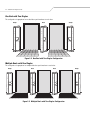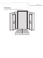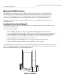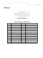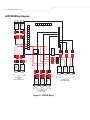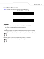
1
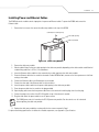
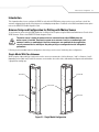
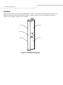
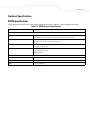
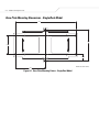
DC600 Portal
Integrator Guide
DC600 Portal Integrator Guide
72E-71772-02
Revision A
August 2005
© 2005 by Symbol Technologies, Inc. All rights reserved.
No part of this publication may be reproduced or used in any form, or by any electrical or mechanical means, without permission in writing from
Symbol. This includes electronic or mechanical means, such as photocopying, recording, or information storage and retrieval systems. The material
in this manual is subject to change without notice.
The software is provided strictly on an “as is” basis. All software, including firmware, furnished to the user is on a licensed basis. Symbol grants
to the user a non-transferable and non-exclusive license to use each software or firmware program delivered hereunder (licensed program). Except
as noted below, such license may not be assigned, sublicensed, or otherwise transferred by the user without prior written consent of Symbol. No
right to copy a licensed program in whole or in part is granted, except as permitted under copyright law. The user shall not modify, merge, or
incorporate any form or portion of a licensed program with other program material, create a derivative work from a licensed program, or use a
licensed program in a network without written permission from Symbol. The user agrees to maintain Symbol’s copyright notice on the licensed
programs delivered hereunder, and to include the same on any authorized copies it makes, in whole or in part. The user agrees not to decompile,
disassemble, decode, or reverse engineer any licensed program delivered to the user or any portion thereof.
Symbol reserves the right to make changes to any software or product to improve reliability, function, or design.
Symbol does not assume any product liability arising out of, or in connection with, the application or use of any product, circuit, or application
described herein.
No license is granted, either expressly or by implication, estoppel, or otherwise under any Symbol Technologies, Inc., intellectual property rights.
An implied license only exists for equipment, circuits, and subsystems contained in Symbol products.
Symbol, Spectrum One, and Spectrum24 are registered trademarks of Symbol Technologies, Inc. Bluetooth is a registered trademark of Bluetooth
SIG. Microsoft, Windows and ActiveSync are either registered trademarks or trademarks of Microsoft Corporation. Other product names mentioned
in this manual may be trademarks or registered trademarks of their respective companies and are hereby acknowledged.
Symbol Technologies, Inc.
One Symbol Plaza
Holtsville, New York 11742-1300
http://www.symbol.com
Patents
This product is covered by one or more of the patents listed on the web site: www.symbol.com/patents
Revision History
Changes to the original manual are listed below:
Change
Date
Description
-01 Rev A
June. 2005
Initial Release
-02 Rev A
August 2005
Chapter 1 Added:
Facility Power Requirements.
Chapter 2 Installation procedures, sequence was updated.
Contents
Revision History . . . . . . . . . . . . . . . . . . . . . . . . . . . . . . . . . . . . . . . . . . . . . . . . . . . . . . . . . . . . . . . . . . . . . . . . . . . iii
About This Guide
Introduction . . . . . . . . . . . . . . . . . . . . . . . . . . . . . . . . . . . . . . . . . . . . . . . . . . . . . . . . . . . . . . . . . . . . . . . . . . . . . ix
Chapter Descriptions . . . . . . . . . . . . . . . . . . . . . . . . . . . . . . . . . . . . . . . . . . . . . . . . . . . . . . . . . . . . . . . . . . . . . . . ix
Notational Conventions . . . . . . . . . . . . . . . . . . . . . . . . . . . . . . . . . . . . . . . . . . . . . . . . . . . . . . . . . . . . . . . . . . . . . ix
Related Documents and Software . . . . . . . . . . . . . . . . . . . . . . . . . . . . . . . . . . . . . . . . . . . . . . . . . . . . . . . . . . . . . ix
Service Information . . . . . . . . . . . . . . . . . . . . . . . . . . . . . . . . . . . . . . . . . . . . . . . . . . . . . . . . . . . . . . . . . . . . . . . . x
Symbol Support Center . . . . . . . . . . . . . . . . . . . . . . . . . . . . . . . . . . . . . . . . . . . . . . . . . . . . . . . . . . . . . . . . . x
Chapter 1. Getting Started
Introduction . . . . . . . . . . . . . . . . . . . . . . . . . . . . . . . . . . . . . . . . . . . . . . . . . . . . . . . . . . . . . . . . . . . . . . . . . . . . 1-3
Facility Power Requirements . . . . . . . . . . . . . . . . . . . . . . . . . . . . . . . . . . . . . . . . . . . . . . . . . . . . . . . . . . . . . . . . 1-3
DC600 LEDs . . . . . . . . . . . . . . . . . . . . . . . . . . . . . . . . . . . . . . . . . . . . . . . . . . . . . . . . . . . . . . . . . . . . . . . . . . . . . 1-4
DC600 Standard Edition . . . . . . . . . . . . . . . . . . . . . . . . . . . . . . . . . . . . . . . . . . . . . . . . . . . . . . . . . . . . . . . . . . . . 1-4
DC600 Professional Edition . . . . . . . . . . . . . . . . . . . . . . . . . . . . . . . . . . . . . . . . . . . . . . . . . . . . . . . . . . . . . . . . . 1-4
Motion Sensor . . . . . . . . . . . . . . . . . . . . . . . . . . . . . . . . . . . . . . . . . . . . . . . . . . . . . . . . . . . . . . . . . . . . . . . 1-4
DC600 Configurations . . . . . . . . . . . . . . . . . . . . . . . . . . . . . . . . . . . . . . . . . . . . . . . . . . . . . . . . . . . . . . . . . . . . . 1-4
vi DC600 Portal Integrator Guide
Chapter 2. Installation
Introduction. . . . . . . . . . . . . . . . . . . . . . . . . . . . . . . . . . . . . . . . . . . . . . . . . . . . . . . . . . . . . . . . . . . . . . . . . . . . . 2-3
Installation Configurations . . . . . . . . . . . . . . . . . . . . . . . . . . . . . . . . . . . . . . . . . . . . . . . . . . . . . . . . . . . . . . . . . .2-3
Two Single DC600s . . . . . . . . . . . . . . . . . . . . . . . . . . . . . . . . . . . . . . . . . . . . . . . . . . . . . . . . . . . . . . . . . . .2-3
One Dual with Two Singles . . . . . . . . . . . . . . . . . . . . . . . . . . . . . . . . . . . . . . . . . . . . . . . . . . . . . . . . . . . . .2-4
Multiple Duals with Two Singles. . . . . . . . . . . . . . . . . . . . . . . . . . . . . . . . . . . . . . . . . . . . . . . . . . . . . . . . .2-4
Two Slim Singles . . . . . . . . . . . . . . . . . . . . . . . . . . . . . . . . . . . . . . . . . . . . . . . . . . . . . . . . . . . . . . . . . . . . .2-5
Mounting the DC600 to the Floor . . . . . . . . . . . . . . . . . . . . . . . . . . . . . . . . . . . . . . . . . . . . . . . . . . . . . . . . . . . . .2-6
Installing the Floor Guard (Optional). . . . . . . . . . . . . . . . . . . . . . . . . . . . . . . . . . . . . . . . . . . . . . . . . . . . . . . . . . .2-6
Installing Power and Ethernet Cables . . . . . . . . . . . . . . . . . . . . . . . . . . . . . . . . . . . . . . . . . . . . . . . . . . . . . . . . .2-7
Powering the XR400 . . . . . . . . . . . . . . . . . . . . . . . . . . . . . . . . . . . . . . . . . . . . . . . . . . . . . . . . . . . . . . . . . . .2-8
Chapter 3. Motion Sensor Configuration
Introduction. . . . . . . . . . . . . . . . . . . . . . . . . . . . . . . . . . . . . . . . . . . . . . . . . . . . . . . . . . . . . . . . . . . . . . . . . . . . . 3-3
Antenna Setup and Configuration for Polling with Motion Sensor . . . . . . . . . . . . . . . . . . . . . . . . . . . . . . . . . . .3-3
Single Model With Two Antennas. . . . . . . . . . . . . . . . . . . . . . . . . . . . . . . . . . . . . . . . . . . . . . . . . . . . . . . .3-3
Dual Model . . . . . . . . . . . . . . . . . . . . . . . . . . . . . . . . . . . . . . . . . . . . . . . . . . . . . . . . . . . . . . . . . . . . . . . . . .3-4
Appendix A. Specifications
Technical Specifications. . . . . . . . . . . . . . . . . . . . . . . . . . . . . . . . . . . . . . . . . . . . . . . . . . . . . . . . . . . . . . . . . . . A-3
DC600 Specifications . . . . . . . . . . . . . . . . . . . . . . . . . . . . . . . . . . . . . . . . . . . . . . . . . . . . . . . . . . . . . . . . . A-3
Base Plate Mounting Dimensions - Single/Dual Model . . . . . . . . . . . . . . . . . . . . . . . . . . . . . . . . . . . . . . A-4
Base Plate and Floor Guard Mounting Dimensions - Single/Dual Model . . . . . . . . . . . . . . . . . . . . . . . . . A-5
Base Plate Mounting Dimensions - Slim Single Model. . . . . . . . . . . . . . . . . . . . . . . . . . . . . . . . . . . . . . . A-5
Base Plate and Floor Guard Mounting Dimensions - Slim Single Model . . . . . . . . . . . . . . . . . . . . . . . . . A-6
Sensor and Light PCB Signals and Pinouts. . . . . . . . . . . . . . . . . . . . . . . . . . . . . . . . . . . . . . . . . . . . . . . . . . . . . A-7
GPIO Signals . . . . . . . . . . . . . . . . . . . . . . . . . . . . . . . . . . . . . . . . . . . . . . . . . . . . . . . . . . . . . . . . . . . . . . . . A-9
LED PCB Wiring Diagram . . . . . . . . . . . . . . . . . . . . . . . . . . . . . . . . . . . . . . . . . . . . . . . . . . . . . . . . . . . . . A-10
Appendix B. XML Software Commands
Reader Status LED Commands . . . . . . . . . . . . . . . . . . . . . . . . . . . . . . . . . . . . . . . . . . . . . . . . . . . . . . . . . . . . . . B-3
Example 1 . . . . . . . . . . . . . . . . . . . . . . . . . . . . . . . . . . . . . . . . . . . . . . . . . . . . . . . . . . . . . . . . . . . . . . . . . . B-3
Example 2 . . . . . . . . . . . . . . . . . . . . . . . . . . . . . . . . . . . . . . . . . . . . . . . . . . . . . . . . . . . . . . . . . . . . . . . . . . B-3
Index
Tell Us What You Think...
About This Guide
Introduction . . . . . . . . . . . . . . . . . . . . . . . . . . . . . . . . . . . . . . . . . . . . . . . . . . . . . . . . . . . . . . . . . . . . . . . . . . . . . ix
Chapter Descriptions . . . . . . . . . . . . . . . . . . . . . . . . . . . . . . . . . . . . . . . . . . . . . . . . . . . . . . . . . . . . . . . . . . . . . . . ix
Notational Conventions . . . . . . . . . . . . . . . . . . . . . . . . . . . . . . . . . . . . . . . . . . . . . . . . . . . . . . . . . . . . . . . . . . . . . ix
Related Documents and Software . . . . . . . . . . . . . . . . . . . . . . . . . . . . . . . . . . . . . . . . . . . . . . . . . . . . . . . . . . . . . ix
Service Information . . . . . . . . . . . . . . . . . . . . . . . . . . . . . . . . . . . . . . . . . . . . . . . . . . . . . . . . . . . . . . . . . . . . . . . . x
Symbol Support Center . . . . . . . . . . . . . . . . . . . . . . . . . . . . . . . . . . . . . . . . . . . . . . . . . . . . . . . . . . . . . . . . . x
viii DC600 Portal Integrator Guide
ix
Introduction
This Integrator Guide provides information about installing and using the DC600 portal system, a fully assembled turn-key solution
that uses Radio Frequency Identification (RFID) for asset identification and tracking goods movement.
Chapter Descriptions
Topics covered in this guide are as follows:
•
•
•
•
•
Chapter 1, Getting Started provides an overview of the DC600 portal system.
Chapter 2, Installation describes how to install the DC600 hardware and components.
Chapter 3, Motion Sensor Configuration describes how to configure the XR400 to work with the DC600 when using a motion
sensor, and how to install the antennas and group them logically using firmware to avoid deployment problems.
Appendix A, Specifications provides technical specifications for the DC600 and motion sensor, signals, and pinouts.
Appendix B, XML Software Commands lists the XML commands for controlling LEDs.
Notational Conventions
The following conventions are used in this document:
•
•
•
•
Italics are used to highlight the following:
• chapters and sections in this and related documents
• dialog box, window and screen names
• drop-down list and list box names
• check box and radio button names
• icons on a screen.
Bold text is used to highlight the following:
• key names on a keypad
• button names on a screen.
Bullets (•) indicate:
• action items
• lists of alternatives
• lists of required steps that are not necessarily sequential.
Sequential lists (e.g., those that describe step-by-step procedures) appear as numbered lists.
Related Documents and Software
The following documents provide more information about the DC600 Portal system.
• DC600 Portal Quick Reference Guide, p/n 72-71771-xx
• XR400 RFID Reader Integrator Guide, p/n 72E-71773-xx
• XR400 Interface Control Guide, p/n 72E-71803-xx
• XR400 Reader C API Programmer Reference Guide, p/n 72E-73028-xx
• TagVis User Guide, p/n 72E-71804-xx
• ReaderComm5DLL Developer Guide, p/n 72E-71805-xx
• DC600 Floor Guard QRG, P/N 72-75043-xx.
For the latest version of this guide and all guides, go to: http://www.symbol.com/manuals.
x DC600 Portal Integrator Guide
Service Information
If an equipment problem occurs, contact the appropriate regional Symbol Support Center . Before calling, locate the product model
number and serial number. Call the Support Center from a phone near the equipment so that the service person can try to talk through
the problem.
If the problem cannot be solved over the phone, the equipment may need to be returned for servicing. If that is necessary, specific
directions will be provided.
Symbol Technologies is not responsible for any damages incurred during shipment if the approved shipping
container is not used. Shipping the units improperly can possibly void the warranty.
If the Symbol product was purchased from a Symbol Business Partner, contact that Business Partner for service
Symbol Support Center
For service information, warranty information or technical assistance contact or call the Symbol Support Center listed below. For the
latest service information go to http://www.symbol.com.
United States 1
Symbol Technologies, Inc.
One Symbol Plaza
Holtsville, New York 11742-1300
1-800-653-5350
Canada
Symbol Technologies Canada, Inc.
5180 Orbitor Drive
Mississauga, Ontario L4W 5L9
905-629-7226
United Kingdom
Symbol Technologies
Symbol Place
Winnersh Triangle, Berkshire RG41 5TP
United Kingdom
0800 328 2424 (Inside UK)
+44 118 945 7529 (Outside UK)
Asia/Pacific
Symbol Technologies Asia, Inc.
230 Victoria Street #04-05
Bugis Junction Office Tower
Singapore 188024
337-6588 (Inside Singapore)
+65-337-6588 (Outside Singapore)
Australia
Symbol Technologies Pty. Ltd.
432 St. Kilda Road
Melbourne, Victoria 3004
1-800-672-906 (Inside Australia)
+61-3-9866-6044 (Outside Australia)
Austria/Österreich
Symbol Technologies Austria GmbH
Prinz-Eugen Strasse 70 / 2.Haus
1040 Vienna, Austria
01-5055794-0 (Inside Austria)
+43-1-5055794-0 (Outside Austria)
Denmark/Danmark
Symbol Technologies AS
Dr. Neergaardsvej 3
2970 Hørsholm
7020-1718 (Inside Denmark)
+45-7020-1718 (Outside Denmark)
Europe/Mid-East Distributor Operations
Contact your local distributor or call
+44 118 945 7360
xi
Finland/Suomi
Oy Symbol Technologies
Kaupintie 8 A 6
FIN-00440 Helsinki, Finland
9 5407 580 (Inside Finland)
+358 9 5407 580 (Outside Finland)
France
Symbol Technologies France
Centre d'Affaire d'Antony
3 Rue de la Renaissance
92184 Antony Cedex, France
01-40-96-52-21 (Inside France)
+33-1-40-96-52-50 (Outside France)
Germany/Deutschland
Symbol Technologies GmbH
Waldstrasse 66
D-63128 Dietzenbach, Germany
6074-49020 (Inside Germany)
+49-6074-49020 (Outside Germany)
Italy/Italia
Symbol Technologies Italia S.R.L.
Via Cristoforo Columbo, 49
20090 Trezzano S/N Navigilo
Milano, Italy
2-484441 (Inside Italy)
+39-02-484441 (Outside Italy)
Latin America Sales Support
7900 Glades Road
Suite 340
Boca Raton, Florida 33434 USA
1-800-347-0178 (Inside United States)
+1-561-483-1275 (Outside United States)
Mexico/México
Symbol Technologies Mexico Ltd.
Boulevard Manuel Ávila Camacho # 24- 9 Piso
Col. Lomas de Chapultepec
México DF: CP 11000
Mexico City, DF, Mexico
5-520-1835 (Inside Mexico)
+52-5-520-1835 (Outside Mexico)
Netherlands/Nederland
Symbol Technologies
Kerkplein 2, 7051 CX
Postbus 24 7050 AA
Varsseveld, Netherlands
315-271700 (Inside Netherlands)
+31-315-271700 (Outside Netherlands)
Norway/Norge
Symbol’s registered and mailing address:
Symbol Technologies Norway
Helsfyr Panorama
Innspurten 9
Oslo N-0663
Symbol’s repair depot and shipping address:
Symbol Technologies Norway
Enebakkveien 123
N-0680 OSLO, Norway
+47 2232 4375
South Africa
Symbol Technologies Africa Inc.
Block B2
Rutherford Estate
1 Scott Street
Waverly 2090 Johannesburg
Republic of South Africa
11-809 5311 (Inside South Africa)
+27-11-809 5311 (Outside South Africa)
Spain/España
Symbol Technologies S.L.
Avenida de Bruselas, 22
Edificio Sauce
Alcobendas, Madrid 28108
Spain
+913244000 (Inside Spain)
+34-9-1-320-39-09 (Outside Spain)
xii DC600 Portal Integrator Guide
Sweden/Sverige
“Letter” address:
Symbol Technologies AB
Box 1354
S-171 26 SOLNA
Sweden
Visit/shipping address:
Symbol Technologies AB
Solna Strandväg 78
S-171 54 SOLNA
Sweden
Switchboard: 08 445 29 00 (domestic)
Call Center: +46 8 445 29 29 (international)
Support E-Mail: Sweden.Support@se.symbol.com
1Customer support is available 24 hours a day, 7 days a week.
If you purchased your Symbol product from a Symbol Business Partner, contact that Business Partner for service.
Getting Started
Introduction . . . . . . . . . . . . . . . . . . . . . . . . . . . . . . . . . . . . . . . . . . . . . . . . . . . . . . . . . . . . . . . . . . . . . . . . . . . . 1-3
Facility Power Requirements . . . . . . . . . . . . . . . . . . . . . . . . . . . . . . . . . . . . . . . . . . . . . . . . . . . . . . . . . . . . . . . . 1-3
DC600 LEDs . . . . . . . . . . . . . . . . . . . . . . . . . . . . . . . . . . . . . . . . . . . . . . . . . . . . . . . . . . . . . . . . . . . . . . . . . . . . . 1-4
DC600 Standard Edition . . . . . . . . . . . . . . . . . . . . . . . . . . . . . . . . . . . . . . . . . . . . . . . . . . . . . . . . . . . . . . . . . . . . 1-4
DC600 Professional Edition . . . . . . . . . . . . . . . . . . . . . . . . . . . . . . . . . . . . . . . . . . . . . . . . . . . . . . . . . . . . . . . . . 1-4
Motion Sensor . . . . . . . . . . . . . . . . . . . . . . . . . . . . . . . . . . . . . . . . . . . . . . . . . . . . . . . . . . . . . . . . . . . . . . . 1-4
DC600 Configurations . . . . . . . . . . . . . . . . . . . . . . . . . . . . . . . . . . . . . . . . . . . . . . . . . . . . . . . . . . . . . . . . . . . . . 1-4
1-2
DC600 Portal Integrator Guide
Getting Started 1-3
Introduction
The DC600 portal system is a fully assembled turn-key solution that uses Radio Frequency Identification (RFID) for asset identification
and tracking goods movement in manufacturing plants, cargo logistics, distribution centers, warehouses, and stores.
The DC600 includes an integrated RFID reader and high-performance antennas for fast, accurate reading of RFID tags. All internal
antenna-to-reader connections are included to reduce procurement time and installation effort. The DC600 can leverage two or more
antennas for each dock door to increase coverage.
The DC600 can sustain minor non-direct pallet impact. Its bolted installation makes it robust for industrial environments. The DC600
is dust and water resistance to ensure reliable service in harsh environments and can work in temperatures between -4o F to
+122o F (-20o C to 50o C) and humidity of 5% to 95% RH.
Cable Entry Module
Electronics Module
Portal Status
Indicator Lights
Reader Status Indicator Lights
Motion Sensor
Antennas
RFID Reader
Antennas
Figure 1-1. DC600 Parts
Facility Power Requirements
The DC600 portal system requires the following power input requirements:
1.
2.
3.
4.
A dedicated AC circuit is recommended (but not required), 4.5 amps is the maximum current.
AC voltage must be within the 90VAC - 264VAC range.
AC power cycle requirements must be within 47Hz to 63Hz.
An external power switch that disconnects all poles is recommended. The power switch for the DC600 is located inside of
the Cable Entry Module.
1-4
DC600 Portal Integrator Guide
DC600 LEDs
The DC600 includes two sets of LEDs described in Table 1-1.
Table 1-1. DC600 LED Indications
LED
Indication
Portal Status LEDs (located on side of DC600, near the top, non-programmable)
Green
DC600 is powered on.
Red
Hardware fault.
Reader Status LEDs (located on front/rear of DC600, near the top, programmable)
Red/Green/Amber
All three LEDs light upon power-up.
Amber
Successful tag read.
Green
Reader firmware driven or programmable via XML commands.
Red
Off by default, but programmable via XML commands.
DC600 Standard Edition
The Standard Edition DC600s include the following components:
•
•
•
•
DC600 Dock Door Frame: The dock door frame provides a bolted installation and houses the XR400 reader and high
performance antennas.
XR400 RFID Reader: Refer to the XR400 Integrator Guide.
High Performance Antennas: The antennas connect to the reader to enable tag reading in the read range. Dual models
include four antennas, and single (left or right) models include two antennas.
Portal and reader status LEDs.
DC600 Professional Edition
The Professional Edition DC600s include all of the components offered in the Standard Edition, as well as the motion
sensor.
Motion Sensor
The motion sensor initiates tag reads when movement is it detected. This ensures antennas only read tags when tag
movement occurs through the dock door, e.g., when pallets pass through the DC600 system.
DC600 Configurations
The DC600 is available in single (left or right) and dual configurations for monitoring different types of dock doors.
Businesses can choose between the Standard or Professional editions depending on requirements.
The DC600 offers three configurations:
•
•
•
Single: Includes two high-performance antennas mounted on a single frame that installs on the side of a dock door. This is
usually mounted as a paired system with another single or another dual.
Dual: Includes four high-performance antennas mounted on a single frame that installs between two dock doors. This is
usually mounted as a paired system with one or two singles.
Slim Single: Includes two high-performance antennas mounted on a single compact frame that installs against a wall. This
is usually mounted as a paired system with another single model or a single and dual model.
See Figure 1-1 on page 1-3 for DC600 model illustrations.
Installation
Introduction . . . . . . . . . . . . . . . . . . . . . . . . . . . . . . . . . . . . . . . . . . . . . . . . . . . . . . . . . . . . . . . . . . . . . . . . . . . . 2-3
Installation Configurations. . . . . . . . . . . . . . . . . . . . . . . . . . . . . . . . . . . . . . . . . . . . . . . . . . . . . . . . . . . . . . . . . . 2-3
Two Single DC600s . . . . . . . . . . . . . . . . . . . . . . . . . . . . . . . . . . . . . . . . . . . . . . . . . . . . . . . . . . . . . . . . . . . 2-3
One Dual with Two Singles . . . . . . . . . . . . . . . . . . . . . . . . . . . . . . . . . . . . . . . . . . . . . . . . . . . . . . . . . . . . . 2-4
Multiple Duals with Two Singles . . . . . . . . . . . . . . . . . . . . . . . . . . . . . . . . . . . . . . . . . . . . . . . . . . . . . . . . 2-4
Two Slim Singles . . . . . . . . . . . . . . . . . . . . . . . . . . . . . . . . . . . . . . . . . . . . . . . . . . . . . . . . . . . . . . . . . . . . . 2-5
Mounting the DC600 to the Floor. . . . . . . . . . . . . . . . . . . . . . . . . . . . . . . . . . . . . . . . . . . . . . . . . . . . . . . . . . . . . 2-6
Installing the Floor Guard (Optional) . . . . . . . . . . . . . . . . . . . . . . . . . . . . . . . . . . . . . . . . . . . . . . . . . . . . . . . . . . 2-6
Installing Power and Ethernet Cables . . . . . . . . . . . . . . . . . . . . . . . . . . . . . . . . . . . . . . . . . . . . . . . . . . . . . . . . . 2-7
Powering the XR400. . . . . . . . . . . . . . . . . . . . . . . . . . . . . . . . . . . . . . . . . . . . . . . . . . . . . . . . . . . . . . . . . . . 2-8
2-2
DC600 Portal Integrator Guide
Installation 2-3
Introduction
This chapter describes how to install the DC600 and accessories. Before beginning the installation refer to the Facility
Power Requirements on page 1-3 and confirm that the DC600 power requirements have been satisfied. The chapter is
divided into 3 sections:
•
Installation Configurations
Provides an overview of some of the DC600 installation configurations.
•
Mounting the DC600
Provides mounting instructions.
•
Connecting Power and Communications
Provides power and communications installation and connection instructions.
Installation Configurations
Install the DC600 in the configuration that best suits requirements and maximizes performance.
Two Single DC600s
This configuration is appropriate for a single dock door, consider two single models.
Figure 2-1. Two Singles Configuration
2-4
DC600 Portal Integrator Guide
One Dual with Two Singles
This configuration is appropriate for two dock doors positioned next to each other.
Single
Dual
Single
Figure 2-2. One Dual with Two Singles Configuration
Multiple Duals with Two Singles
This configuration is appropriate for multiple dock doors positioned next to each other.
Single
Dual
Dual
Figure 2-3. Multiple Duals with Two Singles Configuration
Single
Installation 2-5
Two Slim Singles
This configuration is appropriate for internal doors with limited space.
Figure 2-4. Two Slim Singles Configuration
2-6
DC600 Portal Integrator Guide
Mounting the DC600 to the Floor
The DC600 includes a base plate with six holes for bolting the DC600 to the floor (four holes for the Slim Single model).
After selecting a location for the DC600, drill bolt holes into the floor that align with the holes in the base plate. Insert six
(or four for the Slim Single model) 0.5 in. (1.27 cm) diameter ground fastening bolts through the base plate and into the
bolt holes to secure the DC600 to the floor. See Base Plate Mounting Dimensions - Single/Dual Model on page A-4.
For the Slim Single model, in addition to securing the DC600 to the floor, also use the appropriate wall fasteners to secure
the DC600 to the wall.
Installing the Floor Guard (Optional)
The DC600 Floor Guard QRG, P/N 72-75043-xx provides printed a full size mounting template (in the box to provide for accurate
positioning of the DC600 Floor Guard.
To install the optional floor guard:
1. Refer to Installation Configurations on page 2-3 for information on DC600 configuration and location options.
2. Position the DC600 Mounting Template under the DC600 and line up the DC600 mounting holes with the mounting holes on
the mounting template. The mounting template shows the position of the Floor Guard two right hand mounting holes.
3. Use the mounting template to locate the DC600 Floor Guard directly over the mounting template locating holes.
4. Use the Floor Guard to mark the mounting hole locations on the floor
5. Remove the DC600 Floor Guard and prepare the floor for mounting as applicable for the floor material.
6. Replace the DC600 Floor Guard and attach with fasteners appropriate for the floor material.
To install the floor guard, drill four bolt holes into the concrete floor that align with the four tabs in the floor guard. Insert four standard
0.5 in. (1.27 cm) diameter fastening bolts through the floor guard tabs and into the bolt holes to secure to the floor. See Base Plate
and Floor Guard Mounting Dimensions - Single/Dual Model on page A-5.
Figure 2-5. Floor Guard
Installation 2-7
Installing Power and Ethernet Cables
The DC600 electronics module contains input points for power and Ethernet cables. To power the DC600 and connect the
Ethernet cable:
1. Remove the four screws that secure the cable entry module to the top of the DC600.
Communications Cable Opening
Power Cable Opening
Cable Entry Module
Figure 2-6. Cable Entry Module
2. Remove the cable entry module.
3. Obtain conduit fittings for the two cable openings in the cable entry module, depending on the cable conduits used. Nominal
conduit fitting trade size is 0.75 in (1.9 cm) diameter.
4. Insert the Ethernet cable conduit into the communications cable opening in the cable entry module.
5. Route the Ethernet cable from its conduit to the reader. For dual DC600 models, remove one of the top antennas to facilitate
routing to the reader.
6. Connect the Ethernet cable to the Ethernet port on the reader.
7. Connect the other end of the Ethernet cable to the host device.
8. Insert the power cable conduit into the power cable opening in the cable entry module.
9. Route the power cable from its conduit to the plug provided.
10. Open the plug and connect the three power cable wires to the terminals inside the plug, then close the plug.
11. Connect the plug to the socket of the IEC 320 module on top of the electronics module.
12. Plug the other end of the power cable into an AC power source.
The DC600 power switch is located on the IEC 320 power entry module. Turn the switch on or off as desired
before replacing the cable entry module.
13. Replace the cable entry module by securing with the four screws removed in Step 1.
For pinout and wiring specifications for electronics module components, see Appendix A, Specifications.
2-8
DC600 Portal Integrator Guide
Powering the XR400
If replacing the XR400 Reader within the DC600 for any reason, shut off power to the DC600 system before disconnecting power from
the reader.
Note
Applying power to the XR400 reader before establishing proper grounding can cause a benign spark.
Adhere to the following procedures to ensure proper grounding.
To power the reader:
1. Insert the power supply's barrel connector into the XR400's power port.
2. Turn on the power switch on the DC600 Electronics Module. The green Power LED on the XR400 lights to indicate the XR400
is powered on.
To power down the reader:
1. Turn off the power switch on the DC600 Electronics Module. The green Power LED turns off to indicate that the device is
powered off and the system is not operational.
2. Remove the barrel connector from the XR400's power port.
Do not power off the XR400 until the yellow LED is off, indicating that reads are not in process.
Note
Motion Sensor Configuration
Introduction . . . . . . . . . . . . . . . . . . . . . . . . . . . . . . . . . . . . . . . . . . . . . . . . . . . . . . . . . . . . . . . . . . . . . . . . . . . . 3-3
Antenna Setup and Configuration for Polling with Motion Sensor. . . . . . . . . . . . . . . . . . . . . . . . . . . . . . . . . . .3-3
Single Model With Two Antennas . . . . . . . . . . . . . . . . . . . . . . . . . . . . . . . . . . . . . . . . . . . . . . . . . . . . . . . 3-3
Dual Model. . . . . . . . . . . . . . . . . . . . . . . . . . . . . . . . . . . . . . . . . . . . . . . . . . . . . . . . . . . . . . . . . . . . . . . . . . 3-4
3-2
DC600 Portal Integrator Guide
Motion Sensor Configuration 3-3
Introduction
This chapter describes how to configure the XR400 to work with the DC600 when using a motion sensor, and how to install the
antennas and group them logically using firmware to avoid deployment problems. For details on the Web-based administrator option
refer to the XR400 RFID Reader Integrator Guide.
Antenna Setup and Configuration for Polling with Motion Sensor
To use the motion sensor with the DC600 enable the Use Motion Detector option using the Web-based Administrator Console of the
XR400 firmware. Refer to the XR400 RFID Reader Integrator Guide.
The motion sensor is tied to the antennas that are connected to the side of DC600 where the
motion sensor is installed. Therefore the system treats antennas 1 and 2 as a combined pair, and
antennas 3 and 4 as a combined pair. Once the antenna ports are combined, the host application
WARNING can only command the 1st and 3rd port. Any other pairing or reconfiguration results in degraded
performance.
Following are recommended antenna configurations when using a motion sensor. Avoid using other configurations.
Single Model With Two Antennas
When using the single model (left / right) with a motion sensor use antenna pairs of either Antennas 1 and 2 or Antennas 3 and 4
(depending on the model used). Ensure the antennas are mounted on the correct side as indicated by the diagram and combined into
a group before reading tags.
Antenna #4
Antenna #2
Side of Rack
Antenna #3
Antenna #1
Figure 3-1. Single Model Configuration
3-4
DC600 Portal Integrator Guide
Dual Model
When using a dual model with motion sensors and deploying all 4 antennas, ensure antennas 1 and 2 are stacked on the front of the
DC600 (the reader faces the front) and combined, and antennas 3 and 4 are stacked on the rear of the DC600 and combined (i.e.,
Antennas 1 and 2 are group 1, Antennas 3 and 4 are group 2).
Antenna #4
Antenna #2
Side of Rack
Antenna #3
Antenna #1
Figure 3-2. Dual Model Configuration
Specifications
Technical Specifications . . . . . . . . . . . . . . . . . . . . . . . . . . . . . . . . . . . . . . . . . . . . . . . . . . . . . . . . . . . . . . . . . . A-3
DC600 Specifications . . . . . . . . . . . . . . . . . . . . . . . . . . . . . . . . . . . . . . . . . . . . . . . . . . . . . . . . . . . . . . . . . A-3
Base Plate Mounting Dimensions - Single/Dual Model . . . . . . . . . . . . . . . . . . . . . . . . . . . . . . . . . . . . . . A-4
Base Plate and Floor Guard Mounting Dimensions - Single/Dual Model . . . . . . . . . . . . . . . . . . . . . . . . . A-5
Base Plate Mounting Dimensions - Slim Single Model . . . . . . . . . . . . . . . . . . . . . . . . . . . . . . . . . . . . . . A-5
Base Plate and Floor Guard Mounting Dimensions - Slim Single Model . . . . . . . . . . . . . . . . . . . . . . . . . A-6
Sensor and Light PCB Signals and Pinouts . . . . . . . . . . . . . . . . . . . . . . . . . . . . . . . . . . . . . . . . . . . . . . . . . . . . A-7
GPIO Signals. . . . . . . . . . . . . . . . . . . . . . . . . . . . . . . . . . . . . . . . . . . . . . . . . . . . . . . . . . . . . . . . . . . . . . . . A-9
LED PCB Wiring Diagram . . . . . . . . . . . . . . . . . . . . . . . . . . . . . . . . . . . . . . . . . . . . . . . . . . . . . . . . . . . . . A-10
A-2 DC600 Portal Integrator Guide
Specifications
Technical Specifications
DC600 Specifications
The following table summarizes the DC600 intended operating environment and general technical hardware specifications.
Table A-1. DC600 Technical Specifications
Feature
Description
Physical Specifications
Dimensions
Single/Dual: 76.78" H x 21.00" W x 7.87" D (195.02 cm H x 53.34 cm W x 19.99 cm D)
Slim Single: 75.88" H x 17.25" W x 4.75" D (192.74 cm H x 43.82 cm W x 12.07 cm D)
Base Plate Dimensions
Single/Dual: 21.00" W x 10.87" D (53.34 cm W x 27.61 cm D)
Slim Single: 17.25" W x 4.75" D (43.82 cm W x 12.07 cm D)
Weight
Single/Dual: ~ 120 lbs (54.5 kg)
Slim Single: ~ 60 lbs (27.2 kg)
Power
Voltage: 100 - 240 VAC
Current: 4.5 Amps (maximum)
Frequency: 50-60 Hz
Environmental Specifications
Operational Temperature
-4° to +131° F (-20° to +55° C)
Storage Temperature
-40° to +185° F (-40° to +85° C)
Humidity
5-95% non-condensing
A-3
A-4 DC600 Portal Integrator Guide
Base Plate Mounting Dimensions - Single/Dual Model
19.69
9.87
5.91
2X 1.98
9.84
Figure A-1. Base Plate Mounting Pattern - Single/Dual Model
Dimensions are in inches.
Specifications
A-5
Base Plate and Floor Guard Mounting Dimensions - Single/Dual Model
2X 2.27
3.90
2.00
4.55
0.57
4.46
2X 7.66
Dimensions are in inches.
8.91
Figure A-2. Base Plate and Floor Guard Mounting Pattern - Single/Dual Model
Base Plate Mounting Dimensions - Slim Single Model
2.75
16.00
Dimensions are in inches.
Figure A-3. Base Plate Mounting Pattern - Slim Single Model
A-6 DC600 Portal Integrator Guide
Base Plate and Floor Guard Mounting Dimensions - Slim Single Model
2X 4.12
0.49
2.26
4.55
2X 7.66
8.91
Dimensions are in inches.
Figure A-4. Base Plate and Floor Guard Mounting Pattern - Slim Single Model
Specifications
Sensor and Light PCB Signals and Pinouts
Figure A-5. PCB Diagram
Table A-2. J4 Pinout: 12-Pin Terminal Block Connector
Pin Number
Pin Name
Direction
Description
1
LEFT_MOTION_SENSOR_PWR
-
24 VDC to power left motion sensor
2
LEFT_MOTION_SENSOR_NO
I
Left motion sensor input signal
3
LEFT_MOTION_SENSOR_COM
-
Left motion sensor common
4
RIGHT_MOTION_SENSOR_NO
I
Right motion sensor input signal
5
RIGHT_MOTION_SENSOR_COM
-
Right motion sensor common
6
RIGHT_MOTION_SENSOR_PWR
-
24 VDC to power right motion sensor
7
SPARE_PWR
-
24 VDC spare power
8
SPARE_COM
O
Spare common
9
SPARE_GND
-
Spare ground
10
CHASSIS_GRN
-
Chassis green LED cathode
11
CHASSIS_COM
-
Chassis red and green LED anode
12
CHASSIS_RED
O
Chassis red LED cathode
A-7
A-8 DC600 Portal Integrator Guide
Table A-3. J5 Pinout: 8-Pin Terminal Block Connector
Pin Number
Pin Name
Direction
Description
1
RIGHT_SENSOR_PWR
-
24 VDC to power right photoelectric sensor
2
RIGHT_ SENSOR
I
Right Photoelectric sensor input signal
3
LEFT _SENSOR_PWR
-
24VDC to power left photoelectric sensor
4
LEFT _SENSOR
I
Left photoelectric sensor input signal
5
RIGHT _SENSOR_COM
-
Right sensor common
6
LEFT _SENSOR_COM
-
Left sensor common
7
SENSOR_GND
-
Sensor ground
8
SENSOR_GND
-
Sensor ground
Table A-4. J6 Pinout: 10-Pin Terminal Block Connector
Pin Number
Pin Name
Direction
Description
1
RIGHT_LIGHT_PWR
-
24 VDC to power right light bar
2
RIGHT_RED
O
Right red light control signal
3
RIGHT_YEL
O
Right yellow light control signal
4
RIGHT_GRN
O
Right green light control signal
5
LEFT_LIGHT_PWR
-
24 VDC to power left light bar
6
LEFT_RED
O
Left red light control signal
7
LEFT_YEL
O
Left yellow light control signal
8
LEFT_GRN
O
Left green light control signal
9
LEFT_LIGHT_COM
-
Left light common
10
RIGHT_LIGHT_COM
-
Right light common
Specifications
GPIO Signals
Figure A-6. GPIO Connector
Table A-5. J3 Pinout: External GPIO Connector
Pin Number
Pin Name
Direction
Description
1
GND
-
Ground
2
AX1_LCLK
I
External GPIO Input - Bit 1
3
AX3
I
External GPIO Input - Bit 3
4
AX5
I
External GPIO Input - Bit 5
5
AI1_RIGHT_SENSOR
O
External GPIO Output - Bit 1
6
AI3
O
External GPIO Output - Bit 3
7
AI5
O
External GPIO Output - Bit 5
8
GND
-
Ground
9
AX0_CLK
I
External GPIO Input - Bit 0
10
AX2_DIN
I
External GPIO Input - Bit 2
11
AX4
I
External GPIO Input - Bit 4
12
AI0_LEFT_SENSOR
O
External GPIO Output - Bit 0
13
AI2
O
External GPIO Output - Bit 2
14
AI4
O
External GPIO Output - Bit 4
15
5.0V_GP
I
5.4 V Power
A-9
A-10 DC600 Portal Integrator Guide
LED PCB Wiring Diagram
Red
Green
8
7
6
5
1
4
3
2
1
J5
2
10
3
9
4
8
5
7
6
7
J4
J6
6
5
8
4
9
3
10
2
11
1
12
Left Side Tag Read
Status LEDs
Figure A-7. LED PCB Wiring
Right Side Tag
Read Status LEDs
Green
Red
Red
Yellow
Green
Pedestal Status
LEDs
(Left and Right Side)
Yellow
Power
In
Red
Green
Data
Conn
XML Software Commands
Reader Status LED Commands. . . . . . . . . . . . . . . . . . . . . . . . . . . . . . . . . . . . . . . . . . . . . . . . . . . . . . . . . . . . . . B-3
Example 1 . . . . . . . . . . . . . . . . . . . . . . . . . . . . . . . . . . . . . . . . . . . . . . . . . . . . . . . . . . . . . . . . . . . . . . . . . . .B-3
Example 2 . . . . . . . . . . . . . . . . . . . . . . . . . . . . . . . . . . . . . . . . . . . . . . . . . . . . . . . . . . . . . . . . . . . . . . . . . . .B-3
B-2 DC600 Portal Integrator Guide
XML Software Commands
Reader Status LED Commands
Table B-1 lists the XML commands for controlling the red and green reader status LEDs.
Table B-1. XML Commands for LEDs
Function
Description
rred
Turns on the right red LED
rrto
Sets the time out of the right red LED
rgreen
Turns on the right green LED
rgto
Sets the time out of the right green LED
lred
Turns on the left red LED
lrto
Sets the time out of the left red LED
lgreen
Turns on the left green LED
lgto
Sets the time out of the left green LED
Example 1
The following command turns off the right red LED for a reader with IP address 192.168.127.254:
http://192.168.127.254/cgi-bin/dataProxy?oper=setLightIndicator&rred=off
Example 2
The following command turns on the right red LED indefinitely and turns on the left green LED for one second:
http://192.168.127.254/cgi-bin/dataProxy?oper=setLightIndicator&rred=on&rrto=0&lgreen=on&lgto=10
The time out parameter is in 100 ms intervals. For example lgto=10 sets the time out to 1000 ms, or 1 second.
Repeat XML commands for each color in the light bar and for each light bar, i.e., left and right.
XML commands only control the red and green LEDs in the light bars.
B-3
B-4 DC600 Portal Integrator Guide
Index
B
E
bullets . . . . . . . . . . . . . . . . . . . . . . . . . . . . . . . . . . . . . ix
ethernet
connection . . . . . . . . . . . . . . . . . . . . . . . . . . . . 2-7
C
cables
ethernet . . . . . . . . . . . . . . . . . . . . . . . . . . . . . .2-7
power . . . . . . . . . . . . . . . . . . . . . . . . . . . . . . . .2-7
commands
reader status LED . . . . . . . . . . . . . . . . . . . . . . .B-3
configurations . . . . . . . . . . . . . . . . . . . . . . . . . . . . . .1-4
dual . . . . . . . . . . . . . . . . . . . . . . . . . . . . . . . . . .1-4
installation . . . . . . . . . . . . . . . . . . . . . . . . . . . .2-3
professional edition . . . . . . . . . . . . . . . . . . . . .1-4
single . . . . . . . . . . . . . . . . . . . . . . . . . . . . 1-4, 3-3
slim single . . . . . . . . . . . . . . . . . . . . . . . . . . . . .1-4
standard edition . . . . . . . . . . . . . . . . . . . . . . . .1-4
connection . . . . . . . . . . . . . . . . . . . . . . . . . . . . . . . . .2-7
ethernet . . . . . . . . . . . . . . . . . . . . . . . . . . . . . .2-7
mounting . . . . . . . . . . . . . . . . . . . . . . . . . . . . . .2-3
power . . . . . . . . . . . . . . . . . . . . . . . . . . . . . . . .2-7
powering XR400 . . . . . . . . . . . . . . . . . . . . . . . .2-8
conventions
notational . . . . . . . . . . . . . . . . . . . . . . . . . . . . . . ix
D
dimensions . . . . . . . . . . . . . . . . . . . . . . . . . . . . . . . . A-3
dual model . . . . . . . . . . . . . . . . . . . . . . . . . . . . . . . . .1-4
G
GPIO signals . . . . . . . . . . . . . . . . . . . . . . . . . . . . . . . A-9
I
information, service . . . . . . . . . . . . . . . . . . . . . . . . . . . x
installation . . . . . . . . . . . . . . . . . . . . . . . . . . . . . . . . 2-7
configurations . . . . . . . . . . . . . . . . . . . . . . . . . 2-3
ethernet . . . . . . . . . . . . . . . . . . . . . . . . . . . . . . 2-7
motion sensor . . . . . . . . . . . . . . . . . . . . . . . . . 3-3
mounting . . . . . . . . . . . . . . . . . . . . . . . . . . . . . 2-3
power . . . . . . . . . . . . . . . . . . . . . . . . . . . . . . . 2-7
powering XR400 . . . . . . . . . . . . . . . . . . . . . . . 2-8
L
LED PCB
wiring . . . . . . . . . . . . . . . . . . . . . . . . . . . . . . A-10
LEDs
indications . . . . . . . . . . . . . . . . . . . . . . . . . . . . 1-4
portal status . . . . . . . . . . . . . . . . . . . . . . . . . . 1-4
reader status . . . . . . . . . . . . . . . . . . . . . . . . . . 1-4
reader status commands . . . . . . . . . . . . . . . . . B-3
M
motion sensor . . . . . . . . . . . . . . . . . . . . . . . . . . . . . . 1-4
configuration . . . . . . . . . . . . . . . . . . . . . . . . . . 3-3
IN-2
DC600 Portal Integrator Guide
mounting . . . . . . . . . . . . . . . . . . . . . . . . . . . . . . . . . .2-3
O
operating environment . . . . . . . . . . . . . . . . . . . . . . . A-3
P
parts diagram . . . . . . . . . . . . . . . . . . . . . . . . . . . . . . .1-3
pinouts . . . . . . . . . . . . . . . . . . . . . . . . . . . . . . . . . . . A-7
terminal block . . . . . . . . . . . . . . . . . . . . . . . . . A-7
power
connecting . . . . . . . . . . . . . . . . . . . . . . . . . . . . .2-7
connecting XR400 . . . . . . . . . . . . . . . . . . . . . . .2-8
specification . . . . . . . . . . . . . . . . . . . . . . . . . . A-3
S
service information . . . . . . . . . . . . . . . . . . . . . . . . . . . x
signals
GPIO . . . . . . . . . . . . . . . . . . . . . . . . . . . . . . . . A-9
single model . . . . . . . . . . . . . . . . . . . . . . . . . . . . . . . .1-4
slim single model . . . . . . . . . . . . . . . . . . . . . . . . . . . .1-4
specifications . . . . . . . . . . . . . . . . . . . . . . . . . . . . . . A-3
symbol support center . . . . . . . . . . . . . . . . . . . . . . . . . x
T
technical specifications . . . . . . . . . . . . . . . . . . . . . . A-3
terminal block pinouts . . . . . . . . . . . . . . . . . . . . . . . A-7
W
weight . . . . . . . . . . . . . . . . . . . . . . . . . . . . . . . . . . . A-3
X
XML commands . . . . . . . . . . . . . . . . . . . . . . . . . . . . B-3
Tell Us What You Think...
We’d like to know what you think about this Manual. Please take a moment to fill out this questionnaire and fax this form
to: (631) 738-3318, or mail to:
Symbol Technologies, Inc.
One Symbol Plaza M/S B-4
Holtsville, NY 11742-1300
Attention: Technical Publications Manager
IMPORTANT: If you need product support, please call the appropriate customer support number provided. Unfortunately,
we cannot provide customer support at the fax number above.
Manual Title:___________________________________________
(please include revision level)
How familiar were you with this product before using this manual?
Very familiar
Slightly familiar
Not at all familiar
Did this manual meet your needs? If not, please explain.
______________________________________________________________________________________
______________________________________________________________________________________
______________________________________________________________________________________
______________________________________________________________________________________
What topics need to be added to the index, if applicable?
______________________________________________________________________________________
______________________________________________________________________________________
______________________________________________________________________________________
______________________________________________________________________________________
What topics do you feel need to be better discussed? Please be specific.
______________________________________________________________________________________
______________________________________________________________________________________
______________________________________________________________________________________
______________________________________________________________________________________
What can we do to further improve our manuals?
______________________________________________________________________________________
______________________________________________________________________________________
______________________________________________________________________________________
______________________________________________________________________________________
Thank you for your input—We value your comments.
Symbol Technologies, Inc.
One Symbol Plaza
Holtsville, New York 11742-1300
http://www.symbol.com
72E-71772-02
Revision A - August 2005