1
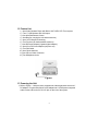
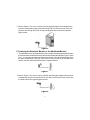
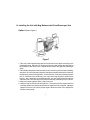
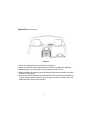
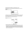
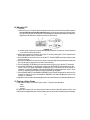
VBP3000
VIDEO IN A BAG SYSTEM WITH DETACHABLE 5" LCD
TV/MONITOR AND VIDEO CASSETTE PLAYER
A. Introduction
Thank you for selecting this “Video in a Bag” System. The system's main features include
two 5" Liquid Crystal Display (LCD) TV/Monitors and Video Cassette Player (VCP) (see
page 4 for a detailed feature list). The system utilizes the latest state of the art electronics
and is designed for use in vehicles, hotels, offices or your home. The “Video in a Bag”
System is constructed to provide years of reliable, trouble-free service. The system is
compact so that you can take it with you anywhere and is designed for quick and easy
installation. The system comes with two detachable displays that can be utilized and
stored separately from the main unit. An additional monitor can be purchased and added
to the system setup allowing you to utilize three monitors at once (two external and one
attached). The connection of the additional is plug & play.
Please read the entire instruction manual supplied with this product prior to operation.
The documentation will assist you in installing the system properly to obtain the best
equipment performance. All manuals should be stored for later use.
B. Precautions
1. The “Video in a Bag” System MUST be powered from switched “Accessory” power
(i.e. not directly from the car battery). Power should be applied to the unit when the
ignition key is in the Run and/or Accessory positions.
NOTE: To prevent battery discharge, disconnect the “Video in a Bag” System jack from
the cigarette lighter socket when the unit is not in use.
2. IMPORTANT!: There are two short Velcro straps located inside the bag. These
straps are used to anchor the system securely inside the bag using the loop
brackets on either side of the system. This will prevent the system from falling out
and being damaged in transport or while in use in your vehicle.
3. Ensure that the LCD TV/Monitor, VCP and the Bag are installed in accordance
with the instructions and illustrations provided in this manual.
4. The “S” hooks and all straps must be fastened correctly to secure the system in the
vehicle in the event of an accident.
5. Operate the “Video in a Bag” System with the Bag open to ensure proper ventilation
of the monitor and the VCP.
6. The system intended to be mounted for rear seat viewing only. DO NOT USE THE
SYSTEM IN THE FRONT SEAT WHILE OPERATING YOUR VEHICLE.
2
INST
ALL
AT ION INSTRUC
INSTALL
ALLA
INSTRUCTT IONS
C. Cautions and Warnings
1. Cleaning Video Head
To prevent video head clogging, use only good quality VHS tapes and discard worn out
tapes. If the heads become dirty over a period of time during normal operation of the VCP,
the picture will be snowy and the auto-tracking will not adjust the picture correctly. We
recommend using cleaning cartridges sparingly to restore normal picture.
2. Placement
To prevent fire or electric shock, do not expose this appliance to rain, moisture or long
periods of direct sunlight. Keep the unit away from radiators or other sources of heat.
Do not operate or store the unit close to strong magnetic fields. Do not place the set on
an unstable cart, stand, tripod, bracket or table to prevent it from falling.
3. Ventilation
To ensure proper ventilation, never cover or block the slots and openings with a cloth
or other material.
4. Object and Liquid Entry
Do not push objects of any kind into the system through openings; do not spill or spray
liquid of any kind on or in the system (this may result in a fire or electric shock). Do not
place anything heavy on the unit.
5. Disassemble
To reduce the risk of electric shock, do not remove the cover (or back). No userserviceable parts inside. Contact qualified service personnel if your system is in need
of repair.
6. Cleaning Unit
When cleaning, make sure the system is unplugged from power source. Do not use
liquid cleaners or aerosol cleaners. Use a cloth lightly dampened with water for cleaning
the exterior of the system only.
7. Power
This system should be operated only from the type of power source indicated on the
marking label. Use only the supplied power cable matching this set to avoid electric
hazards. When the system is left unattended and unused for long periods of time, unplug
it from the power source. Always disconnect the power source first and then the jack
from the system.
8. Cassette
Do not force a cassette into the compartment when the power cord is unplugged. An
inverted cassette cannot be inserted. After playing a videocassette, remove it from the
player. Store videocassettes in the sleeves or cases and in upright position.
3
2
D. Feature List
1.) One Video Cassette Player with Built In VHF/UHF/CATV Tuner system
2.) Two 5" LCD Monitors with AUX Inputs
3.) One Infra Red Remote Control
4.) One Bag (for carrying the unit and accessories)
5.) One Set of Straps for Mounting
6.) Two Pouches (for the detachable monitors)
7.) One DC Power Adaptor (cigarette lighter adapter)
8.) One AC to DC Power Adapter (two piece set)
9.) Two DIN Cable
10.) One Dipole Antenna
11.) One Slip-on COAX Connector
12.) Two Headphone Jacks
Figure 1
E. Powering the Unit
1. Refer to Figure 1. Unzip the lower compartment of the bag and take out the AC/
DC adapter. Plug one end of the AC to DC adapter into 110 VAC power receptacle
and the other end into the DC IN 12V jack on the rear of the system.
4
2. Refer to Figure 2. For use in a vehicle, take the cigarette lighter socket adapter from
the lower compartment, plug one end into the DC IN 12V jack on the rear of the unit,
slide the cord through the slot in the bag, and plug the other end into the cigarette
lighter socket.
Figure 2
F. Powering the Detached Monitor or the Additional Monitor
1. The attached monitor can be detached from the system by depressing the button below
the screen with one hand and removing the monitor with the other (Refer to Figure 13 Item
#13.). You may take the additional monitor from the bag. Take the AC/DC adapter from
the lower compartment, plug one end into the DC IN 12V jack on the left side of the
monitor, and the other end into the power receptacle indoors.
Figure 3
2.Refer to Figure 4. For use in a vehicle, take the cigarette lighter adapter from the lower
compartment, plug one end into the DC IN 12V jack on the left side of the monitor and
the other end into the cigarette lighter socket.
Figure 4
5
Note:
1). When the monitor is connected to the main unit the unit will supply inside power to the
monitor, there is no need for another power source to be connected to the DC 12V IN
jack on the side of the monitor.
2). Refer to Figure 5 and 6. When the monitor is separated (either the monitor detached from
the main unit or the additional monitor), You can connect the MONITOR PORT on the
side of the monitor to the MONITOR PORT on the rear of the main unit with the supplied
DIN cable. If in the vehicle, insert one end of the DIN cable into the MONITOR PORT on
the side of the detached monitor, slide the cable through the slot in the bag and insert
the other end into the MONITOR PORT on rear of the main unit. After plugging in the main
unit, DC 12V power, Audio/Video and IR signals will all be supplied through DIN cable
to the separated monitor.
Figure 5
Figure 6
3
3
6
H. Installing the Unit with Bag Between the Driver/Passenger Seat
Option 1 (Refer to Figure 7)
Figure 7
1. Take one of the supplied straps and connect the latch to the upper metal ring on the
left side of the bag. Attach the "S" hook to the same ring after looping the strap around
the headrest of the driver's seat. Repeat this process for the right side (Passenger
Seat).
2. Take another strap and connect the latch to lower metal ring on the left side of the Bag.
Attach the "S" hook to the same ring after looping the strap around the driver's seat rail.
Repeat this process for the right side. In some vehicles, it may be necessary to attach
the "S" connector to the rail directly, as it may not be long enough to reach back to
the ring. Also, depending on the desired angle, you may need to attach the latch to
either the front or the rear ring on the bottom of the Bag, depending on your vehicle.
3. Adjust the straps tightlyso that the bag is secured.
4. Unzip the bag on both the left and right side. The system will lean against the front
of the bag at about a 15-degree angle when the zippers are fully unzipped. Adjust the
zippers so that the unit is at the proper angle to allow the screen to be adjusted for
the best viewing angle.
7
6
Option 2 (Refer to Figure 8)
Figure 8
1. Follow the installation instructions shown in the Option 1.
2. Remove the second monitor and its pouch from the front compartment of the bag.
3. Unfastening the Velcro strap and remove the monitor from the pouch.
4. Rotate the base of the second monitor backward so that it may be placed in an upright
position on a flat surface.
5. Insert one end of the DIN cable into the MONITOR PORT on the side of the detached
monitor, slide the cable through the slot in the bag, and insert the other end into the
MONITOR PORT on rear of the main unit.
8
Option 3 (Refer to Figure 9)
Figure 9
1. Follow the installation instructions shown in the Option 1.
2. Remove the additional monitor and pouch from the front compartment of the bag, make
sure to feed the bottom piece of the pouch into the long slot of the Monitor and attach the
Velcro strap to fasten the monitor in the pouch. Then loop the strap of the pouch around
the headrest and pull the end of the strap while holding the buckle until the pouch is tightly
secured.
3. Insert one end of the DIN cable into the MONITOR PORT on the left right side of the
detached monitor, slide the cable through the slot in the bag and insert the other end into
the MONITOR PORT on rear of the main unit.
9
I. Installing the Unit with Bag on the Back Seat in a Car
There is no need to remove the four straps from the bag as they are not used in this
installation.
Option 1 (Refer to Figure 10).
Figure 10
Carefully place the system (back facing up) on the back seat. Guide the vehicles safety
belt through the short strap sewn on the front of the bag. Then secure and adjust the
safety belt so that the unit is not free to move around. Finally uncover the attached
monitor and adjust the screen for a desired viewing angle.
Option 2 (Refer to Figure 11)
Figure 11
1. Follow the installation instruction shown in the Option 1.
2. Detach the monitor from the system by depressing the button below the screen with
one hand and removing the monitor with the other. Slide the monitor into the spare
monitor pouch, feed the bottom piece of the pouch into the long slot of the monitor,
and attach the Velcro strap to fasten the monitor in the pouch. Then loop the strap of
the pouch around the headrest, and pull the end of the strap when holding the buckle
until the pouch is tightly secured.
10
3. Remove the additional monitorand pouch from the front compartment of the bag, making
sure to feed the bottom piece of the pouch into the long slot of the monitor and attach the
Velcro strap to fasten the monitor in the pouch. Then loop the strap of the pouch around
the headrest of the same row, and pull the end of the strap when holding the buckle until
the pouch is tightly secured.
4. Insert one end of the DIN cable into the MONITOR PORT on the side of the detached monitor.
Slide the cable through the slot in the bag and insert the other end into the MONITOR PORT
on rear of the main unit. For an additional monitor, repeat this process using second of the
two DIN cables supplied with the unit.
J. Using the System in a Hotel, Office or Home (Refer to Figure 12.)
Figure 12
1. Place the unit on a table or other level surface with the unit bottom facing down. Adjust
the screen for a desired viewing angle. This can be done with or without the unit inside
its bag.
2. Take the second monitor from the front compartment of the units bag. rotate the base of
the monitor backward so that it may be placed on a table or other level surface. Adjust
the screen for a proper viewing angle. This can be done with or without the monitor
inside its bag of its pouch.
3. Insert one end of the DIN cable into the MONITOR PORT on the side of the detached
monitor. Slide the cable through the slot in the bag and insert the other end into the
MONITOR PORT on rear of the main unit.
11
K. Controls/Jacks/Plug/Indicator (Refer to Figure 13)
Figure 13
1. Headphone Input Jack
2. 12V DC Input Jack for Monitor
3. Remote Control Sensor
4. Power LED Indicator for Monitor
5. Power Switch for Monitor
6. TV/VCP Select Switch
7. Brightness Up/Down Thumbwheel
8. Volume Up/Down Thumbwheel
9. Audio R Input Jack
10. Audio L Input Jack
11. Video Input Jack
12. Monitor Port (Input)
13. Release Button for Monitor
14. Power Button for VCP
15. Stop/Eject Button
16. Auto Repeat Button
17. (Fast) Rewind Button
18. (Fast) Forward Button
19. Play Button
20. RF Input Jack
21. Dipole Antenna Connector
22. Reserve Hole for Antenna
23. 12V DC Input Jack
24. Monitor Port #1 (Output)
25. Monitor Port #2 (Output)
12
L. Remote Control (Refer to Figure 14)
1. TV Power Button
2. Number Buttons
3. Skip Search Button
4. TV/CATV Select Button
5. VCP Power Button
6. (Fast) Rewind Button
7. (Fast) Forward Button
8. TV Channel Up Button
9. TV Channel Down Button
10. Auto Memory Button
11. Erase/Write Button
12. Play Button
13. Stop/Eject Button
14. Pause Button
Figure 14
M. Watching a Movie
1. With power applied to the unit, select the VCP mode by sliding the TV/VCP switch on the
face of the monitor to the TV/VCP position. Insert the videotape into the VCP, you will feel
the automatic pull on the cassette as it is loaded and the VCP will go into the play mode
automatically.
2. Press POWER on the VCP to turn it on or off. Slide the POWER switch on the face of the
monitor to turn it on or off.
3. Press (FAST) FORWARD or REWIND button to scan forward or backward and press
it again to increase the speed.
4. Press PAUSE on the Remote Control to make the image still.
5. Press PLAY to resume the normal playing mode.
6. Press STOP/EJECT to stop the playing, and press it again to eject the cassette.
7. Press AUTO REPEAT to activate the repeat playing. When the tape reaches the end,
the VCP will automatically rewind the tape to the beginning and then repeat playing. In this
mode, all other controls except the power key aren’t functional. Press it again to deactivate
the repeat playing.
8. Adjust the volume control and the brightness control on the monitor for individual
preference.
Note: If the system is exposed to excessive levels of moisture it will display the word
“DEW” on the screen when in VCP mode. If this occurs, the only VCP function available
will be Eject until the moisture level in the system is sufficiently reduced. All other system
functions will remain while the VCP functions are halted. The word “DEW” will disappear
from the screen and all VCP functions will return when the moisture level is reduced.
13
N. Watching TV
1. Antenna
a. Refer to Figure 15. Plug the dipole antenna into the reserve hole on the back of the system
with its side that connects the cable facing up, you will hear a snap as it locks into place.
Plug its connector into the RF IN jack. Extract the dipole antenna and adjust its extension,
angulation and direction to optimize the picture and sound.
Figure 15
b. If there is poor reception of signals with the dipole antenna, connect an external antenna
or the CATV to the antenna jack.
2. With power applied to the system, select the TV mode by sliding the TV/VCP switch on the
face of the monitor to the TV position.
3. Press POWER on the VCP to turn on or off the TV. Push POWER on the face of the monitor
to turn it on or off.
4. Press AUTO MEMORY on the remote control to automatically search and store the channels
The unit will start to play the first channel automatically.
5. Press CHANNEL UP/DOWN or the number buttons to get to your desired TV channels.
6. Press SKIP SEARCH on the Remote Control until SKIP MODE ON is displayed on the
screen, then if you press CHANNEL UP/DOWN, the TV will stop only on the active TV
channels. Press SKIP SEARCH until SKIP MODE OFF is displayed on the screen. Then
all the TV channels will be shown pressing CHANNEL UP/DOWN.
7. Press ERASE/WRITE until MANUAL MEMORY has "ERASE" displayed on the screen to
erase a TV channel. Press it until MANUAL MEMORY has "ADD" displayed on the screen
to store a TV channel.
8. Adjust the volume control and the brightness control on the Monitor for individual preference.
O. Playing a Video Game
There are three jacks on the side of the monitor. The jacks are labeled as:
Video
Audio L
Audio R
Plug the video output from your game system into the yellow video jack and the Audio L and
Audio R into the applicable jacks. Prior to video game or camcorder use always stop videotape.
14
P. Wired Headphone
Optional wired headphones may be used with the "Video In a Bag" System. Simply plug in the
headset to the headphone jack on the side of the monitor, and both internal speakers will be
turned off.
Q. Support External Monitors
Contact an authorized Audiovox dealer for information on ordering an additional external
monitors (max number of two external monitors can be supported). Using the DIN cable,
connect the external monitor to the MONITOR PORT on the rear of the main unit. The DIN cable
supplies 12V DC power, Audio/Video and IR Signals to the monitor.
R. Specification:
Color System: ............................ NTSC
Screen Size: ............................... 5 Inches
Remote Control: .......................... Infrared rays
Antenna: .................................... External Dipole Antenna
TV Channels ............................... 2~6 (VHF low), 7~13 (VHF high), 14~69 (UHF),
1~125 (CATV)
TV Reception Sensitivity..............20~40 dB
Audio Track: ............................... 1 track
Tape Width: ................................ 12.7 mm
Tape Speed: SP ......................... 33.35 mm/s
Playback Time: ........................... 180 Minutes with T-180 Set to the SP Mode
Fast/Forward/Rewind Time: ......... Less than 7 Minutes with T-120
Video Output: ............................. 1.0 Vp/p, 75 Ohm, unbalanced
Video S/N: .................................. Better than 35 dB
Audio Output: ............................. 2 x 0.5 W
Audio S/N: .................................. Better than 35 dB
Power Supply: ............................ DC 12 V
Power Consumption: ................... 25 W
Operating Temperature: ............... 41~104 Degrees Fahrenheit (5~40) Degrees
Centigrade
Operating Humidity: .................... 10-75%
Storage Temperature: .................. 4~140 Degrees Fahrenheit (-20~60) Degrees
Centigrade
Dimensions (W x D x H)..............10.8" x 13.6" x 4.9"
Weight.......................................9.9 lbs
15
OPER AT ING INSTRUC
INSTRUCTT IONS
90 DAY LIMITED WARRANTY
AUDIOVOX CORPORATION (the Company) warrants to the original retail purchaser of this
product that should this product or any part thereof, under normal use and conditions, be
proven defective in material or workmanship within 90 days from the date of original
purchase, such defect(s) will be repaired or replaced with new or reconditioned product (at
the Company's option) without charge for parts and repair labor.
To obtain repair or replacement within the terms of this Warranty, the product is to be delivered
with proof of warranty coverage (e.g. dated bill of sale), specification of defect(s), transportation prepaid, to the warranty center at the address shown below.
This Warranty does not extend to the elimination of car static or motor noise, to correction
of antenna problems, to costs incurred for installation, removal, or reinstallation of the
product, or damage to tapes, compact discs, speakers, accessories, or vehicle electrical
systems.
This Warranty does not apply to any product or part thereof which, in the opinion of the
Company, has suffered or been damaged through alteration, improper installation, mishandling, misuse, neglect, accident, or by removal or defacement of the factory serial number/
bar code label(s). THE EXTENT OF THE COMPANY'S LIABILITY UNDER THIS WARRANTY
IS LIMITED TO THE REPAIR OR REPLACEMENT PROVIDED ABOVE AND, IN NO EVENT,
SHALL THE COMPANY'S LIABILITY EXCEED THE PURCHASE PRICE PAID BY PURCHASER FOR THE PRODUCT.
This Warranty is in lieu of all other express warranties or liabilities. ANY IMPLIED
WARRANTIES, INCLUDING ANY IMPLIED WARRANTY OF MERCHANTABILITY, SHALL BE
LIMITED TO THE DURATION OF THIS WRITTEN WARRANTY. ANY ACTION FOR BREACH
OF ANY WARRANTY HEREUNDER INCLUDING ANY IMPLIED WARRANTY OF MERCHANTABILITY MUST BE BROUGHT WITHIN A PERIOD OF 30 MONTHS FROM DATE OF
ORIGINAL PURCHASE. IN NO CASE SHALL THE COMPANY BE LIABLE FOR ANY
CONSEQUENTIAL OR INCIDENTAL DAMAGES FOR BREACH OF THIS OR ANY OTHER
WARRANTY, EXPRESS OR IMPLIED, WHATSOEVER. No person or representative is
authorized to assume for the Company any liability other than expressed herein in connection
with the sale of this product.
Some states do not allow limitations on how long an implied warranty lasts or the exclusion
or limitation of incidental or consequential damage so the above limitations or exclusions
may not apply to you. This Warranty gives you specific legal rights and you may also have
other rights, which vary from state to state.
U.S.A.: AUDIOVOX ELECTRONICS CORP., 150 MARCUS BLVD., HAUPPAUGE, NEW YORK 11788 l 1-800-645-4994
CANADA:
CALL 1-800-645-4994 FOR LOCATION OF WARRANTY STATION SERVING YOUR AREA
Form No. 128-5047A
7© 2001 Audiovox Electronics Corp., 150 Marcus Blvd., Hauppauge, N.Y. 11788
16
7
128-6208