1
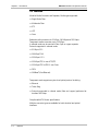
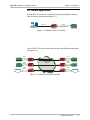
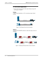
AMC-101
Universal Media Converter and Repeater
Installation and Operation Manual
Notice
This manual contains information that is proprietary to RAD Data Communications. No part of this
publication may be reproduced in any form whatsoever without prior written approval by RAD Data
Communications.
No representation or warranties for fitness for any purpose other than what is specifically mentioned in
this manual is made either by RAD Data Communications or its agents.
For further information contact RAD Data Communications at the address below or contact your local
distributor.
RAD data communications
Headquarters
12 Hanechoshet Street
Tel Aviv 69710 Israel
Tel: 972-3-6458181
Fax: 972-3-6498250
E-mail: rad@rad.co.il
RAD data communications
US East
900 Corporate Drive
Mahwah, NJ 07430 USA
Tel: (201) 529-1100
Fax: (201) 529-5777
E-mail: market@radusa.com
© 2000 RAD Data Communications
RAD data communications
US West
3631 South Harbor Boulevard
Suite 250
Santa Ana, CA 92704
Tel: (714) 850-0555
Fax: (714) 850-1555
Publication No. 333-200-06/00
Warranty
This RAD product is warranted against defects in material and workmanship for a period of one year
from date of shipment. During the warranty period, RAD will, at its option, either repair or replace
products which prove to be defective. For warranty service or repair, this product must be returned to
a service facility designated by RAD. Buyer shall prepay shipping charges to RAD and RAD shall pay
shipping charges to return the product to Buyer. However, Buyer shall pay all shipping charges, duties
and taxes for products returned to RAD from another country.
Limitation of Warranty
The foregoing warranty shall not apply to defects resulting from improper or inadequate maintenance
by Buyer, Buyer-supplied firmware or interfacing, unauthorized modification or misuse, operation
outside of the environmental specifications for the product, or improper site preparation or
maintenance.
Exclusive Remedies
The remedies provided herein are the Buyer’s sole and exclusive remedies. RAD shall not be liable for
any direct, indirect special, incidental, or consequential damages, whether based on contract, tort, or
any legal theory.
Safety Warnings
The exclamation point within a triangle is intended to warn the operator or service
personnel of operation and maintenance factors relating to the product and its
operating environment which could pose a safety hazard.
Always observe standard safety precautions during installation, operation and maintenance of this
product. Only qualified and authorized service personnel should carry out adjustment, maintenance or
repairs to this instrument. No adjustment, maintenance or repairs should be performed by either the
operator or the user.
Telecommunication Safety
The safety status of each of the ports on the AMC-101 is declared according to EN 41003 and is
detailed in the table below:
Safety Status
SELV*
TNV**
TNV operating within the limits of SELV
Limited current
ELV***
Excessive voltage
*
**
***
Ports
V.11, V.24, V.35, V.36, X.21, X.50, LAN
FXO, FXS, E&M
ISDN, E1, T1, sub E1, sub T1, various outputs to
modem
None
None
None
SELV = Safety Extra-Low Voltage
TNV = Telecommunications Network Voltage
ELV = Extra-Low Voltage
Regulatory Information
FCC-15 User Information
This equipment has been tested and found to comply with the limits of the Class A digital device,
pursuant to Part 15 of the FCC rules. These limits are designed to provide reasonable protection against
harmful interference when the equipment is operated in a commercial environment. This equipment
generates, uses and can radiate radio frequency energy and, if not installed and used in accordance
with the instruction manual, may cause harmful interference to the radio communications. Operation
of this equipment in a residential area is likely to cause harmful interference in which case the user will
be required to correct the interference at his own expense.
Warning per EN 55022
This is a Class A product. In a domestic environment, this product may cause radio interference, in
which case the user may be required to take adequate measures.
Declaration of Conformity
Manufacturer’s Name:
RAD Data Communications Ltd.
Manufacturer’s Address:
12 Hanechoshet St.
Tel Aviv 69710
Israel
declares that the product:
Product Name:
AMC-101
Conforms to the following standard(s) or other normative document(s):
EMC:
Safety:
EN 55022 (1994)
Limits and methods of measurement of radio disturbance
characteristics of information technology equipment.
EN 50082-1 (1992)
Electromagnetic compatibility - Generic immunity standards
for residential, commercial and light industry.
EN 60950 (1992/93)
Safety of information technology equipment, including
electrical business equipment.
Supplementary Information:
The product herewith complies with the requirements of the EMC Directive 89/336/EEC and the Low
Voltage Directive 73/23/EEC. The product was tested in a typical configuration.
Tel Aviv, October 10th, 1996
Haim Karshen
VP Quality
European Contact: RAD Data Communications GmbH, Lyoner Strasse 14, 60528 Frankfurt am Main, Germany
Contents
CHAPTER 1 – INTRODUCTION
1.1 General ............................................................................................................................................. 1-1
Retimed Modules ................................................................................................................................. 1-1
Transparent Modules ............................................................................................................................ 1-1
1.2 Features ............................................................................................................................................ 1-2
1.3 General Applications......................................................................................................................... 1-3
1.4 Fast Ethernet Applications................................................................................................................. 1-6
1.5 Specifications .................................................................................................................................. 1-10
Indicators ........................................................................................................................................... 1-10
Controls.............................................................................................................................................. 1-10
Power................................................................................................................................................. 1-10
Physical .............................................................................................................................................. 1-10
Environment ....................................................................................................................................... 1-10
CHAPTER 2 – INSTALLATION & SETUP
2.1 Unpacking......................................................................................................................................... 2-1
Before Unpacking ................................................................................................................................. 2-1
Unpacking Procedure ........................................................................................................................... 2-1
2.2 Site Requirements ............................................................................................................................. 2-1
Power................................................................................................................................................... 2-1
Front and Rear Panel Clearance ............................................................................................................ 2-1
Ambient Requirements ......................................................................................................................... 2-1
Installation of a Single Unit.................................................................................................................... 2-2
Installation of Two Units ....................................................................................................................... 2-3
2.3 Cable Connections ............................................................................................................................ 2-4
AC Power Connection .......................................................................................................................... 2-4
Grounding ............................................................................................................................................ 2-4
2.4 AMC-101 Modules ............................................................................................................................ 2-5
MM/SC/13/R Module............................................................................................................................ 2-5
MM/SC/13/T Module ............................................................................................................................ 2-6
MM/ST/13/R Module ............................................................................................................................ 2-7
MM/ST/13/T Module ............................................................................................................................ 2-8
SM/ST/13/R Module.............................................................................................................................. 2-9
SM/ST/13/T Module............................................................................................................................ 2-10
SM/FC/13/T Module ........................................................................................................................... 2-11
SM/ST/13L/R Module.......................................................................................................................... 2-12
SM/ST/13L/T Module .......................................................................................................................... 2-13
SM/SC/13L/R Module ......................................................................................................................... 2-14
AMC-101 Installation and Operation Manual
i
Contents
SM/ST/13LH/R Module ....................................................................................................................... 2-15
SM/FC/13LH/R Module....................................................................................................................... 2-16
SM/ST/15L/R Module.......................................................................................................................... 2-17
SM/ST/15LH/R Module ....................................................................................................................... 2-18
SM/FC/15LH/R Module....................................................................................................................... 2-19
MM/ST/85/T Module .......................................................................................................................... 2-20
SF1/ST/R Module ................................................................................................................................ 2-21
SF2/ST/R Module ................................................................................................................................ 2-22
SF1/FC/R Module................................................................................................................................ 2-23
SF2/FC/R Module................................................................................................................................ 2-24
CX/BNC/155/R Module....................................................................................................................... 2-25
CX/DIN/155/R Module ....................................................................................................................... 2-26
STP/155/R Module.............................................................................................................................. 2-27
STP/155/T Module.............................................................................................................................. 2-28
UTP/155/R Module............................................................................................................................. 2-29
UTP/155/T Module............................................................................................................................. 2-30
UTP/100/R Module............................................................................................................................. 2-31
UTP/100/T Module............................................................................................................................. 2-32
100BT/B Module ................................................................................................................................ 2-33
100BT/R Module ................................................................................................................................ 2-34
10BT/B Module .................................................................................................................................. 2-35
CHAPTER 3 – OPERATION
3.1 Controls and Indicators .................................................................................................................... 3-1
3.2 Dry Contact Circuit and Connector for Alarms................................................................................. 3-3
3.3 Turning On AMC-101 ....................................................................................................................... 3-4
3.4 Normal Operation ............................................................................................................................ 3-5
3.5 Turning Off AMC-101 ....................................................................................................................... 3-5
3.6 Troubleshooting Procedures............................................................................................................. 3-5
The POWER LED does not light ............................................................................................................ 3-5
Data transmission difficulties ................................................................................................................. 3-5
ii
AMC-101 Installation and Operation Manual
Contents
List of Figures
Figure 1-1 Dissimilar Device Connectivity .................................................................................................. 1-3
Figure 1-2 Dual Similar Device Connectivity............................................................................................... 1-3
Figure 1-3 WRAP: Dual Single Mode (SM) to Multimode (MM) Conversion ............................................... 1-4
Figure 1-4 Single Interface SM to MM (Wrap) ............................................................................................. 1-4
Figure 1-5 FDDI and Fast Ethernet Operations............................................................................................ 1-5
Figure 1-6 Half Duplex Point-to-Point Connection...................................................................................... 1-6
Figure 1-7 Extending Half Duplex Point-to-Point Connection...................................................................... 1-6
Figure 1-8 Repeater Half Duplex Connection over UTP .............................................................................. 1-7
Figure 1-9 Extending Repeater Half Duplex Connection ............................................................................. 1-7
Figure 1-10 Point-to-Point Full Duplex Connection..................................................................................... 1-8
Figure 1-11 Extending Point-to-Point Full Duplex Connection..................................................................... 1-8
Figure 1-12 Full Duplex Connection over UTP........................................................................................... 1-9
Figure 1-13 Extending Full Duplex Connection ........................................................................................... 1-9
Figure 2-1 AMC-101 Rear Panel AC Version............................................................................................... 2-2
Figure 2-2 AMC-101 Rear Panel DC Version .............................................................................................. 2-2
Figure 2-3 Installation of a Single Unit ........................................................................................................ 2-2
Figure 2-4 Installation of Two Units (a) ....................................................................................................... 2-3
Figure 2-5 Installation of Two Units (b) ....................................................................................................... 2-4
Figure 2-6 MM/SC/13/R Module Front Panel .............................................................................................. 2-5
Figure 2-7 MM/SC/13/T Module Front Panel .............................................................................................. 2-6
Figure 2-8 MM/ST/13/R Module Front Panel............................................................................................... 2-7
Figure 2-9 MM/ST/13/T Module Front Panel............................................................................................... 2-8
Figure 2-10 SM/ST/13/R Module Front Panel .............................................................................................. 2-9
Figure 2-11 SM/ST/13/T Module Front Panel ............................................................................................ 2-10
Figure 2-12 SM/FC/13/T Module Front Panel............................................................................................ 2-11
Figure 2-13 SM/ST/13L/R Module Front Panel .......................................................................................... 2-12
Figure 2-14 SM/ST/13L/T Module Front Panel .......................................................................................... 2-13
Figure 2-15 SM/SC/13L/R Module Front Panel.......................................................................................... 2-14
Figure 2-16 SM/ST/13LH/R Module Front Panel ....................................................................................... 2-15
Figure 2-17 SM/FC/13LH/R Module Front Panel ....................................................................................... 2-16
Figure 2-18 SM/ST/15L/R Module Front Panel .......................................................................................... 2-17
Figure 2-19 SM/ST/15LH/R Module Front Panel ....................................................................................... 2-18
Figure 2-20 SM/FC/15LH/R Module Front Panel ....................................................................................... 2-19
Figure 2-21 MM/ST/85/T Module Front Panel........................................................................................... 2-20
Figure 2-22 SF1/ST/R Module Front Panel ................................................................................................ 2-21
Figure 2-23 SF2/ST/R Module Front Panel ................................................................................................ 2-22
Figure 2-24 SF1/FC/R Module Front Panel ................................................................................................ 2-23
Figure 2-25 SF2/FC/R Module Front Panel ................................................................................................ 2-24
Figure 2-26 CX/BNC/155/R Module Front Panel ....................................................................................... 2-25
Figure 2-27 CX/DIN/155/R Module Front Panel ........................................................................................ 2-26
Figure 2-28 STP/155/R Module Front Panel .............................................................................................. 2-27
Figure 2-29 STP/155/T Module Front Panel .............................................................................................. 2-28
Figure 2-30 UTP/155/R Module Front Panel ............................................................................................. 2-29
Figure 2-31 UTP/155/T Module Front Panel ............................................................................................. 2-30
Figure 2-32 UTP/100/R Module Front Panel ............................................................................................. 2-31
Figure 2-33 UTP/100/T Module Front Panel ............................................................................................. 2-32
Figure 2-34 100BT/B Module Front Panel................................................................................................. 2-33
Figure 2-35 100BT/R Module Front Panel................................................................................................. 2-34
AMC-101 Installation and Operation Manual
iii
List of Tables
Figure 2-36 10BT/B Module Front Panel................................................................................................... 2-35
Figure 3-1 AMC-101 Front Panel................................................................................................................ 3-1
Figure 3-2 Jumper Locations and Functions ................................................................................................ 3-2
Figure 3-3 Connector Pin Assignment .......................................................................................................... 3-3
Figure 3-4 AMC-101 Block Diagram........................................................................................................... 3-4
List of Tables
Table 1-1
Table 1-2
Table 1-3
Table 2-1
Table 2-2
Table 2-3
Table 2-4
Table 2-5
Table 2-6
Table 2-7
Table 2-8
Table 2-9
Table 3-1
Table 3-2
Table 3-3
Table 3-4
iv
Optical Module Characteristics .................................................................................................. 1-11
Electrical Module Characteristics ................................................................................................ 1-13
Bridging Modules ...................................................................................................................... 1-13
STP/155/R Pinout ...................................................................................................................... 2-27
STP/155/T Pinout ...................................................................................................................... 2-28
UTP/155/R Pinout ..................................................................................................................... 2-29
UTP/155/T Pinout ..................................................................................................................... 2-30
UTP/100/R Pinout ..................................................................................................................... 2-31
UTP/100/T Pinout ..................................................................................................................... 2-32
100BT/B Module Pinout ............................................................................................................ 2-33
100BT/R Module Pinout ............................................................................................................ 2-34
10BT/B Module Pinout .............................................................................................................. 2-35
AMC-101 Front Panel Indicators .................................................................................................. 3-1
AMC-101 Front Panel Controls .................................................................................................... 3-1
Functions and Settings ................................................................................................................. 3-2
Connector Pin Assignment ........................................................................................................... 3-3
AMC-101 Installation and Operation Manual
Chapter 1
Introduction
1.1 General
The AMC-101, a Universal Converter and Repeater, provides retimed or
transparent conversion of optical and electrical signals for ATM, FDDI, Fast
Ethernet and other protocols at data rates up to 155 Mbps. The modularity
of the AMC-101 interfaces enables field-changeable conversion between
any two media.
Transparent modules provide cost-effective media conversion without
reclocking. Retimed modules provide media conversion with reclocking,
which enables the AMC-101 to be used as a repeater. These modules can
also be set for transparent operation.
AMC-101 is supplied as a standalone unit. Special hardware for mounting
either a single unit or two units side-by-side in a 19" rack can be ordered
separately.
Retimed Modules
The AMC-101 provides retimed media conversion for the following ATM
interfaces:
•
TAXI (100 Mbps)
•
STM-1
•
STS-3c
•
STS-1 over optical and electrical interfaces.
Retimed conversion is also available for FDDI and Fast Ethernet between
single mode and multimode fiber, and for extending FDDI UTP
connections over fiber. The retimed modules provide rate selection for 51,
100 or 155 Mbps. When set to one of these rates, the retimed module
regenerates and reclocks the incoming signal and acts as an ATM or FDDI
repeater. When the switch is set to "OTHER", the modules regenerate the
signal without reclocking as transparent modules do.
Transparent
Modules
The AMC-101 provides transparent conversion for any two-level optical
protocol. Transparent modules are recommended for short distances and
for all fiber and copper applications at less than 100 Mbps.
A special WRAP button activates loopbacks at the two interfaces. This can
be used for test purposes or for special applications as explained later.
General
1-1
AMC-101 Installation & Operation Manual
Chapter 1 - Introduction
1.2 Features
Modular Media Converter and Repeater, Media types supported:
•
Single Mode Fiber
•
Multimode Fiber
•
STP
•
UTP
•
Coax
Retimed media conversion for 51 Mbps, 100 Mbps and 155 Mbps.
Transparent media conversion up to 155 Mbps.
In retimed mode can be used as a Fiber Optic or copper repeater
Protocols supported in retimed mode:
•
51 Mbps OC-1
•
100 Mbps TAXI
•
155 Mbps OC-3
•
155 Mbps STS-3c over UTP/STP
•
155 Mbps STS-3c/STM-1 over Coax
•
FDDI
•
100BaseT (Fast Ethernet).
Transparent mode supports any two-level optical protocol including:
•
Ethernet
•
Token Ring
•
Protocols supported in retimed mode (fiber and copper) performed at
less than 100 Mbps.
Complies with ATM forum specifications.
Multiple connector types are available for both electrical and optical
interfaces.
1-2
Features
AMC-101 Installation & Operation Manual
Chapter 1 - Introduction
1.3 General Applications
A single AMC-101 is used to connect two devices operating with different
fiber or electrical interfaces (see Figure 1-1).
UTP Cat 5
1300 nm
155 Mbps
ATM Station
Single Mode Fiber
AMC-101
ATM Switch
Figure 1-1 Dissimilar Device Connectivity
A pair of AMC-101s connect two similar devices over different media types
(see Figure 1-2).
Coax
155 Mbps
Coax
155 Mbps
AMC-101
ATM Switch
MMF
1300 nm
PTT Single Mode
1300 nm
AMC-101
FDDI
AMC-101
MMF
1300 nm
AMC-101
MMF
850 nm
FDDI
MMF
850 nm
Token Ring
AMC-101
ATM Switch
Token Ring
AMC-101
Figure 1-2 Dual Similar Device Connectivity
General Applications
1-3
AMC-101 Installation & Operation Manual
Chapter 1 - Introduction
A single AMC-101 in WRAP mode can be used for double conversion
between single mode and multimode fiber for a dual attached FDDI station
or concentrator (see Figure 1-3).
Figure 1-3 WRAP: Dual Single Mode (SM) to Multimode (MM) Conversion
A single AMC-101 equipped with a single interface in WRAP mode can be
used for conversion between single mode and multimode fiber
(see Figure 1-4).
1300 nm Multimode
1300 nm Single Mode
ATM Switch
ATM Switch
AMC-101
in WRAP Mode
Figure 1-4 Single Interface SM to MM (Wrap)
1-4
General Applications
AMC-101 Installation & Operation Manual
Chapter 1 - Introduction
The FDDI applies scrambling to data when operating over UTP, but not
doing so when operating over fiber. Because of this, AMC-101 can only
work in pairs for extending FDDI connections over fiber (see Figure 1-5).
Fiber
UTP Cat 5
FDDI
AMC-101
UTP Cat 5
AMC-101
FDDI
Figure 1-5 FDDI and Fast Ethernet Operations
General Applications
1-5
AMC-101 Installation & Operation Manual
Chapter 1 - Introduction
1.4 Fast Ethernet Applications
•
Point to Point Link using a pair of Fiber Optic Cables running in HD
(Half Duplex) 100-BaseFX:
Problem:
In a point to point application, in HD, the maximum range is limited
to 412m.
Fiber Optic Link
Up to 412m
Server
Printer
Fiber Optic Link
Up to 412m
Laptop
PC
Figure 1-6 Half Duplex Point-to-Point Connection
Solution:
Using two AMC-M/100BT/B modules can extend the range up to tens of
kilometers.
Fiber Optic Link
UTP
Server
AMC-101
with AMC-M/100BT/B
AMC-101
with AMC-M/100BT/B
Fiber Optic Link
UTP
PC
UTP
Up to tens of kilometers
Printer
UTP
Up to tens of kilometers
AMC-101
with AMC-M/100BT/B
AMC-101
with AMC-M/100BT/B
Laptop
Figure 1-7 Extending Half Duplex Point-to-Point Connection
1-6
Fast Ethernet Applications
AMC-101 Installation & Operation Manual
•
Chapter 1 - Introduction
Repeater based LAN Link using standard UTP at HD (Half Duplex).
Problem:
Range is limited to 100m from the repeater.
UTP
Up to 100m
Fast Ethernet Station
(Laptop)
Repeater
UTP
Up to 100m
Fast Ethernet Station
Figure 1-8 Repeater Half Duplex Connection over UTP
Solution:
Using two AMC-101s with AMC-M/100BT/B modules can extend the range
up to tens of kilometers.
UTP
Up to 100m
Fast Ethernet Station
(Laptop)
Repeater
UTP < 80m
Fiber Optic Link
UTP < 80m
Up to tens of kilometers
AMC-101
AMC-101
Fast Ethernet Station
with AMC-M/100BT/B Module
with AMC-M/100BT/B Module
Figure 1-9 Extending Repeater Half Duplex Connection
Fast Ethernet Applications
1-7
AMC-101 Installation & Operation Manual
Chapter 1 - Introduction
•
Extension of a point to point FD (Full Duplex) Fast Ethernet connection:
Problem:
The distance between two FD stations running on UTP needs to be
extended.
UTP
Up to 100m
FD Fast Ethernet Station
FD Fast Ethernet Station
Figure 1-10 Point-to-Point Full Duplex Connection
Solution:
Using two AMC-101s with AMC-M/100BT/R modules can extend the range
up to tens of kilometers.
FD Fiber Optic Link
UTP
UTP
Up to 80m
Up to 80m
Up to tens of kms
FD Fast Ethernet Station
FD Fast Ethernet Station
AMC-101 with
AMC-101 with
AMC-M/100BT/R Module
AMC-M/100BT/R Module
Figure 1-11 Extending Point-to-Point Full Duplex Connection
1-8
Fast Ethernet Applications
AMC-101 Installation & Operation Manual
•
Chapter 1 - Introduction
Extension of a Switched Based Fast Ethernet LAN (FD - Full Duplex)
Problem:
The range of a FD Fast Ethernet LAN running on UTP has to be extended.
UTP
Up to 100m
IBM Printer
UTP
Up to 100m
Fast Ethernet Laptop Station
FD Fast Ethernet Switch
UTP
Up to 100m
Fast Ethernet Station
Figure 1-12 Full Duplex Connection over UTP
Solution:
Using AMC-101s with AMC-M/100BT/R modules can extend the range up
to tens of kilometers.
Fiber Optic Link
Up to tens of kilometers
Printer with
Fiber Optic Transceiver
Running FD Fast Ethernet
AMC-101
with AMC-M/100BT/R Module
UTP < 80m
UTP
Up to 100m
UTP < 80m
FD Fast
Ethernet Switch
FD Fast Ethernet Station
(Laptop)
Fiber Optic Link
UTP < 80m
AMC-101
FD Fast Ethernet Station
with AMC-M/100BT/R Module
Up to tens of kilometers
AMC-101
with AMC-M/100BT/R Module
Figure 1-13 Extending Full Duplex Connection
Specifications
1-9
AMC-101 Installation & Operation Manual
Chapter 1 - Introduction
1.5 Specifications
Indicators
Controls
Power
Physical
Environment
1-10
Specifications
Data Rate
Up to 155 Mbps
POWER (PWR)
ON when unit is powered
FAULT (FLT)
BLINKS when card configuration is wrong
WRAP
ON when the two interfaces are wrapped
SIG
ON when received signal from Rx is valid
BLINKS when the PLL is out of lock
WRAP
For double conversion or test purposes
RATE
For data rate selection 51, 100, 155 Mbps
OTHER
For transparent mode
AC source
90-260 VAC, 16 ± 0.4 Watts,
47-63 Hz
DC source
-48 VDC
Height
4.4 cm / 1.8 in (1U)
Width
21.6 cm / 8.5 in
Depth
24.2 cm / 9.5 in
Weight
1.1 kg / 2.8 lb
Temperature
0o-50oC/32o-122oF
Humidity
Up to 95%, non-condensing
AMC-101 Installation & Operation Manual
Chapter 1 - Introduction
Table 1-1 Optical Module Characteristics
Module Name
MM/ST/85*
MM/SC/13**
MM/ST/13**
SF1/FC***
SF2/FC***
SF1/ST***
SF2/ST***
SM/FC/13**
SM/FC/13L**
(LASER)
Protocols
Supported
Fiber Type Connector Typical Dynamic
(Wavelength)
Type
Distance
Range
Optical Sensitivity
Power
(Typical)
Token Ring,
Ethernet only
62.5/125
(850 nm)
ST
18 dB
-18 dBm
-30 dBm
TAXI, FDDI,
Fast Ethernet,
STS-1, STS3c/STM-1
62.5/125
(1300 nm)
SC
17 dB
-18 dBm
-31 dBm
TAXI, FDDI,
62.5/125
Fast Ethernet (1300 nm)
STS-3c/STM-1,
STS-1
ST
17 dB
-18 dBm
-31 dBm
TAXI, FDDI,
9/125
Fast Ethernet,
Transmit
STS-3c/STM-1,
1300 nm
STS-1
Receive
1550 nm
FC-PC
40 Km /
28 dB
-12 dBm
-29 dBm
(Single
Strand)
24.8 mile
TAXI, FDDI,
9/125
Fast Ethernet,
Transmit
STS-3c/STM-1,
1550 nm
STS-1
Receive
1300 nm
FC-PC
40 Km /
28 dB
-12 dBm
-29 dBm
(Single
Strand)
24.8 mile
TAXI, FDDI,
9/125
Fast Ethernet,
Transmit
STS-3c/STM-1,
1300 nm
STS-1
Receive
1550 nm
ST
40 Km /
28 dB
-12 dBm
-29 dBm
(Single
Strand)
24.8 mile
TAXI, FDDI,
9/125
Fast Ethernet,
Transmit
STS-3c/STM-1,
1550 nm
STS-1
Receive
1300 nm
ST
40 Km /
28 dB
-12 dBm
-29 dBm
(Single
Strand)
24.8 mile
TAXI, FDDI,
9/125
Fast Ethernet,
1300 nm
STS-3c/STM-1/
STS-1
FC-PC
25 Km /
30 dB
-15 dBm
-31 dBm
TAXI, FDDI,
9/125
Fast Ethernet,
1300 nm
STS-3c/STM-1/
STS-1
FC-P
30 dB
-12 dBm
-31 dBm
2 Km /
1.2 mile
2 Km /
1.2 mile
2 Km /
1.2 mile
15.5 mile
40 Km /
24.8 mile
Specifications
1-11
AMC-101 Installation & Operation Manual
Chapter 1 - Introduction
Table 1-1 Optical Module Characteristics (Cont.)
Module Name
Protocols
Supported
Fiber Type Connector Typical Dynamic
(Wavelength)
Type
Distance
Range
SM/FC/13LH*** TAXI, FDDI,
9/125
(LASER)
Fast Ethernet
(1300 nm)
STS-3c/STM-1,
STS-1
FC-PC
SM/FC/15LH*** TAXI, FDDI,
9/125
(LASER)
Fast Ethernet
(1550 nm)
STS-3c/STM-1,
STS-1
FC-PC
SM/SC/13L**
(LASER)
TAXI, FDDI,
9/125
Fast Ethernet, (1300 nm)
STS-3c/STM-1,
STS-1
SC
SM/ST/13**
TAXI, FDDI,
9/125
Fast Ethernet, (1300 nm)
STS-3c/STM-1,
STS-1
ST
TAXI, FDDI,
9/125
Fast Ethernet, (1300 nm)
STS-3c/STM-1,
STS-1
ST
SM/ST/13LH*** TAXI, FDDI,
9/125
(LASER)
Fast Ethernet, (1300 nm)
STS-3c/STM-1,
STS-1
ST
SM/ST/15L**
(LASER)
TAXI, FDDI,
9/125
Fast Ethernet, (1500 nm)
STS-3c/STM-1,
STS-1
ST
SM/ST/15LH*** TAXI, FDDI,
9/125
(LASER)
Fast Ethernet, (1550 nm)
STS-3c/STM-1,
STS-1
ST
SM/ST/13L**
(LASER)
60 Km /
Optical Sensitivity
Power
(Typical)
33 dB
-2 dBm
-34 dBm
33 dB
-2 dBm
-34 dBm
30 dB
-12 dBm
-31 dBm
30 dB
-15 dBm
-31 dBm
30 dB
-12 dBm
-31 dBm
33 dB
-2 dBm
-34 dBm
30 dB
-12 dBm
-31 dBm
33 dB
-2 dBm
-34 dBm
37.2 mile
110 Km /
68.2 mile
40 Km /
24.8 mile
25 Km /
15.5 mile
40 Km /
24.8 mile
60 Km /
37.2 mile
50 Km /
31 mile
110 Km /
68.2 mile
* Data Rates are switch-selectable from the front panel
** Transparent only
*** Retimed only
Note
1-12
Specifications
Typical distances based on attenuation of 0.4 dB/Km for 1300 nm modules
and 0.25 dB/Km for 1550 nm modules
AMC-101 Installation & Operation Manual
Chapter 1 - Introduction
Table 1-2 Electrical Module Characteristics
Module Name
Protocols
Supported
Cable Type
Connector
Type
Range
Impedance
(Ohms)
UTP/155*
STS-3c
UTP Cat 5
Shielded RJ-45
100 m
100
STP/155*
STS-3c
STP Type 1
DB-9
100 m
150
UTP/100*
FDDI,
UTP Cat 5
Shielded RJ-45
100 m
100
CX/BNC/155**
STS-3c STM-1
Coax
BNC
12.7 dB*
75
CX/DIN/155**
STS-3c STM-1
Coax
DIN 47295 1.6/5.6 Coaxial
connector
12.7 dB*
75
* 50 m in transparent module
** Retimed only, 135 m is attainable when using RG-59 B/U cable (At 78 MHz, according to square root of
frequency law)
Table 1-3 Bridging Modules
Module Name
Protocols
Supported
Cable Type
Connector
Type
Range
Impedance
(Ohms)
10BT/B*
Ethernet
UTP Cat 5
Shielded RJ-45
100 m
100
100BT/B**
Fast Ethernet
UTP Cat 5
Shielded RJ-45
80 m
100
100BT/R***
Fast Ethernet
UTP Cat 5
Shielded RJ-45
80 m
100
* Remote Ethernet bridge module
** Remote Fast Ethernet bridge module
*** Media Converter for Fast Ethernet (Tx to Fx)
Specifications
1-13
Chapter 1 - Introduction
1-14
Specifications
AMC-101 Installation & Operation Manual
Chapter 2
Installation & Setup
2.1 Unpacking
Before Unpacking Inspect the equipment container before unpacking. Note and report
evidence of damage immediately.
Unpacking
Procedure
•
Place the container on a clean flat surface. Cut all straps and open or
remove top.
•
Remove the unit carefully and place it securely on a clean surface.
•
Remove all packing material.
•
Inspect the unit for damage. Report any damage immediately.
2.2 Site Requirements
Power
AMC-101 is powered by 100 to 240 VAC or -48 VDC.
The unit should be installed within 1.5m (5 ft) of an easily accessible
grounded AC outlet capable of supplying 230 V (115 V).
Front and Rear
Panel Clearance
Allow at least 90 cm (36 in) of clearance at the front of the unit for operator
access. Allow at least 10 cm (4 in) clearance at the rear of the unit for power
cord connection.
Ambient
Requirements
The ambient operating temperature of AMC-101 should be 0-40oC
(32-122oF) at a relative humidity of up to 90%, non-condensing.
Site Requirements
2-1
Chapter 2 - Installation & Setup
AMC-101 Installation & Operation Manual
Figure 2-1 AMC-101 Rear Panel AC Version
Figure 2-2 AMC-101 Rear Panel DC Version
Installation of a
Single Unit
Rack adapter components for installing a single unit include one short
bracket and one long bracket. Each bracket is fastened to the side walls of
the unit by two screws (with flat washers) which are inserted into the two
front holes on the side wall (The unit is supplied with nuts already in place
on the inner side wall). Note that the short bracket fastens to the left side of
the unit, and the long bracket to the right side of the unit (see Figure 2-3).
Once the brackets are fastened to the side walls, the unit is ready for
installation in the 19" rack. Place the unit in the rack and fasten the brackets
to the side rails of the rack by means of the two screws situated on each side
(not included in the kit).
Figure 2-3 Installation of a Single Unit
2-2
Site Requirements
AMC-101 Installation & Operation Manual
Installation of
Two Units
Chapter 2 - Installation & Setup
Rack adapter components for installing two units include two long side rails
(one for each unit) which slide one into the other fastening the two units
together, and two short side brackets which hold the two units in the
19'' rack (see Figure 2-4).
Figure 2-4 Installation of Two Units (a)
To install two units follow these instructions:
1. Fasten one long side rail to each unit (right side to one unit, left side to
the other unit) using the four screws and flat washers supplied. The side
rails must be attached in opposing fashion, the narrow flange of the first
rail opposite the wide flange of the second rail.
2. Attach one short bracket opposite the side rail on each unit using the
four screws and flat washers supplied.
3. Slide the side rail of one unit into the side rail of the other unit, fastening
the two units together (see Figure 2-5).
4. Secure the supplied plastic caps to the ends of the rails, to prevent the
units moving and to protect the rail ends.
5. Place the assembled units in the rack and fasten the brackets to the side
rails of the rack, by means of the four screws situated on each side
(not included in the kit).
Site Requirements
2-3
AMC-101 Installation & Operation Manual
Chapter 2 - Installation & Setup
Figure 2-5 Installation of Two Units (b)
2.3 Cable Connections
AC Power
Connection
Warning
AC power should be supplied to AMC-101 through a 1.5m (5 ft) standard
power cord terminated by a grounded 3-wire plug.
When applying AC power, first connect the plug of the AC cable to the
power connector on the rear panel of AMC-101 and then to the mains
outlet.
Grounding
Warning
2-4
AMC-101 Modules
Interrupting of the protective (grounding) conductor (inside or outside
the instrument) or disconnecting the protective earth terminal can make
this instrument dangerous. Intentional interruption of the grounding
conductor is prohibited.
AMC-101 Installation & Operation Manual
Chapter 2 - Installation & Setup
2.4 AMC-101 Modules
The upper part of the module front panel is AMC-R for a Retimed Timing
mode; the lower part is AMC-T for a Transparent Timing mode. In both
panels, the module name is labeled at panel’s bottom.
MM/SC/13/R Module
Figure 2-6 MM/SC/13/R Module Front Panel
Wavelength:
1300 nm
Connector:
SC
Used with:
Multimode fiber
Protocols supported:
STS-3c, STM-1, STS-1, FDDI, TAXI and
Fast Ethernet
Timing mode:
Retimed
Coding method:
4B/5B, NRZ
Optical output into 62.5/125 fiber:
-18 dBm
Receiver sensitivity:
-31 dBm
Maximum input power:
-14 dBm
AMC-101 Modules
2-5
AMC-101 Installation & Operation Manual
Chapter 2 - Installation & Setup
MM/SC/13/T Module
Figure 2-7 MM/SC/13/T Module Front Panel
2-6
AMC-101 Modules
Wavelength:
1300 nm
Connector:
SC
Used with:
Multimode fiber
Protocols supported:
Any two level optical protocols up to
155 Mbps
Timing mode:
Transparent
Coding method:
4B/5B, NRZ
Optical output into 62.5/125 fiber:
-18 dBm
Receiver sensitivity:
-31 dBm
Maximum input power:
-14 dBm
AMC-101 Installation & Operation Manual
Chapter 2 - Installation & Setup
MM/ST/13/R Module
Figure 2-8 MM/ST/13/R Module Front Panel
Wavelength:
1300 nm
Connector:
ST
Used with:
Multimode fiber
Protocols supported:
STS-3c, STM-1, STS-1, FDDI, TAXI and Fast
Ethernet
Timing mode:
Retimed
Coding method:
4B/5B, NRZ
Optical output into 62.5/125 fiber:
-18 dBm
Receiver sensitivity:
-31 dBm
Maximum input power:
-14 dBm
AMC-101 Modules
2-7
AMC-101 Installation & Operation Manual
Chapter 2 - Installation & Setup
MM/ST/13/T Module
Figure 2-9 MM/ST/13/T Module Front Panel
2-8
AMC-101 Modules
Wavelength:
1300 nm
Connector:
ST
Used with:
Multimode fiber
Protocols supported:
Any two level optical protocols up to
155 Mbps
Timing mode:
Transparent
Coding method:
4B/5B, NRZ
Optical output into 62.5/125 fiber:
-18 dBm
Receiver sensitivity:
-31 dBm
Maximum input power:
-14 dBm
AMC-101 Installation & Operation Manual
Chapter 2 - Installation & Setup
SM/ST/13/R Module
Figure 2-10 SM/ST/13/R Module Front Panel
Wavelength:
1300 nm
Connector:
ST
Used with:
Single mode fiber
Protocols supported:
STS-3c, STM-1, STS-1, FDDI, TAXI and Fast
Ethernet
Timing mode:
Retimed
Coding method:
4B/5B, NRZ
Optical output into 9/125 fiber:
-15 dBm
Receiver sensitivity:
-31 dBm
Maximum input power:
-1 dBm
AMC-101 Modules
2-9
AMC-101 Installation & Operation Manual
Chapter 2 - Installation & Setup
SM/ST/13/T Module
Figure 2-11 SM/ST/13/T Module Front Panel
2-10
Wavelength:
1300 nm
Connector:
ST
Used with:
Single mode fiber
Protocols supported:
Any two level optical protocols up to
155 Mbps
Timing mode:
Transparent
Coding method:
4B/5B, NRZ
Optical output into 9/125 fiber:
-15 dBm
Receiver sensitivity:
-31 dBm
Maximum input power:
-1 dBm
AMC-101 Modules
AMC-101 Installation & Operation Manual
Chapter 2 - Installation & Setup
SM/FC/13/T Module
Figure 2-12 SM/FC/13/T Module Front Panel
Wavelength:
1300 nm
Connector:
FC
Used with:
Single mode fiber
Protocols supported:
Any two level optical protocols up to
155 Mbps
Timing mode:
Transparent
Coding method:
4B/5B, NRZ
Optical output into 9/125 fiber:
-15 dBm
Receiver sensitivity:
-31 dBm
Maximum input power:
-1 dBm
AMC-101 Modules
2-11
AMC-101 Installation & Operation Manual
Chapter 2 - Installation & Setup
SM/ST/13L/R Module
Figure 2-13 SM/ST/13L/R Module Front Panel
2-12
Wavelength:
1300 nm
Connector:
ST
Used with:
Single mode fiber
Protocols supported:
STS-3c, STM-1, STS-1, FDDI, TAXI and Fast
Ethernet
Timing mode:
Retimed
Coding method:
4B/5B, NRZ
Optical output into 9/125 fiber:
-12 dBm
Receiver sensitivity:
-31 dBm
Maximum input power:
-1 dBm
AMC-101 Modules
AMC-101 Installation & Operation Manual
Chapter 2 - Installation & Setup
SM/ST/13L/T Module
Figure 2-14 SM/ST/13L/T Module Front Panel
Wavelength:
1300 nm
Connector:
ST
Used with:
Single mode fiber
Protocols supported:
Any two level optical protocols up to
155 Mbps
Timing mode:
Transparent
Coding method:
4B/5B, NRZ
Optical output into 9/125 fiber:
-12 dBm
Receiver sensitivity:
-31 dBm
Maximum input power:
-1 dBm
AMC-101 Modules
2-13
AMC-101 Installation & Operation Manual
Chapter 2 - Installation & Setup
SM/SC/13L/R Module
Figure 2-15 SM/SC/13L/R Module Front Panel
2-14
Wavelength:
1300 nm
Connector:
SC
Used with:
Single mode fiber
Protocols supported:
STS-3c; STM-1, STS-1, FDDI, TAXI and Fast
Ethernet
Timing mode:
Retimed
Coding method:
4B/5B, NRZ
Optical output into 9/125 fiber:
-12 dBm
Receiver sensitivity:
-31 dBm
Maximum input power:
-1 dBm
AMC-101 Modules
AMC-101 Installation & Operation Manual
Chapter 2 - Installation & Setup
SM/ST/13LH/R Module
Figure 2-16 SM/ST/13LH/R Module Front Panel
Wavelength:
1300 nm
Connector:
ST
Used with:
Single mode fiber
Protocols supported:
STS-3c; STM-1, STS-1, FDDI, TAXI and Fast
Ethernet
Timing mode:
Retimed
Coding method:
4B/5B, NRZ
Optical output into 9/125 fiber:
-2 dBm
Receiver sensitivity:
-34 dBm
Maximum input power:
-1 dBm
AMC-101 Modules
2-15
Chapter 2 - Installation & Setup
AMC-101 Installation & Operation Manual
SM/FC/13LH/R Module
Figure 2-17 SM/FC/13LH/R Module Front Panel
2-16
Wavelength:
1300 nm
Connector:
FC
Used with:
Single mode fiber
Protocols supported:
STS-3c; STM-1, STS-1, FDDI, TAXI and Fast
Ethernet
Timing mode:
Retimed
Coding method:
4B/5B, NRZ
Optical output into 9/125 fiber:
-2 dBm
Receiver sensitivity:
-34 dBm
Maximum input power:
-1 dBm
AMC-101 Modules
AMC-101 Installation & Operation Manual
Chapter 2 - Installation & Setup
SM/ST/15L/R Module
Figure 2-18 SM/ST/15L/R Module Front Panel
Wavelength:
1550 nm
Connector:
ST
Used with:
Single mode fiber
Protocols supported:
STS-3c, STM-1, STS-1, FDDI, TAXI and Fast
Ethernet
Timing mode:
Retimed
Coding method:
4B/5B, NRZ
Optical output into 9/125 fiber:
-12 dBm
Receiver sensitivity:
-31 dBm
Maximum input power:
-1 dBm
AMC-101 Modules
2-17
Chapter 2 - Installation & Setup
AMC-101 Installation & Operation Manual
SM/ST/15LH/R Module
Figure 2-19 SM/ST/15LH/R Module Front Panel
2-18
Wavelength:
1550 nm
Connector:
ST
Used with:
Single mode fiber
Protocols supported:
STS-3c; STM-1, STS-1, FDDI, TAXI and Fast
Ethernet
Timing mode:
Retimed
Coding method:
4B/5B, NRZ
Optical output into 9/125 fiber:
-2 dBm
Receiver sensitivity:
-34 dBm
Maximum input power:
-1 dBm
AMC-101 Modules
AMC-101 Installation & Operation Manual
Chapter 2 - Installation & Setup
SM/FC/15LH/R Module
Figure 2-20 SM/FC/15LH/R Module Front Panel
Wavelength:
1550 nm
Connector:
FC
Used with:
Single mode fiber
Protocols supported:
STS-3c, STM-1, STS-1, FDDI, TAXI
and Fast Ethernet
Timing mode:
Retimed
Coding method:
4B/5B, NRZ
Optical output into 9/125 fiber:
-2 dBm
Receiver sensitivity:
-34 dBm
Maximum input power:
-1 dBm
AMC-101 Modules
2-19
AMC-101 Installation & Operation Manual
Chapter 2 - Installation & Setup
MM/ST/85/T Module
Figure 2-21 MM/ST/85/T Module Front Panel
2-20
Wavelength:
850 nm
Connector:
ST
Used with:
Multimode fiber
Protocols supported:
Token Ring, Ethernet only
Timing mode:
Transparent
Coding method:
4B/5B, NRZ, Manchester
Optical output into 62.5/125 fiber:
-18 dBm
Receiver sensitivity:
-30 dBm
Maximum Input Power
-12 dBm
AMC-101 Modules
AMC-101 Installation & Operation Manual
Chapter 2 - Installation & Setup
SF1/ST/R Module
Figure 2-22 SF1/ST/R Module Front Panel
Wavelength:
Transmit: 1300 nm; Receive: 1550 nm
Connector:
ST
Used with:
Single mode fiber
Protocols supported:
STS-3c, STM-1, STS-1, FDDI, TAXI
and Fast Ethernet
Timing mode:
Retimed
Optical output into 9/125 fiber:
-12 dBm
Receiver sensitivity:
-29 dBm
AMC-101 Modules
2-21
AMC-101 Installation & Operation Manual
Chapter 2 - Installation & Setup
SF2/ST/R Module
Figure 2-23 SF2/ST/R Module Front Panel
2-22
Wavelength:
Transmit: 1550 nm; Receice: 1300 nm
Connector:
ST
Used with:
Single mode fiber
Protocols supported:
STS-3c, STM-1, STS-1, FDDI, TAXI
and Fast Ethernet
Timing mode:
Retimed
Optical output into 9/125 fiber:
-12 dBm
Receiver sensitivity:
-29 dBm
AMC-101 Modules
AMC-101 Installation & Operation Manual
Chapter 2 - Installation & Setup
SF1/FC/R Module
Figure 2-24 SF1/FC/R Module Front Panel
Wavelength:
Transmit: 1300 nm; Receive: 1550 nm
Connector:
FC
Used with:
Single mode fiber
Protocols supported:
STS-3c, STM-1, STS-1, FDDI, TAXI
and Fast Ethernet
Timing mode:
Retimed
Optical output into 9/125 fiber:
-12 dBm
Receiver sensitivity:
-29 dBm
AMC-101 Modules
2-23
AMC-101 Installation & Operation Manual
Chapter 2 - Installation & Setup
SF2/FC/R Module
Figure 2-25 SF2/FC/R Module Front Panel
2-24
Wavelength:
Transmit: 1550 nm; Receive: 1300 nm
Connector:
FC
Used with:
Single mode fiber
Protocols supported:
STS-3c, STM-1, STS-1, FDDI, TAXI
and Fast Ethernet
Timing mode:
Retimed
Optical output into 9/125 fiber:
-12 dBm
Receiver sensitivity:
-29 dBm
AMC-101 Modules
AMC-101 Installation & Operation Manual
Chapter 2 - Installation & Setup
CX/BNC/155/R Module
Figure 2-26 CX/BNC/155/R Module Front Panel
Connector:
BNC
Used with:
Coax cable
Protocols supported:
STS-3c, STM-1
Timing mode:
Retimed
Range calculation:
12.7 dB at 78 MHz according to
square root of frequency law
Impedance:
75 Ω
AMC-101 Modules
2-25
AMC-101 Installation & Operation Manual
Chapter 2 - Installation & Setup
CX/DIN/155/R Module
Figure 2-27 CX/DIN/155/R Module Front Panel
2-26
Connector:
1.6/5.6 Coax
Used with:
Coax cable
Protocols supported:
STS-3c, STM-1
Timing mode:
Retimed
Range calculation:
12.7 dB at 78 MHz according to
square root of frequency law;
135 m is attainable when using
RG-59 B/U cables
(Cable length varies in accordance
with cable type)
Impedance:
75 Ω
AMC-101 Modules
AMC-101 Installation & Operation Manual
Chapter 2 - Installation & Setup
STP/155/R Module
Figure 2-28 STP/155/R Module Front Panel
Connector:
DB-9
Used with:
STP type 1 cable
Protocols supported:
STS-3c
Timing mode:
Retimed
Coding method:
NRZ
Range:
100 m
Impedance:
150 Ω
Table 2-1
STP/155/R Pinout
Pinout
Pin 1
Rx+
Pin 2
Pin 3
Pin 4
Pin 5
Tx+
Pin 6
Rx-
Pin 7
Pin 8
Pin 9
Tx-
AMC-101 Modules
2-27
AMC-101 Installation & Operation Manual
Chapter 2 - Installation & Setup
STP/155/T Module
Figure 2-29 STP/155/T Module Front Panel
Connector:
DB-9
Used with:
STP type 1 cable
Protocols supported:
STS-3c
Timing mode:
Transparent
Coding method:
NRZ
Range:
50 m
Impedance:
150 Ω
Table 2-2
STP/155/T Pinout
Pinout
Pin 1
Rx+
Pin 2
Pin 3
Pin 4
Pin 5
Tx+
Pin 6
Rx-
Pin 7
Pin 8
Pin 9
2-28
AMC-101 Modules
Tx-
AMC-101 Installation & Operation Manual
Chapter 2 - Installation & Setup
UTP/155/R Module
Figure 2-30 UTP/155/R Module Front Panel
Connector:
Shielded RJ-45
Used with:
UTP Cat 5
Protocols supported:
STS-3c
Timing mode:
Retimed
Coding method:
NRZ
Range:
100 m
Impedance:
100 Ω
Table 2-3
UTP/155/R Pinout
Pinout
Pin 1
Tx+
Pin 2
Tx-
Pin 3
Pin 4
Pin 5
Pin 6
Pin 7
Rx+
Pin 8
Rx-
AMC-101 Modules
2-29
AMC-101 Installation & Operation Manual
Chapter 2 - Installation & Setup
UTP/155/T Module
Figure 2-31 UTP/155/T Module Front Panel
Connector:
Shielded RJ-45
Used with:
UTP Cat 5
Protocols supported:
STS-3c
Timing mode:
Transparent
Coding method:
NRZ
Range:
50 m
Impedance:
100 Ω
Table 2-4
UTP/155/T Pinout
Pinout
Pin 1
Tx+
Pin 2
Tx-
Pin 3
Pin 4
Pin 5
Pin 6
2-30
AMC-101 Modules
Pin 7
Rx+
Pin 8
Rx-
AMC-101 Installation & Operation Manual
Chapter 2 - Installation & Setup
UTP/100/R Module
Figure 2-32 UTP/100/R Module Front Panel
Connector:
Shielded RJ-45
Used with:
UTP Cat 5
Protocols supported:
FDDI
Timing mode:
Retimed
Coding method:
NRZ
Range:
100 m
Impedance:
100 Ω
Table 2-5
UTP/100/R Pinout
Pinout
Pin 1
Tx+
Pin 2
Tx-
Pin 3
Pin 4
Pin 5
Pin 6
Pin 7
Rx+
Pin 8
Rx-
AMC-101 Modules
2-31
AMC-101 Installation & Operation Manual
Chapter 2 - Installation & Setup
UTP/100/T Module
Figure 2-33 UTP/100/T Module Front Panel
Connector:
Shielded RJ-45
Used with:
UTP Cat 5
Protocols supported:
FDDI
Timing mode:
Transparent
Coding method:
NRZ
Range:
50 m
Impedance:
100 Ω
Table 2-6
UTP/100/T Pinout
Pinout
Pin 1
Tx+
Pin 2
Tx-
Pin 3
Pin 4
Pin 5
Pin 6
2-32
AMC-101 Modules
Pin 7
Rx+
Pin 8
Rx-
AMC-101 Installation & Operation Manual
Chapter 2 - Installation & Setup
100BT/B Module
AMC-B
TX LINK
RX COLL
100BTX
Figure 2-34 100BT/B Module Front Panel
Connector:
Shielded RJ-45
Used with:
UTP Cat 5
Protocols supported:
Fast Ethernet (100 Base TX):
Half Duplex on UTP side and Full Duplex
on second module side
Timing mode:
Retimed & Bridged
Coding method:
4B/5B, MLT-3
Range:
80 m
Impedance:
100 Ω
Special Features
Bridging, Filtering,
Half Duplex to Full Duplex conversion
Table 2-7
100BT/B Module Pinout
Pinout
Pin 1
Tx+
Pin 2
Tx-
Pin 3
Rx+
Pin 4
Pin 5
Pin 6
Rx-
Pin 7
Pin 8
AMC-101 Modules
2-33
AMC-101 Installation & Operation Manual
Chapter 2 - Installation & Setup
100BT/R Module
AMC-R
TX LINK
RX
100BTX
Figure 2-35 100BT/R Module Front Panel
Connector:
Shielded RJ-45
Used with:
UTP Cat 5
Protocols supported:
Fast Ethernet (100 Base TX):
Half or Full Duplex (HDX to HDX or
FDX to FDX)
Timing mode:
Retimed
Coding method:
4B/5B, MLT-3
Range:
80 m
Impedance:
100 Ω
Table 2-8
100BT/R Module Pinout
Pinout
Pin 1
Tx+
Pin 2
Tx-
Pin 3
Rx+
Pin 4
Pin 5
Pin 6
Pin 7
Pin 8
2-34
AMC-101 Modules
Rx-
AMC-101 Installation & Operation Manual
Chapter 2 - Installation & Setup
10BT/B Module
AMC-B
TX LINK
RX COLL
10BT
Figure 2-36 10BT/B Module Front Panel
Connector:
Shielded RJ-45
Used with:
UTP Cat 5
Protocols supported:
Ethernet (10Base-T): Half or Full Duplex
Timing mode:
Retimed
Range:
100 m
Impedance:
100 Ω
Table 2-9
10BT/B Module Pinout
Pinout
Pin 1
Tx+
Pin 2
Tx-
Pin 3
Rx+
Pin 4
Pin 5
Pin 6
Rx-
Pin 7
Pin 8
Note
10BT/B modules (Half Duplex or Full Duplex) operate with Transparent
modules.
AMC-101 Modules
2-35
Chapter 3
Operation
3.1 Controls and Indicators
All controls and indicators are located on the front panel of AMC-101.
OTHER
155
100
51
PWR
FLT
A
B
WRAP
C
1
AMC-R
SIG
STP/155
AMC-R
TX
SIG
RX
ST/SM
1300
2
Figure 3-1 AMC-101 Front Panel
Table 3-1
AMC-101 Front Panel Indicators
Indicators
Description
POWER:
ON when unit is powered (GREEN)
FAULT:
BLINKS when card configuration is wrong (RED)
WRAP:
ON when the two interfaces are wrapped (GREEN)
Table 3-2
AMC-101 Front Panel Controls
Controls
Description
WRAP:
Activates loopback at the two interfaces
RATE:
For data rate selection (51, 100, 155 Mbps)
or transparent mode (other)
Controls and Indicators
3-1
AMC-101 Installation & Operation Manual
Chapter 3 - Operation
DB-9 Connector
(ALARM)
JP2
AC
AMC-RELAY
(ALARM)
Card
Power Supply
JP1
GND
JP2
JP1
JP4
VCC
JP6
ERR-CFG
JP7
IDLE-EN
AMC-101
Module
AMC-101
Module
LEDs Card
Figure 3-2 Jumper Locations and Functions
Table 3-3
Jumper ID
3-2
Function
JP2
ERR-CFG
JP7
Idle-Enable
Controls and Indicators
Functions and Settings
Conditional Setting
Mounted (Factory Default)
If mounted, idle will be transmitted when no signal
is received from the other side. Not mounted
(Factory Default)
AMC-101 Installation & Operation Manual
Chapter 3 - Operation
3.2 Cable Connections
Grounding
Note
DC adapter Connection.
In order to protect the AMC-1 from electrostatic discharge (ESD), use a DC
adapter where the (-) DC pole is connected to the protective earth.
3.3 Dry Contact Circuit and Connector for Alarms
A dry circuit with a 9-pin D-type connector on the rear panel, has been
added to the unit to signal minor and major alarms. The dry contact circuit
is used to signal the following alarms:
Alarm type
Description
RED ALARM
Power Failure (DC voltage on board)
YELLOW ALARM
Signal Detect Failure (to any of the unit modules)
CONFIG ALARM
Improper Configuration (incompatible modules
and/or data rates selected)
Three pins are dedicated for each alarm: Common (COM), OK and FAIL.
The COM pin is the input for each alarm. The user can drive the COM pin
with any signal (0 to 5v). If the signal is received OK, the COM pin is
connected to its corresponding OK pin; If there is a failure, the COM pin is
connected to its corresponding FAIL pin. See Table 3-4 and Figure 3-3 for
the connector pin assignments.
Table 3-4 Connector Pin Assignment
Alarm Type
COM
OK
FAIL
RED
9
4
5
YELLOW
3
8
7
CONFIG
6
2
1
Figure 3-3 Connector Pin Assignment
Dry Contact Circuit and Connector for Alarms
3-3
AMC-101 Installation & Operation Manual
Chapter 3 - Operation
Example:
For the RED ALARM the common input (COM) pin is 9. If there is no power
failure, it connects to pin 4 (OK). If there is a failure, pin 9 connects to pin 5
(FAIL).
3.4 Turning on the AMC-101
Connect the AC cable of AMC-101 to the mains outlet. The POWER
indicator on the front panel should light up.
3-4
Turning on the AMC-101
AMC-101 Installation & Operation Manual
Chapter 3 - Operation
PWR LED
Dry Contact
FLT LED
Relay 1
WRAP LED
Control
Logic
WRAP Button
RATE
Switch
Relay 2
Relay 3
51
100
155
Other
Mux
Control
Mux
Idle
AMC-101 Module
Fiber/Copper
Transmitter
Fiber/Copper
Receiver
Mux
Control
REF
Retiming
Status
SIG LED
Mux
AMC-101 Module
Module Connector
Idle
Fiber/Copper
Transmitter
REF
Fiber/Copper
Receiver
Retiming
Status
SIG LED
Frequency
Sources
Reference Frequency
MUX
Figure 3-4 AMC-101 Block Diagram
Turning on the AMC-101
3-5
AMC-101 Installation & Operation Manual
Chapter 3 - Operation
3.5 Normal Operation
Once powered on, the POWER indicator should light up and the FLT should
be turned off. If the FLT indicator blinks, a configuration error exists: the
combination of the card types and the selected data rate is illegal.
Each AMC-101 module contains a SIG indicator. If the SIG indicator is
turned off; no signal is received by the module. If the SIG is turned on; a
signal is received by the module, and if the re-timing option is in use, the
PLL is synchronized to the receive signal. If the SIG blinks, a signal is
received by the module but the PLL is out of sync.
A special circuitry can be configured to transmit idle signal in case of not
receiving any signal from the other side. This option is enabled by the idle
jumper (JP-6) and can be used for power measurements in case of absence
of "real" data.
The WRAP function can be locally activated at any time and causes the
signal received by the module to be transmitted by the same module. If the
module features retiming, the looped back signal is retimed and re-clocked.
3.6 Turning off the AMC-101
Disconnect the AMC-101 AC cable from the mains outlet.
3.7 Troubleshooting Procedures
The POWER LED
does not light up
Check the power cord connection on the back of the unit and at the mains
outlet.
•
Verify power availability at the mains outlet.
Data transmission Ensure that the plugged-in modules are compatible with the protocol used
(media, data rate).
difficulties
Ensure that the FLT LED is off. (If the LED blinks, a configuration error exists:
the combination of the module types and the selected data rate is illegal).
Verify that the SIG LED is on and fixed. If the LED is off, no signal is being
received by the module. If the LED is blinking, the module PLL is out of
sync.
Use the WRAP option to localize the problematic segment.
3-6
Troubleshooting Procedures