1
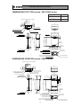
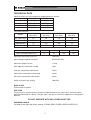
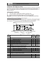
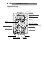
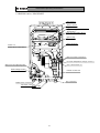
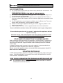
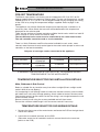
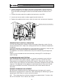
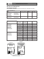
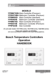
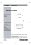
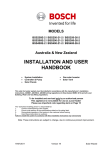
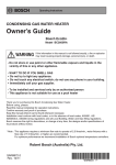
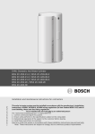
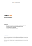
Invented for life
Installation/Operating Instructions
MODELS
Bosch 17e
Bosch 21e
Bosch 25e
Bosch 26e
(YS1770RA series, YS2170RA series, YS2670RABZ, YS2670RA series)
INSTALLATION MANUAL
This appliance must be installed in accordance with the manufacturer’s installation instructions, AS5601,
AS/NZS3500.4, AS3000 wiring regulations and all Local Building, Water and Gas fitting regulations.
To be installed and serviced only by an authorised person
This appliance is not suitable for use as a pool heater
The “authorised installing person” is responsible for :
1.
Correct commissioning of this appliance.
2.
Ensure unit performs to the specifications stated on the rating label.
3.
Demonstrate operation of unit to customer before leaving.
4.
Hand these instructions to customer.
Failure to install this appliance in accordance with these installation instructions may void warranty
SAR8512-7
Rev. 10/11
1
*SAR8512 C*
Invented for life
Installation/Operating Instructions
INDEX
Page Number
INTRODUCTION
3
DIMENSIONS
4
TECHNICAL DATA
5
APPLIANCE LOCATION
6
COMPONENT DETAILS
7
GAS CONNECTION
9
COLD WATER CONNECTION
9
HOT WATER CONNECTION
10
ELECTRICAL CONNECTION
10
PRE-SET TEMPERATURE
10
TEMPERATURE SELECTOR PAD INSTALLATION
11
TEMPERATURE SELECTOR PAD WIRING
11
TEMPERATURE CONTROL OPERATION
12
COMMISSIONING AND TESTING
12
TEMPERATURE SETTING
13
USER SAFETY INSTRUCTIONS
15
IN CASE OF DIFFICULTIES
15
Manufacturer’s Warranty
17
2
Invented for life
Installation/Operating Instructions
This Bosch water heater is an external, electronically controlled gas water heater.
This Bosch appliance is supplied set to operate without temperature selector pads
at a constant 55°C outlet temperature. To set the appliance to a different
temperature, refer to page 13 for details.
Available as optional extras are Main, Bathroom or Sub temperature selector pads.
Only one Main controller and one Bathroom controller can be
connected to the appliance along with up to 2 x Sub-controllers.
The bathroom and sub temperature selector pads have a maximum temperature
setting of 50°C for safety. To ensure compliance with Australian Standard AS/NZS
3500.4, in the bathroom area, this may be achieved by using a Bosch appliance
limited to 50°C or using a Bosch appliance with a delivery temperature greater than
50°C and installed with a tempering valve (high performance). In New Zealand,
please refer to the New Zealand Building Code and all other applicable electrical,
gas fitting and plumbing codes.
Before installing this appliance, carefully check that all packing materials have been
removed and that the appliance is correct for the gas supply to which it is to be
connected
3
Installation/Operating Instructions
Invented for life
DIMENSIONS YS1770RA series, YS2170RA series
L
YS2170RA series
214
57
40
178
338
97
40
( Perspective drawing from upper of appliance )
255
178
109
37
YS1770RA series
Gas connection R3/4
Outlet-water connection R3/4
Power cable intaking hole
350
120
334
170
11
510∼512
42
(PS flame installation pich)
520
487
542
120
60
Air-inlet
Bottom of case
Bottom of case
48
44
10
7-φ7.2 hole
Installation hole of wall
(Installed with two holes)
L
Flue terminal
10
50
10
25
85
31
7-φ7.2 hole
Installation hole of wall
(Installed with three holes)
10
84
133
Inlet-water connection
Water drain valve (Water filter)
49
Inlet-water connection R3/4
308∼320
(PS flame installation pich)
Gas connection
Outlet-water connection
Pressure relife valve and Water drain valve
Power cable intaking hole
Earth connection screw
DIMENSIONS YS2670RA series, YS2670RABZ
( Perspective drawing from upper of appliance )
47
40
37
338
97
40
268
178
109
Gas connection R3/4
Outlet-water connection R3/4
Power cable intaking hole
Inlet-water connection R3/4
350
120
85
170
334
11
25
42
(PS flame installation pich)
600
120
60
590∼592
567
622
253
Flue terminal
31
50
10
10
7-φ7.2 hole
Installation hole of wall
(Installed with three holes)
Air-inlet
Bottom of case
84
10
133
Inlet-water connection
Water drain valve (Water filter)
318∼320
49
7-φ7.2 hole
Installation hole of wall
(Installed with two holes)
48
44
10
Bottom of case
(PS flame installation pich)
Gas connection
Outlet-water connection
Pressure relife valve and Water drain valve
Earth connection screw
4
Power cable intaking hole
Installation/Operating Instructions
Invented for life
TECHNICAL DATA
Nominal hourly gas consumption by proportional gas control:
Natural Gas
LP Gas
17e
135 Mj/hr
135 Mj/hr
21e
25e
26e
170 Mj/hr
200 Mj/hr
200 Mj/hr
170 Mj/hr
200 Mj/hr
200 Mj/hr
Model
Natural Gas
Max (kPa)
Natural Gas
Min (kPa)
LP Gas
Max (kPa)
LP Gas
Min (kPa)
YS1770RA series
.67
.26
.78
.23
YS2170RA series
.69
.21
.91
.23
YS2670RABZ
.72
.19
.80
.22
YS2670RA series
.72
.19
.80
.22
Test Point Pressure:
Water heating capacity
17e
21e
25e
26e
Litres a minute raised 25°C
17
21
26
26
Maximum Inlet Water Pressure
1000 kPa
Input voltage single phase 50Hz
AC240/230 Volt
Maximum output current
1 Amp
AGA Approval certificate number
7032
Inlet gas connection male thread
20mm
Cold water connection male thread
20mm
Hot water connection male thread
20mm
Relief valve pressure setting
1600 kPa
DATA PLATE
Fitted inside of cabinet
GAS TYPE
The gas type is nominated on a temporary label located on the front cover, and on the data
plate located inside of cabinet. The gas type is the gas on which this appliance is designed to
operate.
DO NOT OPERATE WITH ANY OTHER GAS TYPE.
WARNING LABELS
Located on the right side of the cabinet- PLEASE READ THESE LABELS CAREFULLY!
5
Installation/Operating Instructions
Invented for life
POSITION FOR INSTALLATION
The heater must be installed by using a fixing method sufficient to hold the 21Kg weight
of unit (see the technical sheet for dimensions of mounting brackets and positions)
N.B.: On combustible surfaces e.g. weatherboards etc. it is not required to install a fire
proof back board.
APPLIANCE LOCATION
(1)
This water heater is approved for outdoor installation only.
(2)
Do not install this water heater with any modification or alteration.
(3)
Do not install this water heater indoors or in an enclosed space .
WARNING: FLUE OUTLET MUST BE FREE FROM ANY COMBUSTIBLE MATERIAL.
CLEARANCES FOR FLUE TERMINAL (front of heater)
The location of the flue terminal must comply with the clearances shown on this page. If
you are unsure about clearances not indicated here, in general refer to AS5601, or your
local authority. In Western Australia refer to the SECWA rules and regulations.
a
j
W
f
n
j
h
door
h
h
k
T
I
c
c
T
j
g
k
e
e
d
P
g
d
M
b
T
Use as a guide only. Refer to AS5601 or local gas fitting rules for specific locations
T=Flue terminal
I=Mechanical air inlet
Ref
M=Gas meter
P=Electricity meter
or fuse box
Item
Shaded area indicates
prohibited area
W=Window
Minimum
Natural
draft
a
b
c
d
e
f
g
h
j
k
n
Below eaves,balconies and other projections
Appliancesup to 50MJ/h input
300
Appliancesover 50 MJ/h input
500
From the ground, above a balcony or other surface
300
From a return wall or external corner
500
From a gas meter
1000
From an electricity meter or fuse box (P)
500
From a drain pipe or soil pipe
150
Horizontally from any building structure or obstruction facing a flue
500
terminal
From any other flue terminal, cowl, or combustion air intake
500
Horizontally from an opening window, door, non-mechanicalair inlet. Or other opening
into a building with the exception of sub floor ventilation
Appliancesup to 150 MJ/h
500
Appliancesover 150MJ/h input up to 200 MJ/h input
1500
Appliances over 200 MJ/h input up to 250 MJ/h input
1500
Appliances over 250 MJ/h input
1500
All fan assistedflue appliancesin the direction of discharge
From a mechanicalair inlet, including spa blower
1500
Vertically below an openable window, non-mechanicalair inlet, or any other opening into a
building with the exception of sub-floor ventilation:
Spaceheaters up to 50 MJ/h
150
Other appliancesup to 50 MJ/h
500
Appliancesover 50 MJ/h and up to 150 MJ/h input
1000
Appliancesover 150 MJ/h input
1500
6
Clearance
mm
Fan
assisted
200
300
300
300
1000
500
75
500
300
300
300
500
1500
1500
1000
150
500
1000
1500
Installation/Operating Instructions
Invented for life
COMPONENT DETAILS
• YS1770RA series, YS2170RA series
Flue terminal
Antifrost heater
High-limit switch
Empty heating prevention device
Thermal fuse
Over-heat prevention device
Ignition plug
Flame rod
Flame failure safety device
Burner manifold
Remote Control Connections
Hot-water temperature change connector
Water flow rate adjusting valve
Gas solenoid valve set
Earth leakage breaker
Printed circuit board
Outlet water connection
Gas connection
Inlet water connection
Power cable
7
Invented for life
Installation/Operating Instructions
• YS2670RA series, YS2670RABZ
Flue terminal
Antifrost heater
High-limit switch
Empty heating prevention device
Thermal fuse
Over-heat prevention device
Ignition plug
Burner manifold
Flame rod
Flame failure safety device
Remote
Controller
Remote Control Connections
Water flow rate adjusting valve
Hot-water temperature change connector
Gas solenoid valve set
Earth leakage breaker
Printed circuit board
Gas connection
Outlet water connection
Inlet water connection
Power cable
8
Invented for life
Installation/Operating Instructions
GAS CONNECTION
(1) Fit a union to the water heater gas inlet for easy connection and removal. The
thread diameter is 20 mm.
THIS DOES NOT INDICATE THE SIZE OF THE GAS SUPPLY.
(2) Fit an AGA / NZGA approved isolating gas cock in the supply line adjacent to
the water heater gas connection.
(3) Ensure that the supply pipe and the gas pressure regulator (LPG or Natural
Gas) has sufficient flow capacity for this and other appliances connected to the
fitting line.
(4) For LPG appliances ensure that gas cylinders are of sufficient size. The water
heater alone will require 2 x 45 Kg capacity cylinders.
(5) Before connecting the appliance to the gas service, purge any debris or air
from the gas service.
(6) Check all joints for leaks with an approved leak tester after connection.
Refer to AS 5601 Installation Code or NZ installation code for pipe sizing details.
Ensure that the gas pipe size is correct. If undersized the appliance will not
operate correctly
SERVICE CALLS ARE CHARGEABLE FOR UNITS WITH INCORRECT PIPE
SIZES OR BLOCKED GAS OR WATER FILTERS.
COLD WATER CONNECTION TO WATER HEATER
Refer to technical sheet for position of connections. The WATER INLET connection is
20 mm 3/4" BSP and requires a union to allow for removal of the water heater. Pipe
sizing from the cold water supply should be sized according to local BY LAWS for
water supply.
If sludge or foreign matter is present in the water supply it is recommended that a
separate filter/strainer be fitted to the cold water supply line.
Please ensure this appliance does not receive inlet water greater than 85°C
when used as a Solar booster.
ISOLATING GATE VALVE
A GATE VALVE OR BALL VALVE must be used on the cold water inlet to the water
heater. THIS REQUIREMENT IS AN AUSTRALIA WIDE REQUIREMENT UNDER
THE NATIONAL PLUMBING CODE.
STOP TAPS OR COMBINATION STOP TAPS AND NON-RETURN VALVES ARE
NOT TO BE USED.
N.B. NO PRESSURE REDUCTION VALVE IS REQUIRED UNLESS THE WATER
PRESSURE EXCEEDS 1000 kPa
9
Invented for life
Installation/Operating Instructions
HOT WATER CONNECTION TO WATER HEATER.
Refer to Technical Sheet for position of connection. The outlet connection is 20 mm (3/4"
BSP) MALE thread, and requires an isolating union to allow for removal of the unit.
Keep the pipe lengths to a minimum, and make sure that the pipework is well insulated as
correct performance of the appliance is dependent on properly insulated pipework.
DO NOT FIT ANY VALVES OR RESTRICTORS TO THE OUTLET OF THE WATER
HEATER.
DO NOT FIT ANY OBSTRUCTION TO THE PRESSURE RELIEF LOCATED ON THE HOT
WATER OUTLET CONNECTION.
After purging the air from the system using the hot water supply taps, remove the water
inlet strainer located on the cold water supply inlet connection. Remove any debris from
the filter and replace. When replacing the filter, do not over-tighten the “O” ring seal.
In order to comply with AS3498 the minimum distances as per the diagram below must be
observed.
These requirements are only for the 50°C locked units.
Closest hot water outlet
COLD
1/2" / 15mm 1.0m (min)
WARNING: For continued safety of this appliance it must be installed, operated and
maintained in accordance with the manufacture's instructions.
ELECTRICAL CONNECTION
The appliance is equipped with a 1.7 metre cable with a three pinned earthed plug
to be connected to a 240V, 50Hz supply. The electrical rating of the appliance is
0.4 Amps
The appliance requires a 240V in Australia and 230V in New Zealand, 50Hz
weatherproof plug installed in a protected position adjacent to the appliance.
IMPORTANT: The appliance should always be disconnected from the power
supply before any maintenance is carried out. If the power cord is damaged and
requires replacement, use only an original spare part available from the manufacturer.
10
Invented for life
Installation/Operating Instructions
PRE-SET TEMPERATURE
The Bosch water heaters are factory pre-set to operate at 55°C (or 50°C on 50
degree model) without temperature selector pads. The pre-set temperatures can be
altered to 60°C or 75°C, (or 42°C on 50 degree limited unit) by changing the setting
of the CPU or by using the temperature bridges supplied. Refer to page 13 for
details.
The appliance can also be fitted with temperature selector pads, available as an
accessory item. When fitted, the hot water will be delivered at the temperature
displayed on the selector pad.
There are two versions of remote controls available, the 66 series which has bath fill
alarm and the 67 series which has bath fill stop.
The two different series must never be connected to the same water heater.
The sub controller cannot be used as a sole controller.
There is a Main, Bathroom and Ensuite control available in each series, never
connect more than one of each control type to the water heater (except an extra sub
controller as the fourth controller.)
Only one of each type can be connected to the appliance.
67 series (Bathstop)
66 series (Bathfill)
Main controller
YPRM67XBN
YPRM67XB
YPRM66XB
Max temperature 75° C #
Bathroom controller
YPRS67XBN
YPRS67XB
YPRS66XB
Max temperature 50°C
Ensuite controller
YPRP62XB
YPRP62XB
Max temperature 50°C
# MAXIMUM TEMPERATURE IS CONTROLLED BY THE MAXIMUM DEFAULT
TEMPERATURE SET IN THE WATER HEATER
TEMPERATURE SELECTOR PAD INSTALLATION DETAILS
Main, Bathroom & Sub Control
Select a suitable flat, dry location away from direct sunlight.(Direct sunlight could
make it difficult to see display)
Cut an opening in wall through center of where the remote control is to be installed,
pull cable from wall cavity through opening. Attach cable to control. Remove cover
from remote control, locate control so that the wiring is not caught between the wall
and the remote control.
Secure control to wall using the screws provided and refit front cover.
Ensure that sufficient cable length is left to remove control if necessary.
TEMPERATURE SELECTOR PAD WIRING DETAILS
1 Remove the front cover of the water heater and locate the PCB on the right hand
side of the cabinet.
2 Locate the two control terminals on the PCB.
(Please be aware that all controller terminals connect back to the same two
points on the PCB)
11
Invented for life
Installation/Operating Instructions
3 Connect one end of the cable to the back of the controller using the terminal
points provided. Run the cable from each controller back to the hot water unit.
Push the cable up through the electrical cord hole located at the base of the
unit.
4 Connect the other end of the cable to the terminals on the PCB.
5 Locate and secure cable to cable support bracket inside unit.
6 Replace the appliance front cover, attach the earth wire and connect the power
Remote Control Connections
TEMPERATURE CONTROL OPERATION
Turn the main temperature selector ON by pressing the Operation switch ON, the
control will display 40°C. Adjust the setting control switch if a different temperature
is required.
To transfer operation to the bathroom or sub control press the priority switch on the
bathroom or sub control and adjust the temperature as required.
The appliance can also be switched on at any of the selectors by pressing the on
button
Priority can be cancelled at the main control by switching OFF & ON (Except if
water running)
COMMISSIONING AND TESTING
After completing the installation of the unit, connect manometer to gas inlet test
point, turn on the water, power and gas supplies to the unit. Confirm the water
heater delivers the temperature the consumer requires. With the hot water running,
confirm correct gas inlet pressure and remove manometer. Retighten test point and
soap test. Test operation of the appliance, explain operation to consumer & hand
over these installation instructions. Please leave your contact details with the
consumer.
BURNER PRESSURE ADJUSTMENT
No adjustment should be necessary providing the gas inlet pressure is correct.
Burner pressure adjustment is necessary when converting to a different gas type or
replacing the PCB. Refer to service manual for details.
N.B. The combustion fan continues to operate for approximately 7 minutes after
the unit is turned off. This is normal, not a fault.
12
Installation/Operating Instructions
Invented for life
SETTING THE TEMPERATURE
USE BRIDGES PROVIDED
Use the bridges provided to change the temperature as indicated in the table….
Remote controller less
Unit
Factory Setting
Bridge A
Bridge B
YS1770RA
YS1770RAH
YS2170RA
YS2170RAH
YS2670RA
YS2670RAH
YS2670RABZ
55°C
75°C
60°C
YS1770RA5
YS2170RA5
YS2670RA5
YS2670RA5P
50°C
50°C
42°C
Connected remote controller
Unit
Remote
controller
Factory
Setting
Bridge A
Bridge B
YPRM66XB
37-55°C
37-75°C
37-60°C
YPRS66XB
37-50°C
37-50°C
37-50°C
YPRM67XBN
37-55°C
37-75°C
37-60°C
YPRS67XBN
37-50°C
37-50°C
37-50°C
YPRM67XB
37-55°C
37-75°C
37-60°C
YPRS67XB
37-50°C
37-50°C
37-50°C
YPRP62XB
37-50°C
37-50°C
37-50°C
YPRM66XB
37-50°C
37-50°C
37-42°C
YPRS66XB
37-50°C
37-50°C
37-42°C
YPRM67XBN
37-50°C
37-50°C
37-42°C
YPRS67XBN
37-50°C
37-50°C
37-42°C
YPRM67XB
37-50°C
37-50°C
37-42°C
YPRS67XB
37-50°C
37-50°C
37-42°C
YPRP62XB
37-50°C
37-50°C
Step 1 : Locate bridges attached to the inside of the front cover
37-42°C
YS1770RA
YS1770RAH
YS2170RA
YS2170RAH
YS2670RA
YS2670RAH
YS2670RABZ
YS1770RA5
YS2170RA5
YS2670RA5
YS2670RA5P
YS2670RA series
YS2670RABZ
YS1770RA series
YS2170RA series
A
B
A
B
Into Bridge A and Bridge B
13
Installation/Operating Instructions
Invented for life
Step 2: Turn off power to unit.
Setting
Modulation
B
Adjust
Switch
A
Remote
Controller
Step 3: Insert bridge into plastic clip between the controller terminals
PCB
Step 4: Turn power back on
Unit is now set as per the table on the previous page.
14
Invented for life
Installation/Operating Instructions
USER SAFETY INSTRUCTIONS
PLEASE CAREFULLY READ THIS USER INSTRUCTION BEFORE USE.
You have selected the Bosch Electronic computer controlled hot water unit. The
following instructions will assist you to obtain the best performance from your Bosch
water heater
SAFETY
1.
Always check water temperature by hand before entering the
shower or bath. The temperature may have been changed.
2.
Do not touch cover or flue outlet when the Bosch water heater is
in operation.
3.
Keep flammable materials, trees, shrubs etc. away from the
Bosch water heater
4.
Water flow needs to be more than 2.0L/min. to operate these
Bosch Water Heaters. Hot water temperature may vary at low
water flows, or the Water Heater may go out without warning.
5
Warning - If the appliance does not operate, burns with yellow
flame, leaks water or a gas smell is evident, turn off and contact
the local gas authority, the manufacturer or an authorized
service person.
6
In cases where the inlet water temperature is greater than
20°C the flow rate will need to be increased to maintain low
temperatures if using a temperature controller.
IN CASE OF DIFFICULTIES
If the Bosch water heater ceases to operate, please check that the electricity supply
is available. (Check for display of temperature at control pad or plug in a portable
appliance.) Also check that the gas supply is turned on.
If a fault develops there are no user adjustments or serviceable components
contained in this appliance. Please contact an authorized service person.
SERVICING AND MAINTENANCE
These gas water systems should be serviced at intervals not exceeding two years
in domestic applications and in commercial applications intervals not exceeding
one year.
For information on how to locate service and parts please phone 1300 30 70 37.
15
WATER QUALITY
All Bosch water heating appliances are constructed from high quality materials and
components and all are certified for compliance with relevant parts of Australian and
New Zealand gas, electrical and water standards.
Whilst Bosch water heaters are warranted against defects, the warranty is conditional
upon correct installation and use, in accordance with detailed instructions provided
with the heater. In the case of the water supplied to the heater, it is important that the
water quality be of acceptable standard.
The water quality limits/parameters listed in water quality table are considered
acceptable and generally, Australian and New Zealand suburban water supplies fall
within these limits/parameters.
In areas of Australia and New Zealand where water may be supplied, either fully or
partly, from bores, artesian wells or similar, one or more of the important limits may well
be exceeded and the heater could, therefore, be at risk of failure.
Where uncertainty exists concerning water quality, intending appliance users should
seek a water analysis from the water supplying authority and in cases where it is
established that the water supply does not meet the quality requirements of the water
quality table, the Bosch warranty would not apply.
WATER QUALITY TABLE
Maximum levels
pH
Saturation
Total
Hardness
Chlorides
Sodium
Iron
200mg/l
250mg/l
180mg/l
1mg/l
Index(LSI)
(langelier)
6.5-9
+0.4 to
Minus 1.0
@65C
16
Robert Bosch (Australia) Pty Ltd (Bosch)
Manufacturer’s Warranty
(Applicable for purchases from 1 January 2012)
All Bosch hot water units are carefully checked, tested and subject to stringent quality controls.
1. Warranty
Bosch offers, at its option, to repair or exchange this Bosch hot water unit or the relevant part
listed in clause 2 below at no charge, if it becomes faulty or defective in manufacture or materials
during the warranty period also stated in clause 2. This warranty is offered in addition to any
other rights or remedies held by a consumer at law.
2. Warranty periods & coverage
(a) Domestic applications: 3 years (parts and labour)
(b) Heat exchangers used in domestic applications: 10 years (parts only)
(c) Commercial applications: 12 months (parts and labour)
(d) Heat exchangers used in commercial applications: 5 years (part only)
All warranty periods commence on the date of purchase of the hot water unit by the end-user.
However, where the date of purchase by the end-user is more than 24 months after the date of
manufacture, all warranty periods will automatically commence 24 months after the date of
manufacture.
3. Warranty exclusions
This warranty is VOID if any damage to or failure of the hot water unit is caused wholly or partly
by:
(a) faulty installation
(b) neglect, misuse, accidental or non-accidental damage, failure to follow instructions
(c) use of the unit for purposes other than which it was designed or approved
(d) unauthorised repairs or alterations to the unit without Bosch’s consent
(e) use of unauthorised parts and accessories without Bosch’s consent
(f) use of non-potable water or bore water in the hot water unit (see product instructions for
further details)
(g) continued use after a fault becomes known or apparent.
This warranty DOES NOT include:
(a) costs of consumables or accessories
(b) wear and tear, normal or scheduled maintenance
(c) to the extent permitted by law, any damage to property, personal injury, direct or indirect loss,
consequential losses or other expenses
(d) changes in the condition or operational qualities of the hot water unit due to incorrect storage
or mounting or due to climatic, environmental or other influences.
NOTE: Any service call costs incurred by the owner or user of the hot water unit for any matter
not covered by the terms of this warranty will not be reimbursed by Bosch, even if those costs are
incurred during the warranty period. If the hot water unit is located outside the usual operating
area of a Bosch service agent, the agent’s travel, freight or similar costs are not covered by this
warranty and must be paid by the owner or user of the hot water unit.
4. Warranty conditions
(a) Proof of purchase may be required.
(b) The hot water unit must be installed by an authorised and licensed installer.
(c) Proof may be required of the date of installation and correct commissioning of the hot water
unit has been carried out to Bosch’s satisfaction (such as a certificate of compliance).
17
(d) Repair or replacement of the hot water unit or any parts under this warranty does not
lengthen or renew the warranty period.
(e) This warranty is not transferable and is only offered to the original purchaser of the hot water
unit.
(f) No employee or agent of Bosch is authorised to amend the terms of this warranty.
(g) This warranty only applies to Bosch hot water units purchased from an authorised reseller and
installed in Australia or New Zealand.
(h) To the extent that any condition or warranty implied by law is excludable, such condition or
warranty is excluded.
5. How to lodge a warranty claim and warranty procedure
(a) Warranty claims must be made with the Bosch Customer Contact Centre (Australia: ph 1300
307 037; New Zealand: ph 0800 543 352). Please be ready to provide the model and serial
numbers, date of installation, purchase details and a full description of the problem. Warranty
claims must be made before the end of the warranty period.
(b) All warranty service calls must conducted by an authorised Bosch service agent.
(c) Invoices for attendance and repair of a hot water unit by third parties not authorised by Bosch
will not be accepted for payment by Bosch.
6. Privacy Act 1988 (Cth)
A customer's personal information collected during warranty claims may be used for the provision
of customer support, for the provision of information about products and services and for other
marketing activities undertaken by Bosch and its Bosch Service Agents who are authorised to
carry out warranty repairs on behalf of Bosch (Purpose). Bosch is committed to protecting the
privacy of its customers' personal information. It will act in compliance with the National Privacy
Principles and Privacy Act 1988 (Cth). Bosch will not forward customers' personal information to
third parties other than for the Purpose. A customer can object at any time to the use of their
personal information for the Purpose. Bosch will cease to use a customer's personal
information accordingly if an objection is made.
7. Bosch contact details
If you have any questions about this warranty or to lodge a warranty claim, please contact:
Robert Bosch (Australia) Pty Ltd
1555 Centre Road, Clayton, Victoria 3168
Tel: Australia: 1300 307 037
Tel: New Zealand: 0800 543 352
IMPORTANT NOTE FOR AUSTRALIAN CONSUMERS
Our goods come with guarantees that cannot be excluded under the Australian Consumer Law.
You are entitled to a replacement or refund for a major failure and for compensation for any other
reasonably foreseeable loss or damage. You are also entitled to have the goods repaired or
replaced if the goods fail to be of acceptable quality and the failure does not amount to a major
failure.
18