1
SSCNETIII Compatible
MOTION CONTROLLER Q series
Taking motion control to the age of optics
Mitsubishi Electric Corporation Nagoya Works is a factory certified for ISO14001
(standards for environmental management systems) and ISO9001(standards for
quality assurance management systems)
EC97J1113
Taking Motion Control to Higher
Performance Standards by Incorporating
Optics!
Taking motion control to new ranges with
the high-speed synchronous network SSCNETIII!
compatible
Introducing the SSCNETIII compatible Q173HCPU/Q172HCPU to the Motion controller Q Series!
High speeds and high accuracies are attained to comply with the MELSERVO-J3 servo amplifier.
The conventional Q Series Motion controller’s functions and programming environment are incorporated.
(Note) • Q173HCPU/Q172HCPU can be connected only to the SSCNETIII compatible MR-J3-B.
• SSCNET(Servo System Controller NETwork)
-
Attain High Speeds and High Accuracies with Motion Control
■ Operation tact time is shortened with a motion operation cycle of min. 0.44ms (2 times the conventional cycle).
■ Accuracy for the synchronous and speed/position control is improved by reducing the command communication cycle to the servo
amplifier to min. 0.44ms (2 times the conventional cycle).
■ Motion CPU module contains a 64-bit RISC processor for motion control and event processing.
Large volumes of data can be communicated with a personal computer without affecting motion control performance.
■ Compatible with the high-speed sequence processing of the MELSEC-Q Series PLC CPU (Platform).
(Basic command scan time of 34ns using the Q25HCPU)
■ Various motion functions are included, such as multi-axis interpolation functions, speed control, electronic cam profiles and locus
control.
■ Control with suppressed variation in response time is realized using the Motion SFC programming method as a flowchart.
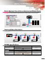
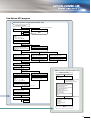
Multiple CPU System with the Q Series PLC (Platform)
■ The power supply module, base unit, and I/O modules of the MELSEC-Q Series PLC can be shared.
■ Control processing is distributed to each CPU module among the Multiple CPU system, and it also corresponds to the intelligent
control system.
■ Personal computer technology is utilized using a PC (Personal Computer) CPU module.
✽ A personal computer CPU is the product of CONTEC, Ltd.
Sequence
control
processor
Common memory
Motion
control
processor
Q Series PLC
High-Speed System Bus
Sensor, solenoid, etc.
(DI/O)
Motion control dedicated I/F
(DOG signal, pulse generator)
PLC intelligent function module
(A/D, D/A, etc.)
1
SSCNET#
Servo amplifier
Common memory
Motion CPU
Device memory
Servo amplifier
Q Series PLC CPU
Device memory
Servo
motor
Servo
motor
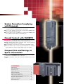
System Formation Complying
with Demands
■ Individual CPU modules for PLC control and motion control allow for the
economical selection of optimized CPU’s for the system.
■ Up to 4 CPU modules can be freely selected in the Multiple CPU
system. (1 PLC CPU must be used.)
■ Up to 96 axes can be controlled per 1 system in the Multiple CPU
system. (When using 3 modules of Q173HCPU(-T).)
Overall Control with SSCNET#
■ A synchronous and absolute system for the servomotor can be easily
composed using the high-speed serial communication method.
■ Simple wiring by quick release connection using connectors between
the Motion controller and servo amplifiers.
■ Servo amplifiers for up to 32 axes can be batch controlled with 1 CPU.
■ Motor information such as torque, speed, and position can be batch
monitored with the controller using the digital oscilloscope function.
Compact Size and Savings in
Space of Controller
■ The controller’s miniaturization is realized by using the same hardware
architecture as the MELSEC-Q Series PLC CPU.
■ Additional savings in space and cost may be realized using a 12-slot
base.
CONTENTS
Main Features ........................................................... 1
System Configuration ................................................ 7
Product Line-up ........................................................ 9
Multiple CPU System .............................................. 11
Motion SFC Program .............................................. 13
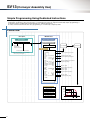
SV13 (Conveyor Assembly Use) ................................. 21
SV22 (Automatic Machinery Use) ................................ 25
Integrated Start-Up Support Software MT Developer ..... 29
Overview of CPU Performance ............................... 31
Equipment Configuration ........................................ 33
Exterior Dimensions ................................................ 39
2
Powered Up Motion Control
■ Security function to protect user’s know-how incorporated
–A function to protect user programs with a password has been added.
■ Integration with MR Configurator
■ Suitable for devices, such as spinners, with the speed control function with fixed position stop
(Orientation function)
■ Improved synchronization accuracy between multiple axes
–Errors caused by synchronous encoder’s processing time or servo’s droop pulses is automatically compensated with the phase
compensation function.
■ 262,144 pulse synchronous encoder (18-bit) is available
–The synchronous operation accuracy at low speeds is tremendously improved (16-fold compared to conventional model).
■ Synchronous control and PTP positioning are simultaneously controlled
–Mixed function of virtual mode with real mode.
■ Smoothing clutch linear acceleration/deceleration function
Speed Control Function with Fixed Position Stop (Orientation Function)
The servomotor can be rotated at preset speed and then stopped at preset position after the fixed position stop command ON.
Not only the speed but also acceleration/deceleration time can be changed to an optional value while operating.
Value changed with speed change
request command
v
a
b
c
d
t
Fixed position stop acceleration/deceleration time
Rotates at a fixed speed
ON
Servo program start
OFF
Speed change request
command
OFF
Fixed position stop command
OFF
ON
Stop at preset position
ON
Servomotor
Fixed position stop acceleration
/deceleration time
(Indirect setting device)
a
b
c
d
Phase Compensation Function
When carrying out tracking synchronization with the synchronous encoder, delays in the processes, etc., cause the phase to
deviate at servomotor shaft end in respect to the synchronous encoder. The phase compensation function compensates in this
case so that the phase does not deviate. The phase deviation between the synchronous encoder and cam angle can be
eliminated by using this for the electronic cam.
Example of use with electronic cam
Operate a cutter with the electronic
cam in synchronization with the
conveyor speed
Angle
Servomotor
Synchronous encoder angle
Cam angle
Time
Phase deviates between synchronous encoder
and electronic cam.
P1
Phase compensation
Angle
Synchronous encoder angle
Synchronous encoder
1-axis
Cam angle
Electronic cam
(Servomotor)
3
Mechanical system
program
Time
Phase deviation is eliminated, and phases are
completely synchronized.
Mixed Function of Virtual Mode with Real Mode
The positioning control can be executed for the axis set to the real mode axis at the mechanical system editor monitor in the virtual
mode.
Real mode
[K10 : Real]
1 INC-2
Axis
3,
10000PLS
Axis
4,
20000PLS
Combined-speed 30000PLS/s
V.1
Virtual servomotor
Axis4
20000
1-axis
2-axis
Electronic cam
(Servomotor)
Servomotor
start
Roller
(Servomotor)
10000
Mechanical system
program
10000
20000
Axis3
Smoothing Clutch Linear Acceleration/Deceleration Function
The linear acceleration/deceleration system can be selected in the smoothing clutch.
<State of clutch operation>
V.1
<Input to clutch>
V
Virtual servomotor
t
Clutch ON
Clutch OFF
1-axis
Rotary table
(Servomotor)
Mechanical
system
program
<System of
processing>
<Output to output axis>
V
Acceleration by smoothing processing
Time constant
system
A
B
Deceleration by
smoothing processing
t
t*
Time constant system
* : Smoothing time constant
Slippage system
(Exponential function system,
Linear acceleration/
deceleration system)
A
Time until it becomes t=––– ✕100=63[%]
B
V
Acceleration by smoothing processing
Slippage system
(Exponential function
system)
Slippage
Deceleration by
smoothing processing
t
V
Acceleration by smoothing processing
Slippage system
(Linear acceleration/
deceleration system)
Slippage
Deceleration by
smoothing processing
t
4
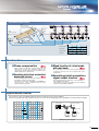
The High-Speed Synchronous Network SSCNET
Reduced cable
Reduced wiring
preparation and
wiring man-hours
Unified parameter
Easy axis addition
control
Comprehensive · Multi-axis parameter control
development · Multi-axis monitor
environment
· Multi-axis graph
Command synchronization system
Data communication
Absolute value system
High-speed
Improved synchronization
communication
accuracy
Super high-resolution encoder
Large capacity data
communication
Noise resistance
Long-distance wiring
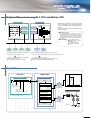
Attain 50Mbps High-speed Communication
with Optical Communication
Improved system responsiveness
Network communication speed
The speed of exchanging data between the controller and servo
amplifier has been greatly increased thereby shortening the cycle
time.
5.6
A173UHCPU/
Q173CPUN
Speed increased
by approx. 10-fold
50
Q173HCPU
Enhanced communication reliability
0
10
20
30
The optical fiber cable was adopted.
40
50
Baud rate [Mbps]
Overall cable length
Improved freedom to device layout
This model is compatible with long-distance wiring (Maximum
overall distance: up to 50[m] (164.04[ft.] ) between stations (Note) ×
number of axes).
30
A173UHCPU/
Q173CPUN
Compatible with an approx.
25-fold long distance
800
(Note)
Q173HCPU
(Note): When using long distance cable: 50[m] (164.04[ft.] ) between stations × 16 axes = 800[m]
(2624.67[ft.] )
0
Wiring is reduced by issuing the stroke limit signal and proximity
dog signal via the servo amplifier.
200
(656.17)
400
(1312.34)
Machine wiring for SSCNETIII
600
800
(1968.50) (2624.67)
Distance [m(ft.) ]
Controller panel
Up to 50[m] (164.04[ft.] )
between stations(Note)
MODE
RUN
ERR
USER
BAT
BOOT
POWER
SSCNETIII cable
PULL
PULL
MODE
RUN
ERR
USER
BAT
BOOT
PULL
USB
USB
RS-232
MR-J3-B
Enlarged view
Amplifier panel
Machine
(Note): When using long distance cable
Amplifier panel
Machine
Amplifier panel
Machine
FLS
DOG
RLS
Servo external signal (FLS, RLS, DOG)
The wire length can
be shortened
High Speed and Accuracy with Synergic Effect with MR-J3
Combined with MR-J3, SSCNET# realizes faster and smoother operations for higher speed
(HF-KP maximum motor speed: 6000r/min) and higher accuracy (HF-KP motor resolution: 262144PLS/rev).
5
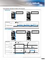
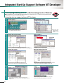
Shorter Adjustment Time with Servo Adjustment and Multiple Monitor
Communication between the MR Configurator (setup software) and servo amplifier via Motion controller is possible. Multiple
servo amplifiers can be adjusted just by connecting between the personal computer and Motion controller with a cable.
Q173HCPU/Q172HCPU
MODE
RUN
ERR
USER
BAT
BOOT
POWER
Click on
the icon!
PULL
PULL
MODE
RUN
ERR
USER
BAT
BOOT
PULL
USB
USB
RS-232
Start MR Configurator from the MT Developer
Cables do not need to be reconnected
Select the required number of axes
and display as a list.
MR-J3-B
MR Configurator
Data write
Data read
Improved Noise Resistance
The optical fiber cables used for SSCNET# dramatically improve the resistance against noise which enters from the power cable
or external devices.
MODE
RUN
ERR
USER
BAT
BOOT
POWER
Guards
against Noise
MODE
RUN
ERR
USER
BAT
BOOT
Guards
against Noise
Guards
against Noise
Noise
Noise
SSCNET#
PULL
PULL
USB
PULL
USB
RS-232
Noise
SSCNET Specifications
Item
SSCNET#
SSCNET
Optical Fiber Cable
Communication Medium
Communication Speed
Communication
Cycle(Note-2)
Send
Receive
Maximum Control Axes per System
Transmission Distance
Metal Cable
Standard Cord for Inside Panel
Standard Cable for Outside Panel
Long-Distance Cable(Note-1)
50Mbps
5.6Mbps
0.44ms/0.88ms
0.88ms/1.77ms/3.55ms
0.44ms/0.88ms
3.55ms
Communication Cycle 0.44ms : 8 axes/system
Communication Cycle 0.88ms : 16 axes/system
8 axes/system
Maximum 20m between Stations
Maximum Overall Distance 320m
(20m ✕ 16 axes)
Maximum 50m between Stations
Maximum Overall Distance 800m
(50m ✕ 16 axes)
Overall Distance 30m
Noise Resistance
(Note-1) : Special-order product.
(Note-2) : Communication cycle differs according to the setting of operation cycle.
6
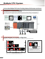
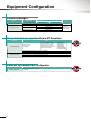
System Configuration
Flexible High-Speed Motion Control System Achieved with Multiple CPU
■ Compatible with the Q Series PLC (Platform) in the Multiple CPU system.
■ The appropriate CPU modules for PLC control and Motion control can be selected to meet the application requirements.
■ The Multiple CPU configuration allows up to 4 CPU modules to be selected. (1 PLC CPU must be used.)
■ Up to 96 axes of servomotors per system can be controlled by using 3 modules of Q173HCPU(-T).
■ Each unit installed in the CPU base and the extension base is controlled by control CPU specified by the parameter.
PLC CPU (Note-1)/Motion CPU
(Up to 4 modules)
Q6ⵧP-ⵧⵧ
For Motion CPU
Qⵧⵧ (H) CPU
Q17ⵧHCPU(-T)
Q172LX
For PLC CPU
SSC I/F card
A30CD-PCF
SSCNET (Note-4)
PLC programming
software
GX Developer Ver.6 or later
(CD-ROM)
SWⵧD5C-GPPW-E
USB (Note-5)
Laptop personal computer
(WinNT/Win98/Win2000/WinXP)
Integrated start-up support
environment
CPU base Q3ⵧB
Servo set up
Integrated start-up
software
support software
MR Configurator
MT Developer
(CD-ROM)
Ver.00K or later
MRZJW3-SETUP221E
(CD-ROM)
SW6RNC-GSVPROE
USB (Note-5)/RS-232
Teaching
unit (Note-8)
A31TU-DⵧK13
SSC I/F board
Aⵧ0BD-PCF
SSCNET (Note-4)
SSCNET#
(1 system)
USB (Note-5)
Desktop personal computer
(WinNT/Win98/Win2000/WinXP)
Integrated start-up support environment
Extension cable QC
Peripheral device
configuration
SSCNET#
(2 systems)
B
Motion CPU/
PLC CPU
control module
Graphic operation
terminal (GOT)
7
Extension base (Note-6)
(Up to 7 stages)
Q6ⵧB
III
■Operating system software packages
Operating system
software
(FD)
SW6RN-SVⵧⵧQⵧ
Conveyor assembly use
Automatic machinery use
Motion SFC compatible
Motion SFC compatible
Dedicated language
Mechanical support
language
[Applications]
Electronic component assembly, Inserter,
Feeder, Molder, Conveying equipment, Paint
applicator, Chip mounting, Wafer slicer,
Loader/Unloader, Bonding machine, X-Y table
Linear interpolation (1 to 4 axes), Circular interpolation, Constant-speed,
Fixed-pitch feed, Speed control with fixed position stop, Speed switching,
Speed control, Speed/position switching, Teaching
Motion CPU control (Note-2)
modules
Q172EX-S2
Q173PX
QI60
PLC CPU control (Note-3)
modules
QX/Yⵧⵧ
[Applications]
Press feeder, Food processing, Food packaging,
Winding machine, Spinning machine, Textile
machine, Printing machine, Book binder, Tire
molder, Paper-making machine
Synchronous control, Electronic shaft, Electronic clutch, Electronic cam,
Draw control
Notes : 1. PLC CPU for Multiple CPU can be used in Q-mode.
2. Only input module among Motion CPU control modules can be accessed from
PLC CPU.
3. Other CPU modules cannot be accessed from Motion CPU.
4. Only 1 PC can be connected via SSCNET.
5. USB cannot be used in WindowsNT® 4.0.
6. Motion CPU cannot control the module installed to the QA1S6ⵧB.
7. The external battery for backup of parameter/program is required at the time of
continuous power failure for 1000 hours or more. (Q6BAT is not supplied with
Q170HBATC).
8. In planning stages. When using the teaching unit A31TU-DⵧK13, please use
Motion CPU for teaching unit.
9. Connecting target can be selected for each axis from general-purpose input of
servo amplifier or Q172LX.
Device configuration
Motion CPU input/output
(Up to 256 points)
External interrupt input
(16 points)
Manual pulse generator (3 units per module)
MR-HDP01
Battery holder unit
Q170HBATC (Note-7)
(Q6BAT has been installed)
Serial absolute synchronous encoder
(2 units per module)
Q170ENC
Servo external signal (Note-9)
(FLS, RLS, STOP, DOG/CHANGE) ✕ 8 axes
Servo amplifier MR-J3-ⵧB
Servo amplifier MR-J3-ⵧB
Servomotor
Servomotor
Q173HCPU(-T): 2 systems
(Up to 32 axes)
Q172HCPU(-T): 1 system
(Up to 8 axes)
Servo external signal (Note-9)
(FLS, RLS, DOG)
8
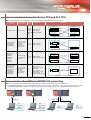
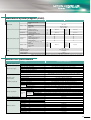
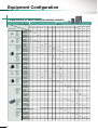
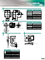
Product-Line-up
Motion CPU module
Q173HCPU
Q173HCPU-T
(Up to 32 axes control)
Specifications
Items
Q173HCPU
Q173HCPU-T
Number of control axes
Up to 32 axes
0.44ms : 1 to 3 axes
0.88ms : 4 to 10 axes
SV13
1.77ms : 11 to 20 axes
3.55ms : 21 to 32 axes
Operation cycle
(default)
0.88ms : 1 to 5 axes
1.77ms : 6 to 14 axes
SV22
3.55ms : 15 to 28 axes
7.11ms : 29 to 32 axes
Servo amplifiers are connected via SSCNET# (2 systems)
Servo amplifier
USB/SSCNET
Peripheral I/F
None
Provided (SV13 use)
Teaching operation function
Manual pulse generator operation function Possible to connect 3 modules
Synchronous encoder operation function Possible to connect 12 modules (Note-1) (SV22 use)
Up to 4 modules per CPU
Q172LX
Up to 6 modules per CPU (SV22 use)
Q172EX-S2
Up to 4 modules per CPU (Incremental synchronous encoder use in SV22)
Q173PX
Up to 1 module per CPU (Only manual pulse generator use)
QX
Controllable QY
modules
QH
QX Y
Total : Up to 256 points per CPU
Q64AD/Q68ADV/Q68ADI/
Q62DA/Q64DA/Q68DAV/
Q68DAI
QI60
PLC extensions
5VDC current consumption [A]
Mass [kg]
Exterior dimensions [mm(inch)]
Up to 1 module per CPU
Up to 7 base units
1.25
1.56 (Note-2)
0.23
0.24
H 104.6(4.11) ✕ W 27.4(1.08) ✕ D 114.3(4.50)
(Note-1) : Up to 12 modules can be used in the sum total with the manual pulse generator.
(Note-2) : Current consumption 0.26 [A] of the teaching unit is included.
Motion CPU module
Q172HCPU
Q172HCPU-T
(Up to 8 axes control)
Specifications
Items
Q172HCPU
Operation cycle
(default)
SV13
0.44ms : 1 to 3 axes
0.88ms : 4 to 8 axes
SV22
0.88ms : 1 to 5 axes
1.77ms : 6 to 8 axes
Servo amplifier
Peripheral I/F
Teaching operation function
Manual pulse generator operation function
Synchronous encoder operation function
Q172LX
Q172EX-S2
Q173PX
QX
Controllable
QY
modules
QH
QX Y
Q64AD/Q68ADV/Q68ADI/
Q62DA/Q64DA/Q68DAV/
Q68DAI
QI60
PLC extensions
5VDC current consumption [A]
Mass [kg]
Exterior dimensions [mm(inch)]
Servo amplifiers are connected via SSCNET# (1 system)
USB/SSCNET
None
Provided (SV13 use)
Possible to connect 3 modules
Possible to connect 8 modules (Note-1) (SV22 use)
Up to 1 module per CPU
Up to 4 modules per CPU (SV22 use)
Up to 3 modules per CPU (Incremental synchronous encoder use in SV22)
Up to 1 module per CPU (Only manual pulse generator use)
Total : Up to 256 points per CPU
Up to 1 module per CPU
Up to 7 base units
1.14
1.45 (Note-2)
0.22
0.23
H104.6(4.11) ✕ W27.4(1.08) ✕ D114.3(4.50)
(Note-1) : Up to 8 modules can be used in the sum total with the manual pulse generator.
(Note-2) : Current consumption 0.26 [A] of the teaching unit is included.
9
Q172HCPU-T
Up to 8 axes
Number of control axes
III
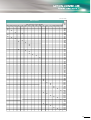
Servo external signals interface module
Q172LX
Items
Upper stroke
limit input,
Lower stroke
limit input,
Stop signal input,
Proximity dog/
speed-position
switching input
Number of input points
Input method
Rated input voltage/current
Operating voltage range
ON voltage/current
OFF voltage/current
Upper/lower
stroke limit and
Response STOP signal
time
Proximity dog/
speed-position
switching signal
Number of I/O occupying points
5VDC current consumption [A]
Mass [kg]
Exterior dimensions [mm(inch)]
Specifications
Servo external control signals : 32 points, 8 axes
Sink/Source type (Photocoupler)
12VDC 2mA, 24VDC 4mA
10.2 to 26.4VDC (Ripple ratio 5% or less)
10VDC or more/2.0mA or more
1.8VDC or less/0.18mA or less
1ms (OFF → ON, ON → OFF)
0.4ms/0.6ms/1ms (OFF → ON, ON → OFF)
✽ CPU parameter setting, default 0.4ms
32 points (I/O allocation: Intelligent, 32 points)
0.05
0.15
H98(3.86) ✕ W27.4(1.08) ✕ D90(3.54)
Synchronous encoder interface module
Q172EX-S2
Items
Serial absolute
synchronous
encoder input
Tracking enable
input
Number of modules
Applicable encoder
Position detection method
Transmission method
Back up battery
Maximum cable length
Number of input points
Input method
Rated input voltage/current
Operating voltage range
ON voltage/current
OFF voltage/current
Response time
Number of I/O occupying points
5VDC current consumption [A]
Mass [kg]
Exterior dimensions [mm(inch)]
Specifications
2 per module
Q170ENC
Absolute (ABS) data method
Serial communications (2.5Mbps)
A6BAT/MR-BAT
50m
2 points
Sink/Source type (Photocoupler)
12VDC 2mA, 24VDC 4mA
10.2 to 26.4VDC (Ripple ratio 5% or less)
10VDC or more/2.0mA or more
1.8VDC or less/0.18mA or less
0.4ms/0.6ms/1ms (OFF → ON, ON → OFF)
✽ CPU parameter setting, default 0.4ms
32 points (I/O allocation: Intelligent, 32 points)
0.07
0.15
H98(3.86) ✕ W27.4(1.08) ✕ D90(3.54)
Manual pulse generator interface module
Q173PX
Items
Manual pulse
generator/
incremental
synchronous
encoder input
Tracking enable
input
Number of modules
High-voltage
Voltage-output/
Open-collector type Low-voltage
Differential-output High-voltage
type
Low-voltage
Input frequency
Applicable types
Specifications
3 per module
3.0 to 5.25VDC
0 to 1.0VDC
2.0 to 5.25VDC
0 to 0.8VDC
Up to 200kpps (After magnification by 4)
Voltage-output/Open-collector type (5VDC),
(Recommended product: MR-HDP01)
Differential-output type (26LS31 or equivalent)
Maximum cable length
Voltage-output/Open-collector type: 10m(32.79ft.)
Differential-output type: 30m(98.36ft.)
Number of input points
Input method
Rated input voltage/current
Operating voltage range
ON voltage/current
OFF voltage/current
3 points
Sink/Source type (Photocoupler)
12VDC 2mA, 24VDC 4mA
10.2 to 26.4VDC (Ripple ratio 5% or less)
10VDC or more/2.0mA or more
1.8VDC or less/0.18mA or less
Response time
0.4ms/0.6ms/1ms (OFF → ON, ON → OFF)
✽ CPU parameter setting, default 0.4ms
Number of I/O occupying points
5VDC current consumption [A]
Mass [kg]
Exterior dimensions [mm(inch)]
32 points (I/O allocation: Intelligent, 32 points)
0.11
0.15
H98(3.86) ✕ W27.4(1.08) ✕ D90(3.54)
10
Multiple CPU System
An Innovative Multiple CPU System Providing Advanced Performance and Control
Distribution of control processing
■ By distributing such tasks as machine control, communication control, servo control, and information control among multiple
processors, CPU load is dramatically reduced, allowing extremely fast and efficient processing of complex applications.
■ Various I/O modules are assigned to their respective CPU module and can be used on the same base unit simultaneously.
Host computer
PLC CPU
Motion CPU
PC CPU
• Sequence control
• Communication
control
• Servo control
• Event control
• Data control
• Data collection
• Higher rank
communication
void monitor(void){
int isHot = 0;
int isNot = 0;
isNot = 1;
while(runState ==
:
Motion CPU
control modules
PLC CPU
control modules
GOT
• Data setting
• Monitor
Higher rank
network
SSCNET#
Open field network
(CC-Link)
• Usable also as the PC
CPU monitor
Printer
Temperature control module
Electrically operated value
Flexible Multiple CPU system configuration
■ Multiple CPU configuration allows up to 4 CPU modules to be selected for the systems and control axes.
(Note-1)
Number of Motion CPU modules
MODE
RUN
ERR
USER
BAT
BOOT
MODE
RUN
ERR
USER
BAT
BOOT
Restrictions on coexistence systems between
Q17ⵧHCPU and Q17ⵧCPUN
MODE
RUN
ERR
USER
BAT
BOOT
Q173H Q173H Q173H
Qn(H)
/
/
/
CPU Q172H Q172H Q172H
CPU CPU
CPU
3
PULL
PULL
USB
PULL
PULL
USB
96
PULL
USB
USB
RS-232
(Note-2)
MODE
RUN
ERR
USER
BAT
BOOT
POWER
MODE
RUN
ERR
USER
BAT
BOOT
MODE
RUN
ERR
USER
BAT
BOOT
Q173H Q173H
Qn(H)
/
/
CPU Q172H Q172H
CPU
CPU
2
PULL
PULL
USB
PULL
PULL
USB
USB
MODE
RUN
ERR
USER
BAT
BOOT
POWER
MODE
RUN
ERR
USER
BAT
BOOT
MODE
RUN
ERR
USER
BAT
BOOT
MODE
RUN
ERR
USER
BAT
BOOT
Q173H Q173H
Qn(H) Qn(H)
/
/
CPU CPU Q172H Q172H
CPU
CPU
PC
CPU
PULL
PULL
PULL
USB
USB
RS-232
RS-232
PULL
RS-232
USB
(Note-2)
MODE
RUN
ERR
USER
BAT
BOOT
POWER
PULL
PULL
PULL
USB
(Note-2)
MODE
RUN
ERR
USER
BAT
BOOT
Q173H
Qn(H)
/
CPU Q172H
CPU
1
USB
MODE
RUN
ERR
USER
BAT
BOOT
POWER
PC
CPU
RS-232
1
64
PULL
USB
MODE
RUN
ERR
USER
BAT
BOOT
MODE
RUN
ERR
USER
BAT
BOOT
Q173H
Qn(H) Qn(H)
/
CPU CPU Q172H
CPU
PULL
PULL
PULL
PULL
USB
USB
RS-232
RS-232
USB
MODE
RUN
ERR
USER
BAT
BOOT
POWER
PC
CPU
MODE
RUN
ERR
USER
BAT
BOOT
MODE
RUN
ERR
USER
BAT
BOOT
MODE
RUN
ERR
USER
BAT
BOOT
Q173H
Qn(H) Qn(H) Qn(H)
/
CPU CPU CPU Q172H
CPU
PULL
PULL
2
PULL
PULL
PULL
USB
USB
USB
RS-232
RS-232
RS-232
32
USB
3
Number of PLC CPU modules
(Note-1) : Be careful of a 5VDC power supply capacity. Select the Q64P (5VDC 8.5A) as required.
(Note-2) : The PC CPU can be installed to the right-hand side of Motion CPU.
11
Number of maximum control axes
MODE
RUN
ERR
USER
BAT
BOOT
POWER
MODE
RUN
ERR
USER
BAT
BOOT
POWER
Qn(H)
CPU
PULL
PULL
Q172CPU
MODE
RUN
ERR
USER
BAT
BOOT
Q173
/
Q172
CPU
PULL
Q172HCPU
MODE
RUN
ERR
USER
BAT
BOOT
Q173H
/
Q172H
CPU
PULL
USB
USB
RS-232
RS-232
USB
Q17ⵧHCPU
Q17ⵧCPUN
(Note-1) : Be sure to install the SV13/SV22 operating system
software version 00R or later to the Q17ⵧCPUN.
(Note-2) : Be sure to install Q17ⵧCPUN to the left of
Q17ⵧHCPU.
(Note-3) : Please consult about other combinations separately.
III
Communication between the Motion CPU and PLC CPU
■ The optimum functions for your application needs are provided to exchange data between CPU modules.
Communication
method
Communication
processing timing
Data
amount
Function
Application
PLC CPU (CPU No.1)
Motion CPU (CPU No.2)
Shared memory
Automatic refresh
Scan processing
Several
Data exchange
hundred
(Area-fixed)
words to
several kilo (Parameter-fixed)
words
Shared memory
Read
(Main processing)
Automatic refresh area
Write
(END processing)
Device memory
B0~B1F(CPU No.1)
B20~B3F(CPU No.2)
Automatic refresh area
Write
(Main processing)
Device memory
B0~B1F(CPU No.1)
B20~B3F(CPU No.2)
Read
(END processing)
Regular communication for control device data
PLC CPU
Motion dedicated
PLC instruction
⎛ S(P).DDRD ⎞
⎝ S(P).DDWR ⎠
Direct processing
(At the command
execution)
✽ Interrupt
request to the
Motion CPU
1 to 16
words
Data exchange
(Random access)
Motion CPU
SP.DDWR
instruction
Read the device
memory
Device memory
Write the device
memory
Device memory
Re-writing of the position follow-up control data, etc.
PLC instruction
⎛FROM ⎞
⎝S(P).TO⎠
Motion SFC
instruction
⎛MULTR ⎞
⎝MULTW⎠
Direct processing
(At the command
execution)
PLC CPU
Motion CPU
Shared memory
Shared memory
User defined area
1 to 256
words
Data exchange
(Shared memory batch)
User defined area
Read the MULTR
instruction
Write the SP.TO instruction
PLC program
Motion SFC
MULTR instruction
execution
SP.TO instruction
execution
Batch data communication
Motion dedicated
PLC instruction
⎛ S(P).SFCS ⎞
⎜ S(P).GINT ⎟
⎜ S(P).SVST ⎟
⎜ S(P).CHGA⎟
⎜
⎟
⎜ S(P).CHGV⎟
⎝ S(P).CHGT ⎠
PLC CPU
Direct processing
(At the command
execution)
✽ Interrupt
request to the
Motion CPU
–
Execution of
Motion SFC program/
Event task/
Servo program/
Current value change/
Speed change/
Torque limit value change
Motion CPU
Motion SFC program
SP.SFCS
instruction
Start request
Program start, event execute control
Access to the other CPU via USB/RS-232 connecting
■ Access to the Motion CPU and PLC CPU on the same base unit is possible using one personal computer.
The programming/monitor of other CPU modules on the same base unit is possible by only connecting a personal computer
installed the programming software to one CPU module. A personal computer can also be connected with each CPU module.
USB/RS-232
USB/RS-232
USB
MT
Developer
MT
Developer
GX
Developer
GX (Note)
Developer
USB
GX
Developer
MT
Developer
(Note) Use the Version 6.05F or later.
12
Motion SFC Program
Powerful Programming Environment with Event Processing
■ The Motion control program is described in flowchart form using the Motion SFC (Sequential Function Chart) format. By describing
the Motion CPU program using the suitable Motion SFC function blocks, the Motion CPU can control the machine operation and aid
in the event processing.
■ Easy programming for the entire system operation is possible by using the available icons such as
(Arithmetic Operation, I/O
Control),
(Transition Conditional Judgement) and
(Motion Control) arranged in a sequential process.
Motion SFC description
Flowchart description are easy to read and
understand
● The machine operation procedure can be visualized in the
program by using the flowchart descriptions.
● A process control program can be created easily, and control details can be visualized.
A logical layered structure program
● Servo control, I/O control, and operation commands can
be combined in the Motion SFC program.
● Servo control can be accomplished without the need for a
PLC program.
Enhanced operation functions
● Operation commands are easily described by creating
comments.
● Operation commands are detailed in a step by step format
in a layered structure program.
G100
Reduced display
Controlling sequential machine operation
using the Motion CPU
● Commands can be described with arithmetic and logic operation expressions.
● Compatible with 64-bit floating-point operations.
● Arithmetic functions include trigonometric functions, square
root, natural logarithm, etc.
G120
Beginning wait
Cancellation wait
F30
Cancellation data set
Data calculation
F40
Seal processing
G200
Work ready
P10
K100
Operation start
F10
Comment display
P20
F20
G100
G120
G150
F30
F40
G160
G200
K200
K100
G210
Extended display
[F 30]
// 1 axis real processing data calculation
#0L=LONG((SIN(#100)+#110F) 300)
// Processing status set
SET M100=X12+M120
*
P20
G300
[G 200]
PX0 //Work ready completion sensor ON?
F150
P10
13
F : Operation control step
G : Transition (condition wait)
K : Motion control step
[K 100]
1 ABS-2
1,
Axis
2,
Axis
Combined-speed
#
#
#
100
200
300
m
m
mm/min
III
Multiple CPU control using PLC CPU and Motion CPU
PLC CPU
Motion CPU
Device memory
Device memory
Shared memory
Shared memory
By distributing such tasks as servo control, machine
control, and information control among multiple processors, the flexible system configuration can be
realized.
The program of Motion CPU is described in the Motion SFC program.
■Event processing
The high-speed response (control for the signal
output, servomotor start, speed change, etc.) is
executed by waiting for the condition completion
(event occurrence) according to the change of input signal state and device value change in this
processing.
Input signal turned on
■Event examples
Operation results reached
constant-value
Constant-time passed
Positioning completed
MELSEC
intelligent
module
MELSEC
I/O module
MELSEC
display unit
MELSEC
communication
module
Motion related
module
MELSEC
I/O module
(PX/PY)
Ladder description suitable for scan process
Motion SFC description suitable for event process
(Importance laid on condition control)
(Importance laid on sequential control, pursuit of event responsiveness)
Sequence control (Compatible with multiple I/O
points, multiple operations)
System stop processing at error detection
Servo high-speed response (Start)
Positioning address, speed data operation, speed change
High functionality with multitasking and branching
Control flow
PLC CPU
Motion CPU
PLC program
Motion SFC program
Axis 2
20000
SP.SFCS
H3E1
K0
Transfer
[G100]
M2049 // Servo ON accept?
Motion SFC
program start
request instruction
Target CPU (No.2)
specification
Start program No. specification
✽ Motion SFC program also can be automatically
started by the parameter setting.
[K10 : Real]
1 INC-2
Axis
1,
10000 PLS
Axis
2,
20000 PLS
Combined-speed 30000 PLS/s
10000
SV13/SV22
real mode
10000
20000
Axis1
Servomotor start
Mechanical system program
[F100]
// Command speed calculation
#0L=#100L+#102L+#104L
Drive module
Transmission
module
(Virtual servomotor)
[G200]
M2044//On virtual mode?
[K100 : Virtual]
1 VF
Axis
1
Speed
#
SV22
virtual mode
0 PLS/s
Virtual servomotor
start
END
Output module
(Cam)
(Roller)
14
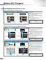
Motion SFC Program
Motion SFC operation
PLC program (Note)
Motion SFC program
All steps are executed with constant scanning
Only active steps are executed following transition conditions
X0000
PLS
M100
SET
M101
Work travel control
M100
[G 1]
PX0 //Start (PX0:ON) wait
M101 M2001 M2002
RST M101
[K 1]
1 ABS-2
Axis
1,
# 200
Axis
2,
# 202
Combined-speed # 204
SET
[G 2]
PX1 //1st process machining completion (PX1: ON) wait
SVST J1 J2
K1
M102
M102 M2001
SVST J1
[K 2]
1 ABS-1
Axis
Speed
K2
1,
# 300
# 302
m
m
mm/min
High-speed response using step execute method
■ The PLC program uses a scan execute method to execute all steps with constant scanning. However,
since the step execute method which executes only
the active steps following the transition conditions is
used in the Motion SFC program, the operation processing can be reduced, and processing or response
control can be realized.
m
mm/min
RST M102
SET
M103
SET
Y0008
[G 3]
PX2 //2nd process machining completion (PX2: ON) wait
[F 1]
SET PY8 //Complete signal (PY8) ON
M103 M2001
END
RST M103
(Note): A172SHCPUN, SV13 use
Shift
WAIT
WAIT ON/OFF
K100
K200
ON M0
G100
G200
K300
■ Execute G100 without waiting for
K100 operation to end
■ Execute G200 after waiting for
K200 operation to end
■ Pre-read K300 and prepare to start
■ Start immediately with the
specified bit (M0) ON
Selective branch
GO
G1
G2
G3
K2
K3
F1
K2
K3
K4
G1
G2
G3
G6
F2
G4
G4
Wait
■ Judge G1 to G3 conditions, and execute only
completed route
P
F
P
G
Parallel branch
K
F
K
G
G
G
F
F
F
F
F
G
G
G
K
K
P
G
END
G
F
P
15
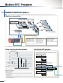
Multi-task processing
SUB
F
F
■ When all routes after branch are shift or WAIT, selective branch is used.
Parallel branch is used in all other cases.
■ The route for which the transition conditions are completed first are executed in the selective branch.
■ The routes connected in parallel are executed simultaneously, the processing waits at the connection
point, and shifts to the next process after execution of
all routes is completed in the parallel branch.
■ Simultaneously execute all routes for step K2 to
F1 in parallel
REAL
MAIN
■ If shift is executed immediately after the motion control step, the shift is executed without waiting for the
motion control operation to end.
■ If WAIT is executed immediately after the motion control step, WAIT will be executed after waiting for the
motion control operation to end.
■ If WAIT ON/WAIT OFF is executed just before the
motion control step, the details of the motion control
will be pre-read, and preparations for start are made.
The operation starts immediately with the specified bit
device ON/OFF.
Selective branch and parallel branch
Parallel branch
K1
Dedicated description unique to motion control
Selective branch
■ When the multiple programs are started, the processing is executed with multi-task operation in the Motion
SFC program.
■ Multiple steps can be simultaneously executed with
parallel branching even in one program.
■ A program that executes the multiple processing simultaneously or makes the independent movement
by grouping the control axes can be created easily.
■ A highly independent programming is possible according to the processing details, so a simple program can be created.
III
Task operation examples of Motion SFC program
Normal task
Program 1
Program 2
• Normal task
• Do not start automatically
F20
F30
F1
F5
F2
F6
F3
F7
END
F8
• Normal task
• Do not start automatically
END
Timing chart
S(P).SFCS (Program 1 start)
S(P).SFCS (Program 2 start)
PLC program
Main cycle
Main cycle
Main cycle
Execute timing of normal task
(Program 1, Program 2)
Event task/NMI task
Program 1
F100
Program 2
• Event task
(External interrupt, PLC interrupt)
• Do not start automatically
F200
F110
F210
F120
F220
F130
F230
F140
F240
END
END
Timing chart
• Event task
(Fixed cycle : 1.77ms)
• Do not start automatically
S(P).SFCS (Program 1 start)
S(P).SFCS (Program 2 start)
S(P).GINT (Execute reguest of event task)
PLC program
EI/DI state by other program
EI
DI
EI
External interrupt
Execute timing of event task
(Program 1)
Memorize event occurrence
during DI, and execute
1.77ms
Fixed cycle interrupt (1.77ms)
Execute timing of event task
(Program 2)
Event task execute disable during DI
Execute with new event
(Note): Number of steps executed in 1 time of processing cycle are set in the parameters.
16
Motion SFC Program
Motion SFC high-speed response control
High-speed response to external inputs
PLC program
Motion SFC program
I/O output
■ The response time of output signal for the
M100
X10
[G100]
SET PY0 = PX10 M100
Y0
input signal from an external source is
measured in this program.
■ The response time and dispersion affected
by the scan time are approx. 6.5ms in the
PLC program.
■ There are neither the response nor dispersion in the Motion SFC program.
PLC scan time 5ms
X10
(Input)
PX10
(Input)
OFF
OFF
ON
Y0
(Output)
ON
PY0
(Output)
OFF
OFF
Measurement machine used
ON
ON
5ms/div
5ms/div
~6.5ms
(Approx. PLC scan time)
~1ms
PLC CPU module
Motion CPU module
Input module
Output module
:Q02HCPU
:Q173HCPU(-T)
:QX40-S1(OFF➝ON response:~0.1ms)
:QY40P(OFF➝ON response:~1ms)
Powerful reduction in servo program start time
PLC program
X10 U3E1¥G48.0
Motion SFC program
U3E1¥G516.0
Servo program start
ON PX0010
SP.SVST "J1"
K100 M0 D0
K100
PLC scan time 5ms
OFF
X10
(Input)
ON
PX10
(P-I/O input)
OFF
ON
Speed command
(Amplifier monitor terminal)
Speed command
(Amplifier monitor terminal)
10ms/div
10ms/div
~5ms
~1.7ms
PLC program
U3E1
¥G516.0
Motion SFC program
U3E1
¥G516.1
G100
U3E1
¥G516.0
U3E1
¥G516.2
RST M10
K300
SP.SVST "J1J3" K300 M30 D30
PLC scan time 5ms
Speed command
Axis 1
Speed command
Axis 1
Axis 2
Axis 2
Axis 3
Axis 3
10ms/div
~8.5ms
(Approx. "PLC scan time + 3ms")
17
10ms/div
~3.3ms
:Q02HCPU
:Q173HCPU(-T)
:QX40-S1(OFF➝ON response:~0.1ms)
Servo program continuous start
■ 1 axis, 3 axes linear interpolation program
“K300” is started following 1 axis, 2 axes
linear interpolation program “K200” in this
example.
■ The response time and dispersion are approx. 8.5ms in the servo program continuous start using the PLC program. This is
because the PLC scan time is 5ms and the
refresh cycle of start accept flag used as
the interlock is approx. 3 ms.
■ An interlock is not required and the start
delay is approx. 3.3ms in the Motion SFC
program.
K200
SP.SVST "J1J2" K200 M20 D20
U3E1
M20 ¥G48.0
Measurement machine used
PLC CPU module
Motion CPU module
Input module
(Approx. PLC scan time)
U3E1
M10 ¥G48.0
■ The servo program is started using the input signal from an external source as a
trigger in this example.
■ The response time and dispersion are affected by the scan time from the external
signal input to starting of speed command
are approx. 5ms in the start using the PLC
program.
■ The speed command is started with the response time “dispersion approx. 1.7ms” in
the Motion SFC program.
Measurement machine used
PLC CPU module
Motion CPU module
Input module
:Q02HCPU
:Q173HCPU(-T)
:QX40-S1(OFF➝ON response:~0.1ms)
III
Motion SFC specifications
Motion SFC chart symbols
Class
Name
Symbol
START
Program
start/end
Step
Program name
Function
Indicates the program start (entrance) .
END
END
Indicates the program end (exit) .
Motion control step
K
Starts the servo program Kn.
(Refer to page 22 for the servo instructions.)
Once execution type operation control step
F
Executes the operation control program Fn once.
Scan execution type operation control step
FS
Subroutine call/start step
Repeats an operation control program FSn until the completion of next transition condition.
Program name
Clear step
CLR Program name
Shift (Pre-read transition)
G
WAIT
G
Calls or starts a subroutine.
Cancels and ends the execution of specified program.
Shifts to the next step with the completion of condition without waiting for the previous
motion control step or subroutine to end.
Shifts to the next step with the completion of condition after the previous motion control
step or subroutine end.
Transition
WAIT ON
ON bit device
WAIT OFF
OFF bit device
Prepares to start the next motion control step, and immediately commands the completion
of condition.
Jump
Jump
P
Jumps to the specified pointer Pn of the self program.
Pointer
Pointer
P
Indicates the jump destination pointer (label).
Motion SFC program parameters
The Motion SFC program start method and execute timing are set with the program parameters.
Details
Setting range
Item
Start setting
Execute task
Start automatically
• Starts at the turning PLC ready (M2000) off to on.
Do not start automatically
• Starts with the Motion SFC program start instruction S(P).SFCS .
• Starts with the "Subroutine call/start" GSUB from the Motion SFC program.
Normal task
• Executes in the motion main cycle (free time).
Event task
Fixed cycle
• Executes in the fixed cycle (0.88ms, 1.77ms, 3.55ms, 7.11ms, 14.2ms).
External interrupt
• Executes when input ON is set among the input 16 points of the interrupt module QI60.
PLC interrupt
• Executes with interrupt instruction from PLC.
• Executes when input ON is set among the input 16 points of the interrupt module QI60.
NMI task
Operation control steps and transition commands
Class
Binary
operation
Bit
operation
Sign
Type
conversion
Symbol
=
+
–
*
/
%
˜
&
I
ˆ
>>
<<
–
SHORT
USHORT
LONG
ULONG
FLOAT
UFLOAT
Function
Substitution
Addition
Subtraction
Multiplication
Division
Remainder
Bit inversion (complement)
Bit logical AND
Bit logical OR
Bit exclusive logical OR
Bit right shift
Bit left shift
Sign inversion (complement of 2)
Signed 16-bit integer value conversion
Unsigned 16-bit integer value conversion
Signed 32-bit integer value conversion
Unsigned 32-bit integer value conversion
Signed 64-bit
floating-point value conversion
Unsigned 64-bit
floating-point value conversion
Class
Symbol
Function
SIN
COS
TAN
ASIN
ACOS
ATAN
SQRT
LN
EXP
ABS
RND
FIX
FUP
BIN
BCD
(none)
!
SET
RST
DOUT
DIN
OUT
Sine
Cosine
Tangent
Arcsine
Arccosine
Arctangent
Square root
Natural logarithm
Exponential operation
Absolute value
Round-off
Round-down
Round-up
BCD → BIN conversion
BIN → BCD conversion
ON (normally open contact)
OFF (normally closed contact)
Device set
Device reset
Device output
Device input
Bit device output
Standard
function
Bit device
status
Bit device
control
Motion dedicated PLC instructions
Instructions
S(P).SFCS
S(P).GINT
S(P).SVST
S(P).CHGA
S(P).CHGV
S(P).CHGT
S(P).DDWR
S(P).DDRD
Control details
Class
Logical
operation
Comparison
operation
Motion
dedicated
function
Others
Symbol
(none)
!
*
+
==
!=
<
<=
>
>=
CHGV
CHGT
EI
DI
NOP
BMOV
FMOV
TIME
Function
Logical acknowledgement
Logical negation
Logical AND
Logical OR
Equal to
Not equal to
Less than
Less than or equal to
More than
More than or equal to
Speed change request
Torque limit value change request
Event task enable
Event task disable
No operation
Block transfer
Same date block transfer
Time to wait
MULTW
Write device data to shared
CPU memory
MULTR
Read device data from shared
CPU memory of the other CPU
TO
Write device data to intelligent function
module/special function module
FROM
Read device data from intelligent function
module/special function module
Start request of the Motion SFC program (Program No. may be specified.)
Execute request of an event task of Motion SFC program
Start request of the specified servo program
Current value change request of the specified axis
Speed change request of the specified axis
Torque control value change request of the specified axis
Write from the PLC CPU to the Motion CPU
Read from the devices of the Motion CPU
18
Motion SFC Program
Example of Motion SFC program
■ This is a control example of assortment equipment which judges 3 types work and performs assortment conveyance on 3 lines.
Machine composition
Length judgement Work detected
sensor
timing sensor
Long work :PH1 to PH3 ON
Middle work :PH2 and PH3 ON
Short work :Only PH3 ON
PH1 PH2
PH3 PH0
Work detected
sensor (IN)
PH4
Work detected
sensor (OUT)
PH5
Ball
screw
a-point
Inport
conveyer
Long work
export conveyor
Work
b-point
Middle work
export conveyor
(Waiting point)
Length:3 types
Servo
amplifier
(Note) : Control of inport/export
conveyor is not included.
I/O signal allocation
PX0:Work detected timimg sensor PH0
PX1:Length judgement sensor PH1
PX2:Length judgement sensor PH2
PX3:Length judgement sensor PH3
PX4:Work detected sensor PH4(IN)
PX5:Work detected sensor PH5(OUT)
Short work
export conveyor
Geared
motor (GM)
Servomotor
(Axis 1)
PB, SW
Motion controller
c-point
Motion dedicated device allocation
PX6:Automatic mode selection SW
PX7:Automatic start PB
PX8:Automatic cycle temporary stop SW
PX9:Forward rotation JOG PB
PXA:Reverse rotation JOG PB
PXB:Conveyor JOG PB
M2001:Axis 1 start accept monitor
M2042:All axes servo ON command
M2402:Axis 1 in-position signal
M3200:Axis 1 stop command
M3202:Axis 1 forward rotation JOG command
M3203:Axis 1 reverse rotation JOG command
PY10:Conveyor GM drive output
✽ “Real input/output” is expressed as “PX/PY” in the Motion CPU.
Main Motion SFC program
Timing chart of automatic operation
Length judgement
(Example for long work)
Operating mode switching program (Automatic start)
PX0
PX1
Operation mode switching
PX2
[F110]
SET M2042 //All axes servo ON command
PX3
PX4
P0
PX5
PX6
[G105]
M2415 //Axis 1 servo ON ?
PX7
Servomotor
(Axis 1)
b-point
(Waiting point)
a-point
(Long work)
b-point
(Waiting point)
[G110]
PX6 //Automatic operation mode ?
PY10
Geared motor
• PX6 ON : Call “Automatic operation”
• PX6 OFF : Call “Manual operation”
Work input
Work output
Automatic operation
Manual operation
Automatic operation 1 cycle
Operation specifications
■ Automatic operation mode is set by turning the automatic mode selection SW(PX6) ON, and manual
operation mode is set by OFF.
■ Manual operation mode
• JOG operation of servomotor is executed with the forward rotation JOG (PX9)/reverse rotation JOG (PXA).
• JOG operation (export direction only) of geared motor is executed with the conveyor JOG PB (PXB).
■ Automatic operation mode
• Automatic operation cycle (assortment conveyance) shown in a chart is started by turning the automatic
start PB (PX7) ON.
• Automatic operation cycle is stopped temporality by turning the automatic cycle temporary stop SW (PX8)
ON, and it is resumed by OFF.
• Automatic operation cycle is stopped by turning the automatic mode selection SW (PX6) OFF, and it shifts
to the manual operation mode.
19
[G115]
//Wait a subroutine call completion
NOP
P0
III
Sub Motion SFC program
Automatic operation program (Not automatic start)
Automatic operation
• Subroutin end with PX6 OFF
[G10]
PX7 //Automatic start ON?
[G20]
!PX6 //Switch to manual operation mode?
P0
END
• Positioning to b-point (Waiting point)
[K150:Real]
1 ABS-1
Axis 1, 400000.0 m
Speed 10000.00mm/min
[G140]
M2402 //Axis 1 in-position signal ON?
• Waiting for work detection
[G150]
// (Work detection timing sensor ON)
//AND (Automatic cycle temporary stop OFF)?
PX0 !PX8
[G152]
!PX6 //Switch to manual operation mode?
END
• Selective branch based on detection
result length judgement sensor
[G154]
PX1 PX2 PX3 //Long work?
[G156]
!PX1 PX2 PX3 //Middle work?
[G158]
!PX1 !PX2 PX3 //Short work?
[F150]
#0L=6000000 //a-point position set
[F152]
#0L=4000000 //b-point position set
[F154]
#0L=2000000 //c-point position set
[G160]
PX4 //Work detected sensor (IN) ON?
[F156]
SET PY10 //Conveyor start
• Parallel branch
(Execute 2 routes simultaneously)
[G162]
!PX4 //Work detected sensor(IN) OFF?
[G164]
PX5 //Work detected sensor(OUT) ON?
• Positioning to a, b or c-point based on work length
[K152:Real]
1 ABS-1
Axis
1,
# 0 m
Speed
10000.00mm/min
[F158]
RST PY10 //Conveyor stop
[G140]
M2402 //Axis 1 in-position signal ON?
• Wait until completion of 2 routes
[F160]
SET PY10 //Conveyor start
[G168]
!PX5 //Work detected sensor (OUT) OFF?
[F162]
RST PY10 //Conveyor stop
P0
Manual operation program (Not automatic start)
Manual operation
[F120]
//Axis 1 JOG operation speed set
D640L=100000
• JOG operation of servomotor (axis 1)
and geared motor (GM)
• Repeat until PX6 is turned on
[G120]
//Axis 1 forward rotation JOG command SET/RST
SET M3202=PX9 !M3203
RST M3202=!PX9
//Axis 1 reverse rotation JOG command SET/RST
SET M3203=PXA !M3202
RST M3203=!PXA
//GM drive output SET/RST
SET PY10=PXB
RST PY10=!PXB
//Repeat until automatic mode switching
PX6
• JOG command is turned off with PX6
OFF, and subroutine end
[F122]
//Axis 1 forward/reverse rotation JOG command RST
RST M3202
RST M3203
//GM drive output RST
RST PY10
END
20
SV13 (Conveyor Assembly Use)
Simple Programming Using Dedicated Instructions
■ Colorful positioning controls and locus controls such as “1 to 4 axes linear interpolation, 2 axes circular interpolation, helical
interpolation, positioning control, speed control or constant-speed control” are supported. Particularly simple programming for
positioning systems is attained by using dedicated servo and PLC instructions.
A variety of enhanced functions allow easy programming of conventionally complex systems.
Control flow
PLC CPU
Motion CPU
PLC program
Motion SFC program
SP.SFCS
......
K0
......
......
Motion SFC
program start
request instruction
Start program No. specification
✽ Motion SFC program also can be automatically
started by the parameter setting.
2-axes constant-speed control
[G100]
M2049 // Servo ON accept ?
Servo amplifier
Servomotor
Servo program
[K10 : Real]
5 CPSTART2
Axis
1,
Axis
2,
Speed 1000.00mm/min
2-axes constant-speed control
1 INC-2
Axis
Axis
Incremental linear interpolation
Combined-speed setting
1, 10000.0 m
2, 12500.0 m
2 ABS
Axis
1, 18500.0
Axis
2, 7500.0
Auxiliary P 1, 13500.0
Auxiliary P 2, 14750.0
M-code
m
m
m
m
10
Absolute auxiliary point specified
circular interpolation
M-code output
3 ABS-2
Axis
1, D 2000 m
Axis
2, D 2002 m
M-code
11
Absolute linear interpolation
4 ABS-2
Axis
1,
0.0 m
Axis
2,
0.0 m
M-code
12
Speed 800.00mm/min
Absolute linear interpolation
Indirect setting
M-code output
M-code output
Combined-speed setting
5 CPEND
END
Positioning parameter
System setting
Fixed parameter
Servo parameter
Parameter block
Axis 2
14750
12500
7500
Home position return data
JOG operation data
Limit switch setting
21
2500
10000
16000 Axis 1
13500 18500
III
Servo instructions
INC-3
Incremental 3-axes linear
interpolation
ABS-4
Absolute 4-axes linear
interpolation
INC
INC
INC
Absolute radius-specified
circular interpolation less than
CW 180˚
Absolute radius-specified
circular interpolation CW 180˚
or more
Absolute radius-specified
circular interpolation less than
CCW 180˚
Absolute radius-specified
circular interpolation CCW 180˚
or more
Incremental radius-specified
circular interpolation less than
CW 180˚
Incremental radius-specified
circular interpolation CW 180˚
or more
Incremental radius-specified
circular interpolation less than
CCW 180˚
Incremental radius-specified
circular interpolation CCW 180˚
or more
ABS
Absolute central point-specified
circular interpolation CW
ABS
Absolute central point-specified
circular interpolation CCW
INC
Incremental central point-specified
circular interpolation CW
INC
Incremental central point-specified
circular interpolation CCW
INH
ABH
Absolute central point-specified
helical interpolation CW
ABH
Absolute central point-specified
helical interpolation CCW
INH
Incremental central point-specified
helical interpolation CW
INH
Incremental central point-specified
helical interpolation CCW
FEED-1
1-axis fixed-pitch feed start
FEED-2
2-axes linear interpolation
fixed-pitch feed start
FEED-3
3-axes linear interpolation
fixed-pitch feed start
VF
Speed control (!) forward rotation
start
VR
Speed control (!) reverse rotation
start
VVF
Speed control (@) forward rotation
start
VVR
Speed control (@) reverse rotation
start
Teaching function
Portable teaching units, perfect on-site environments.
In addition, they also have servo programming
functions,data setting, servo monitor and servo testing
function.
Also, because the A31TU-D3K13 is fitted with 3position deadman switch, error safety is assured.
●A31TU-D3K13(With 3-position deadman switch)
●A31TU-DNK13
VPR
Speed-position control
reverse rotation start
VPSTART
Speed-position control restart
VSTART
Speed switching control start
VEND
Speed switching control end
VABS
Speed switching point
absolute specification
VINC
Speed switching point
incremental specification
PVF
Speed control with fixed
position stop absolute specification
PVR
PFSTART
Position follow-up control start
CPSTART1
1-axis constant-speed control start
CPSTART2
2-axes constant-speed control start
CPSTART3
3-axes constant-speed control start
CPSTART4
4-axes constant-speed control start
CPEND
Current value change
INC
INH
Central point-specified
ABS
INH
Incremental auxiliary point-specified
circular interpolation
Fixed-pitch feed
INC
Absolute auxiliary point-specified
circular interpolation
INH
Reverse Forward Reverse Forward
1 axis
rotation rotation rotation rotation 3 axes 2 axes
ABS
Incremental 4-axes linear
interpolation
ABH
Restart Reverse Forward
rotation rotation
ABH
VPF
Constant-speed control end
FOR-TIMES
FOR-ON
Repeat range start setting
FOR-OFF
NEXT
Repeat range end setting
START
Simultaneous start
ZERO
Home position return start
OSC
High-speed oscillation start
CHGA
Servo/virtual servo current value
change
Encoder
Absolute 3-axes linear
interpolation
Processing
Speed-position control
forward rotation start
CHGA-E
Encoder current value change
CAM
ABS-3
Speed-position
control
ABH
Speed switching control
INC-2
Incremental 2-axes linear
interpolation
Absolute radius-specified
helical interpolation less than
CW 180˚
Absolute radius-specified
helical interpolation CW 180˚
or more
Absolute radius-specified
helical interpolation less than
CCW 180˚
Absolute radius-specified
helical interpolation CCW 180˚
or more
Incremental radius-specified
helical interpolation less than
CW 180˚
Incremental radius-specified
helical interpolation CW 180˚
or more
Incremental radius-specified
helical interpolation less than
CCW 180˚
Incremental radius-specified
helical interpolation CCW 180˚
or more
Position Speed control
with fixed
follow-up
control position stop
ABH
Radius-specified
Absolute 2-axes linear
interpolation
Helical interpolation control
ABS-2
Constant-speed control
Incremental auxiliary point-specified
helical interpolation
Positioning Instruction
control
symbol
Repetition of same control
High- Home Simulta(used in speed switching
speed position neous
start
return
oscillation
control, constant-speed control)
Servo
Auxiliary
point-specified
INH
Incremental 1-axis positioning
ABS
Radius-specified
ABH
INC-1
INC-4
Processing
Absolute auxiliary point-specified
herical interpolation
Absolute 1-axis positioning
ABS
Central point-specified
Positioning Instruction
control
symbol
ABS-1
ABS
Circular interpolation control
Processing
Speed control Speed control
(@)
(!)
2 axes
3 axes
Auxiliary
point-specified
4 axes
Linear interpolation control
1 axis
Positioning Instruction
control
symbol
CHGA-C
CAM shaft current value change
3-position deadman switch
(Front panel)
(Rear panel)
Teaching unit
(Note): In planning stages
22
SV13 (Conveyor Assembly Use)
Application examples
X-Y table
Sealing
●Constant-speed locus control
●Linear, circular interpolation
●High speed, high-precision locus operation
●2-axes linear interpolation
●3-axes linear interpolation
●2-axes circular interpolation
●Constant-speed locus control
Z-axis
r1
r2
X-axis
Z
X
Y
Y-axis
Drilling machine
Fixed-pitch stamping machine
●Speed-switching control
●Speed/position switching control
Position sensor
1st speed
Servomotor
2nd speed
Speed
control
Speed
switching
(High-speed
recovery)
Speed
Speed
Speed
switching
3rd speed
Pause (Torque control)
Torque
limit value
Position
control
Time
Sensor operation
Stamp
Time
(Note) : There is not limit of number of speed-switching points.
Spinner
Roll feeder
●Fixed-pitch feed
●High speed, high frequency positioning
●High speed response
●Rotary shaft specified position stop
●Speed control
●Speed, acceleration/deceleration time change during operation
Speed
Press
Rotates at a fixed speed
Feeder
speed
Roll
feeder
Feeder
position
command
Servomotor
Stop at preset position
Upper dead point
Servomotor
Press stroke
Lower dead point
23
Time
III
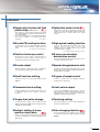
Functions
■ Speed control function with fixed
position stop (Orientation function)
The servomotor can be rotated at present speed and
then stopped at present position after the fixed position
stop command ON.
Not only the speed but also acceleration/deceleration
time can be changed to an optional value while
operating.
Uses : Spinner
■ Optional data monitor function
Data(effective load ratio, regenerative load ratio, bus
voltage, etc.) can be monitored by setting the data type
and storage device of monitor data in the system
setting.
■ M-code FIN waiting function
■ High speed reading function
Positioning start to the next point during constantspeed control can be executed at high speed than
usual.
Up to 11 data among 16 types(feed current value,
deviation counter value, etc.) can be read
simultaneously to the specified device using a signal
from input module as a trigger.
Uses : High response positioning start
Uses : Measured length, synchronized correction
■ Position follow-up control
By starting once, the set value of positioning point is
detected in real time, and the position control is
executed by following the changing set value.
■ M-code output
M-codes between 0 and 32767 can be outputted at
each positioning point during positioning operation.
■ Dwell time free setting
Dwell time can be set for any value between 0 and
5000 ms.
■ Parameter block setting
Common setting items in positioning control can be set
as parameter blocks up to 64 types, and freely
selected.
■ Torque limit value change
Torque limit value change can be simply executed
during positioning and JOG operation using the Motion
dedicated instruction CHGT.
■ Indirect setting of home
position return data
A part of home position return data can be executed
the indirect setting by the word devices(D,W,#) of the
Motion CPU.
■ S-curve acceleration/
deceleration control
The acceleration/deceleration characteristics can be
set with the optional ratio S-curve.
■ Speed change/pause/re-start
Positioning, speed change during JOG operation and
pause/re-start can be executed simply using the Motion
dedicated instruction CHGV.
■ 2 types of speed control
2 types of speed control are available using the
position loops or speed loops.
■ Limit switch output
Up to 32 points ON/OFF output signal for the real
current value, motor current and word device data, etc.
during operation can be outputted at high-speed
regardless of the Motion SFC program.
■ Teaching setting
The positioning points can be set with teaching in the
test mode of MT Developer.
■ Gain changing function
The gain changing of servo amplifier can be executed
in the Motion controller by gain changing command
ON/OFF.
24
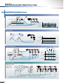
SV22 (Automatic Machinery Use)
Easy On-Screen Programming Using the Mechanical Support Language
■ Incorporating a mechanical support language that allows easy programming of the mechanical system.
By combining a variety of software mechanical modules and cam patterns, complex synchronized control and coordinated control
can be achieved easily and at low-cost.
Ideal for controlling automatic machinery such as food processing and packaging.
Control flow
PLC CPU
Motion CPU
PLC program
Motion SFC program
SP.SFCS
......
K0
......
Virtual servomotor start
in the mechanical system program
Conveyor start
......
Drive module
Transmission module
[G200]
M2044 // On virtual mode?
Motion SFC
program start
request instruction
(Gear)
Servo program
Start program No. specification
✽ Motion SFC program also can be automatically
started by the parameter setting.
[K 100 : Virtual]
1 VF
Axis 1,
Combine #
(Clutch)
(Virtual servomotor)
0
PLS/s
Output
module
END
Positioning parameter
System setting
(Cam)
Operation results from
the transmission module
are output to the servo
amplifier set in the output
module.
Fixed parameter
Servo parameter
Parameter block
Limit switch setting
(Roller)
Servo amplifier
Servo amplifier
Servomotor
Servomotor
Mechanical modules
Class
Mechanical Module
Name
Appearance
Function Description
Virtual
servomotor
• It is used to drive the virtual axis of mechanical system
program by the servo program or JOG operation.
Synchronous
encoder
• It is used to drive the virtual axis by the input pulses
from the external synchronous encoder.
Virtual main
shaft
• This is a virtual “link shaft”.
• Drive module rotation is transferred to the transmission
module.
Virtual
auxiliary
input axis
• This is the auxiliary input axis for input to the
differential gear of transmission module.
Class
Mechanical Module
Name
Speed change
gear
Drive
module
Virtual
axis
Gear
Transmission
module
Direct clutch
Smoothing
clutch
25
• The drive module rotation is transmitted to the output
axis.
• A setting gear ratio is applied to the travel value
(pulse) input from the drive module, and then transmits
to the output axis that it becomes in the setting rotation
direction.
• Transmit or separate the drive module rotation to the
output module.
• There are a direct clutch transmitted directly and the
smoothing clutch which performs the
acceleration/deceleration and transmission by the
smoothing time constant setting at the switching
ON/OFF of the clutch.
• It can be selected the ON/OFF mode, address mode or
the external input mode depending on the application.
• Time constant system or slippage system can be
selected as a smoothing system.
Appearance
Function Description
• It is used to change speed of output module (roller).
• The setting speed change ratio is applied to input axis
speed, and transmits to the output axis.
• Auxiliary input axis rotation is subtracted from virtual
main shaft rotation, and the result is transmitted to the
output axis.
Transmission
module
Differential
gear
• Auxiliary input axis rotation is subtracted from virtual
main shaft rotation, and the result is transmitted to the
output axis.
(Connect to the virtual main shaft)
Roller
• It is used to perform the speed control at the final
output.
Ball screw
• It is used to perform the linear positioning control at
the final output.
Rotary table
• It is used to perform the angle control at the final
output.
Cam
• It is used to control except the above. Position control
is executed based on the Cam pattern setting data.
• There are 2 Cam control modes: the two-way Cam and
feed Cam.
Output
module
III
Mechanical support language
Realizing mechanical operation using software
Easy programming on screen using a mouse
By replacing the mechanical system of main shafts,
gears, clutches, and cams with the software mechanical
modules, the following merits can be realized.
● Machine is more compact and costs are lower.
● There are no worries over friction and service life for
the main shaft, gear and clutch.
● Changing initial setup is simple.
● There is no error caused by mechanical precision, and
system performance improves.
Advanced control using electronic cam
Ideal cam pattern control was achieved without problems,
such as an error produced in the conventional cam control, by processing the cam control by software. The cam
control for the nozzle lowering control in contact with liquid surfaces, amount of filler control or smooth conveyance control, etc. can be realized simply. Exchanging of
cam for product type change is also possible easily by
changing the cam pattern only.
Programming monitor by mechanical support language
Cam data creation software SW3RN-CAMP
By using the cam data creation software (SW3RN-CAMP), the cam pattern (form) is set to excute the electronic cam control by
mechanical support language.
Flexible and highly precise cam patterns can be created to match the required control. Complex cam patterns are easy to
program.
Creating Cam pattern
11 types of cam patterns
Whatever cam curve you need can be created, by selecting and combinig
cam patterns suited to your application among 11 types.
Constant-speed Constant-acceleration 5th curve Cycloid Distorted trapezoid
Cam
Distorted sine Distorted constant-speed Trapecloid Reverse trapecloid
patterns
Single hypotenuse Double hypotenuse
Can be set by free-form curves
Cam curves can be set by free curves using spline interpolation.
Graphic display of control state
Selectable cam precision to match application
The resolution per cycle of cam can be set in the following four stages.
256
512
1024
2048
Graphic display of control status
Control status information such as stroke ratio, speed and acceleration can
be displayed in simple graphics.
26
SV22 (Automatic Machinery Use)
Application examples
Filling machine
Filling
Nozzle raised and lowered
Conveyance
stroke
Nozzle stroke
Filling stroke
Time
Draw control
V
V+Draw
Speed
Roller 1 : V
Speed
Roller 2 : V+Draw
Press conveyance
Work
Press
arangement extraction
Conveyor
Conveyor
import
export
Press
Press machine
Main press motor
Import conveyor
Work
Die
Synchronous
encoder
Rotation
angle
Export conveyor
Work
Y-axis stroke
X-axis servomotor
–
+
+
X-axis stroke
Y-axis servomotor
–
Printing machine
●Mark detection function
●Synchronous operation
between axes
●Tandem operation
●Torque control
Printing part
Processing part
(Note) : Consult individually about the case applied to a printing machine.
(It is necessary to use the operating system software, servo amplifiers and servomotors with special specification according to the system.)
27
III
Three dimensional transfer
Lift (2)
Lift AC servomotor
Feed
Lift (1)
Lift AC servomotor
Feed
AC servomotor
Clamp (2)
Clamp
AC servomotor
Clamp (1)
Rotation angle
Feed stroke
Cramp stroke
Lift stroke
New function
■ Phase compensation
When carrying out tracking synchronization with the
synchronous encoder, the deviation between the
synchronous encoder and servomotor shaft end can be
eliminated by phase compensation.
■ Smoothing clutch linear acceleration/
deceleration function
In the smoothing clutch, the linear acceleration/
deceleration system can be selected.
The impact of servomotor immediately after ON/OFF of
clutch can be eased compared with the past
exponential function system.
■ Mixed function of virtual mode
with real mode
The positioning control (real mode operation) can be
executed for the axis set to the real mode axis in the
virtual mode.
■ Smoothing clutch completion
signal output function
The signal turned on in proportion to the remainder of
clutch slippage was added.
It is possible to use it for the judgment of the following
synchronous clutch ON completion.
Synchronous control
The servomotor can be operated by making it synchronous with other motor control conditions.
Synchronous operation with simple setting for synchronous control and little tracking delay can be realized by a mechanical support language.
A
T
B
3000r/min
Motor speed
Drive module
Transmission module
Gear
0.05˚
Position deviation
between 2-axes
0.05˚
Output module
(Virtual servomotor)
50ms
Roller
1-axis position deviation
2-axes position deviation
1-axis
Position deviation between axes
2-axes
Mechanical system program
28
Integrated Start-Up Support Software MT Developer
Various programming tools in a effective background on Windows
■ The operativeness of effective background on Windows is made the best use of, and the best programming and
maintenance for Motion controller is prepared.
System design
Integrated start-up support software MT Developer
System setting
Servo parameter setting
■ Direct start of MT
Developer in the
perameter setting
screen
Start-up adjustment
Programming
■ Set the system configuration (Motion module,
servo amplifier) with menu selection
Motion SFC program editing
Select instruction
Instruction
wizard
■ Describe machine operation procedures with flow chart format
■ Lay out graphic symbols by clicking mouse and connect by dragging
■ Program for each step and transition
■ Selection with menu is also possible using command wizard
Motion SFC monitor
Motion SFC debugging mode
■ Color indication of executing step on flow chart
■ Device monitor and test of execution/specification step
■ Greatly reduced debugging time with powerful debug function
(One-step execution/Forced shift/Brake/Forced end)
Monitor • Test
Digital
oscilloscope
■ Current value monitor/Axis monitor/Error history monitor
■ Various tests such as home position return/JOG operation by
clicking mouse
29
Program editing
■ Data sampling synchronized with motion control cycle
■ Waveform display/Dump display/File save/Printing
III
Integrated start-up support software MT Developer
Software
Installation
Project management
System setting
Servo data setting
Conveyor assembly software
SW6RN-GSV13P
Automatic machinery software
SW6RN-GSV22P
Program editing
Mechanical system editing
(GSV22P only)
Communication
Monitoring
Test
Backup
Cam data creation software
SW3RN-CAMP
Digital oscilloscope software
SW6RN-DOSCP
Cam data creation
Digital oscilloscope
Function
• Installation of operating system (OS)
• Comparison of operating system (OS)
• New creation, setting and reading of projects
• Batch management of user files in project units
• Setting of system configuration (Motion module, servo amplifier or servomotor, etc.)
• Setting of high-speed reading data
• Setting of servo parameters or fixed parameters, etc.
• Setting of limit switch output data
• Editing of servo program
• Editing of Motion SFC program/Setting of Motion SFC parameters
• Reduced display, comment display and extended display of Motion SFC chart
• Motion SFC monitor/Motion SFC debug
• Editing of mechanical system program
• Monitoring of mechanical system program execute state
• Setting of SSCNET communication CH/Communication setting between USB and RS-232
• Writing, reading and comparison of programs and parameters for Motion controller
• Current value monitor/Axis monitor/Error history monitor
• Axis state monitor/Limit switch output monitor
• Servo startup/Servo diagnosis
• Jog operation/Manual pulser operation/Home position return test/Program operation
• Teaching/Error reset/Current value change
• Backup of Motion controller programs and parameters in file
• Batch writing of backed up files to Motion CPU
• Cam data creation with Cam pattern selection and free curve settings
• Graphic display of Cam control state
• Data sampling synchronized to operation cycle
• Waveform display, dump display and file saving of collected data
Communication system software Communication system
Communication API
SW6RN-SNETP
• Communication task/Communication manager/Common memory server/SSCNET
communication driver
• Support of cyclic communication, transient communication, high-speed refresh communication
• Communication API functions compatible with VC++/VB
Document printing software
SW3RN-DOCPRNP (Note-1)
SW20RN-DOCPRNP (Note-2)
• Printing of programs, parameters and system settings
(Convert into Office 97 or Office 2000 document format, and print)
Printing
(Note-1) : Office 97 are required.
(Note-2) : Office 2000 are required.
Operating environment
IBM PC/AT with which WindowsNT4.0/98/2000/XP English version operated normally.
®
Item
CPU
Memory capacity
Hard disk free space
Display
Application software
®
®
WindowsNT 4.0 (Service Pack 2 or later)
Windows 2000
Windows XP
®
or Windows 98
Recommended Pentium® 133MHz or more Recommended Pentium® 233MHz or more Recommended Pentium® 450MHz or more
Recommended 32MB or more
Recommended 64MB or more
Recommended 192MB or more
SW6RNC-GSVE: 333MB + SW6RNC-GSVHELPE: 155MB (Possible to select installation)
SVGA (Resolution 800 ✕ 600 pixels, 256 colors) or more
Office 97 or Office 2000 (For document printing)
Visual C++ 4.0 or more, Visual Basic 4.03 (32 bit) or more (For communication API function)
®
(Note) • When using the A30CD-PCF, the PC card driver for WindowsNT provided by the personal computer manufacturer must be used.
®
®
®
• WindowsNT , Windows , Office , Visual C++ and Visual Basic are either registered trademarks or trademarks of Microsoft Corporation in the United States and/or other countries.
®
• Pentium is trademarks or registered trademarks of Intel Corporation or its subsidiaries in the United States and other countries.
30
Overview of CPU Performance
Motion control
Item
Q173HCPU(-T)
Q172HCPU(-T)
32 axes (Up to 16 axes/system)
8 axes
SV13
0.44ms : 1 to 3 axes
0.88ms : 4 to 10 axes
1.77ms : 11 to 20 axes
3.55ms : 21 to 32 axes
0.44ms : 1 to 3 axes
0.88ms : 4 to 8 axes
SV22
0.88ms : 1 to 5 axes
1.77ms : 6 to 14 axes
3.55ms : 15 to 28 axes
7.11ms : 29 to 32 axes
0.88ms : 1 to 5 axes
1.77ms : 6 to 8 axes
Number of control axes
Operation cycle
(default)
Interpolation functions
Control modes
Acceleration/deceleration control
Linear interpolation (Up to 4 axes), Circular interpolation (2 axes), Helical interpolation (3 axes)
PTP (Point to Point) control, Speed control, Speed/position switching control, Fixed-pitch feed,
Constant-speed control, Position follow-up control, Speed control with fixed position stop, Speed switching control,
High-speed oscillation control, Synchronous control (SV22)
Automatic trapezoidal acceleration/deceleration, S-curve acceleration/deceleration
Compensation function
Backlash compensation, Electronic gear, Phase compensation (SV22)
Programming language
Motion SFC, Dedicated instruction, Mechanical support language (SV22)
14k steps
Servo program (dedicated instruction) capacity
Number of positioning points
3200 points (Positioning data can be set indirectly)
IBM PC/AT
Programming tool
USB/SSCNET
Peripheral I/F
Provided (Q17䊐HCPU-T, SV13 use)
Teaching operation function
Home position return function
Proximity dog (2 types), Count (3 types), Data set (2 types), Dog cradle, Stopper (2 types), Limit switch combined
Provided
JOG operation function
Possible to connect 3 modules
Manual pulse generator operation function
Synchronous encoder operation function
M-code function
Possible to connect 12 modules (SV22 use)
Possible to connect 8 modules (SV22 use)
M-code output function provided, M-code completion wait function provided
Number of output points : 32 points
Watch data : Motion control data/Word device
Limit switch output function
ROM operation function
Provided
Absolute position system
Made compatible by setting battery to servo amplifier
(Possible to select the absolute data method or incremental method for each axis)
Number of SSCNET# systems
Number of usable Motion related interface modules
2 systems
Q172LX
: 4 modules
Q172EX-S2 : 6 modules (Note-1)
Q173PX
: 4 modules (Note-2)
1 system
Q172LX
: 1 module
Q172EX-S2 : 4 modules (Note-1)
Q173PX
: 3 modules (Note-2)
(Note-1) : Q172EX-S2 cannot be used in SV13.
(Note-2) : When using the incremental synchronous (SV22 use), you can use above number of modules.
When connecting the manual pulse generator, you can use only 1 module.
31
III
Mechanical system program (SV22)
Item
Drive module
Control unit
Output module
Drive module
Virtual axis
Mechanical system program
Transmission
module
Output module
Cam
Q173HCPU(-T)
Virtual servomotor
Synchronous encoder
Roller
Ball screw
Rotary table
Cam
Virtual servomotor
Synchronous encoder
Virtual main shaft
Virtual auxiliary input axis
Gear (Note-1)
Clutch (Note-1)
Speed change gear (Note-1)
Differential gear (Note-1)
Differential gear
(Connect to the virtual main shaft) (Note-2)
32
12
32
32
Roller
Ball screw
Rotary table
Cam
32
32
32
32
Q172HCPU(-T)
PLS
mm, inch
Total 44
Total 64
Fixed as “degree”
mm, inch, PLS
8
8
8
8
Total 16
Total 16
64
64
64
32
16
16
16
8
32
8
Total 32
8
8
8
8
Total 8
Up to 256
256, 512, 1024, 2048
132k bytes
32767
Two-way cam, feed cam
Types
Resolution per cycle
Memory capacity
Stroke resolution
Control mode
(Note-1) : The gear, clutch, speed change gear or differential gear module can be used only one module per one output module.
(Note-2) : The differential gears connected to the virtual main shaft can be used only one module per one main shaft.
Motion SFC performance
Item
Motion SFC program capacity
Motion SFC program
Q173HCPU(-T) / Q172HCPU(-T)
Code total (Motion SFC chart + Operation control +Transition)
Text total (Operation control + Transition)
Number of Motion SFC programs
Motion SFC chart size/program
Number of Motion SFC steps/program
Number of selective branches/branch
Number of parallel branches/branch
Parallel branch nesting
Number of operation control programs
Operation control
program (F/FS)
/
Transition program (G)
Number of transition programs
Code size/program
Number of blocks(line)/program
Number of characters/block
Number of operand/block
( ) nesting/block
Descriptive Operation control program
expression Transition program
Number of multi executed programs
Number of multi active steps
Normal task
Execute specification
Executed
task
Event task
(Execution can
be masked.)
NMI task
Number of I/O points (X/Y)
Number of real I/O points (PX/PY)
Number of devices
Internal relays
(M)
Latch relays
(L)
Link relays
(B)
Annunciators
(F)
Special relays
(M)
Data registers
(D)
Link registers
(W)
Special registers (D)
Motion registers (#)
Coasting timers (FT)
Fixed cycle
External interrupt
PLC interrupt
543k bytes
484k bytes
256 (No.0 to 255)
Up to 64k bytes (Included Motion SFC chart comments)
Up to 4094 steps
255
255
Up to 4 levels
4096 with F(Once execution type) and FS(Scan execution type) combined
(F/FS0 to F/FS4095)
4096 (G0 to G4095)
Up to approx. 64k bytes (32766 steps)
Up to 8192 blocks (In the case of 4 steps (min)/blocks)
Up to 128 (Comment included)
Up to 64 (Operand: Constants, Word devices, Bit devices)
Up to 32
Calculation expression/Bit conditional expression
Calculation expression/Bit conditional expression/Comparison conditional expression
Up to 256
Up to 256 steps per all programs
Executed in motion main cycle (Free time)
Executed in fixed cycle (0.88ms, 1.77ms, 3.55ms, 7.11ms, 14.2ms)
Executed when input ON is set among the input 16 points of interrupt module QI60
Executed with interrupt instruction from PLC CPU
Executed when input ON is set among the input 16 points of interrupt module QI60
8192 points
256 points
Total (M + L) 8192 points
8192 points
2048 points
256 points
8192 points
8192 points
256 points
8192 points
1 point (888 s)
32
Equipment Configuration
Software packages
Software
Operating system software
Application
Model name
Q173HCPU(-T)
Q172HCPU(-T)
Conveyor assembly use SV13
SW6RN-SV13QK
SW6RN-SV13QM
Automatic machinery use SV22
SW6RN-SV22QJ
SW6RN-SV22QL
Conveyor assembly use SV13
Programming software
Note
–
SW6RN-GSV13P
Included in the
"Integrated start-up
support software"
SW6RN-GSV22P
Automatic machinery use SV22
SW3RN-CAMP
Digital oscilloscope use
SW6RN-DOSCP
Integrated start-up support software MT Developer
Model name
SW6RN-GSVPROE
Details
SW6RNC-GSVE
(Ver.00K or later)
[1 CD-ROM]
• Conveyor assembly software
• Automatic machinery software
• Cam data creation software
• Digital oscilloscope software
• Communication system software
• Document print software
SW6RNC-GSVHELPE (Operation manual [1 CD-ROM] )
Installation manual
SW6RNC-GSVPROE
SW6RNC-GSVSETE
A30CD-PCF (SSC I/F card (PCMCIA TYPE@ 1CH/card) )
Q170CDCBL3M (A30CD-PCF cable 3m(9.84ft.) )
Servo set up software MR Configurator
Model name
MRZJW3-SETUP221E
33
Details
Servo set up software MR Configurator
[1 CD-ROM]
: SW6RN-GSV13P
: SW6RN-GSV22P
: SW3RN-CAMP
: SW6RN-DOSCP
: SW6RN-SNETP
: SW3RN-DOCPRNP
SW20RN-DOCPRNP
III
Equipment
<Motion dedicated equipments>
Part name
Servo external signals interface module
Serial absolute synchronous encoder interface module
Manual pulse generator interface module
Model name
Q173HCPU
Q172HCPU
Q173HCPU-T
Q172HCPU-T
Q172LX
Q172EX-S2
Q173PX
Serial absolute synchronous encoder
Q170ENC
Motion CPU module
Serial absolute synchronous encoder cable (Note-1) Q170ENCCBL䊐M
Battery holder unit
Battery
Manual pulse generator
Q170HBATC (Note-2)
Q6BAT
A6BAT
MR-HDP01
SSC I/F card
MR-J3BUS䊐M
MR-J3BUS䊐M-A
MR-J3BUS䊐M-B (Note-3)
A10BD-PCF
A30BD-PCF
A30CD-PCF
Cable for SSC I/F board (Note-1)
Q170BDCBL䊐M
Cable for SSC I/F card (Note-1)
Q170CDCBL䊐M
SSCNET# cable (Note-1)
SSC I/F board
Teaching unit (Note-4)
Cable for teaching unit
Short-circuit connector for teaching unit
A31TU-D3K13
A31TU-DNK13
Q170TUD3CBL3M
Q170TUDNCBL3M
Q170TUDNCBL03M-A
Q170TUTM
A31TUD3TM
Description
Up to 32 axes control, Operation cycle 0.44[ms]~
Up to 8 axes control, Operation cycle 0.44[ms]~
Up to 32 axes control, Operation cycle 0.44[ms]~, For teaching unit
Up to 8 axes control, Operation cycle 0.44[ms]~, For teaching unit
Servo external signal input 8 axes (FLS·RLS·STOP·DOG/CHANGE ✕8)
Serial absolute synchronous encoder Q170ENC interface✕2, Tracking input 2 points (A6BATbuilt-in)
Manual pulse generator MR-HDP01/Incremental synchronous encoder interface✕3, Tracking input 3 points
Resolution: 262144PLS/rev, Permitted speed: 3600r/min
Permitted axial loads [Radial load: Up to 19.6N, Thrust load: Up to 9.8N]
2m(6.56ft.)
5m(16.40ft.)
Serial absolute synchronous encoder
10m(32.81ft.)
Q170ENC Q172EX-S2
20m(65.62ft.)
30m(98.43ft.)
50m(164.04ft.)
Battery holder for Q6BAT (Attachment: battery cable)
For IC-RAM memory backup of Q17䊐HCPU(-T) module (Motion SFC programs, Servo programs, Parameters)
For backup of Q170ENC
Pulse resolution: 25PLS/rev (100PLS/rev after magnification by 4), Permitted speed: 200r/min (Normal rotation)
Permitted axial loads [Radial load: Up to 19.6N, Thrust load: Up to 9.8N], Voltage output
Standard code for inside panel 0.15m(0.49ft.), 0.3m(0.98ft.), 0.5m(1.64ft.), 1m(3.28ft.), 3m(9.84ft.)
• Q17䊐HCPU(-T) MR-J3-䊐B
Standard code for outside panel 5m(16.40ft.), 10m(32.81ft.), 20m(65.62ft.)
• MR-J3-䊐B MR-J3-䊐B
Long distance cable 30m(98.43ft.), 40m(131.23ft.), 50m(164.04ft.)
PCI bus loading type, 2ch/board
ISA bus loading type, 2ch/board
PCMCIA TYPE@, 1ch/card
3m(9.84ft.)
Q17䊐HCPU(-T) SSC I/F board
5m(16.40ft.)
10m(32.81ft.)
3m(9.84ft.)
Q17䊐HCPU(-T) SSC I/F card
5m(16.40ft.)
10m(32.81ft.)
For SV13, With 3-position deadman switch, Only Japanese
For SV13, Without deadman switch, Only Japanese
Q17䊐HCPU-T A31TU-D3K13 3m(9.84ft.), (Attachment: short-circuit connector(A31TUD3TM) for teaching unit)
Q17䊐HCPU-T A31TU-DNK13 3m(9.84ft.), (Attachment: short-circuit connector(A31TUD3TM) for teaching unit)
Exchange cable for direct connection of Q17䊐HCPU-T A31TU-DNK13, 0.3m(0.98ft.)
For direct connection to Q17䊐HCPU-T, It is packed together with Q17䊐HCPU-T.
For connection to Q170TUD䊐CBL3M, It is packed together with Q170TUD䊐CBL3M.
Standards
CE, UL
CE, UL
CE, UL
CE, UL
CE, UL
CE, UL
CE, UL
CE, UL
—
—
—
—
—
—
UL
—
—
—
—
—
—
UL
—
UL
—
—
—
—
—
—
CE
CE
—
—
—
—
—
(Note-1) : 䊐=Cable length (015: 0.15m(0.49ft.), 03: 0.3m(0.98ft.), 05: 0.5m(1.64ft.), 1: 1m(3.28ft.), 2: 2m(6.56ft.), 3: 3m(9.84ft.), 5: 5m(16.40ft.), 10: 10m(32.81ft.), 20: 20m(65.62ft.), 30: 30m(98.43ft.),
40: 40m(131.23ft.), 50: 50m(164.04ft.))
(Note-2) : Battery Q6BAT is not attached to Battery holder unit Q170HBATC. Please arrange separately.
(Note-3) : Please contact your nearest Mitsubishi sales representative for the cable of less than 30m(98.43ft.).
(Note-4) : In planning stages.
<PLC common equipments>
Part name
PLC CPU module
CPU base unit
Extension base unit
Extension cable
Power supply module (Note-1)
Model name
Q00CPU
Q01CPU
Q02CPU
Q02HCPU
Q06HCPU
Q12HCPU
Q25HCPU
Q33B
Q35B
Q38B
Q312B
Q63B
Q65B
Q68B
Q612B
QC䊐B
Q61P-A1
Q61P-A2
Q62P
Q63P
Q64P
Description
Standards
Program capacity 8k steps
Program capacity 14k steps
Program capacity 28k steps
Program capacity 28k steps
Program capacity 60k steps
Program capacity 124k steps
Program capacity 252k steps
Power supply + CPU + 3 I/O slots, For Q series modules
Power supply + CPU + 5 I/O slots, For Q series modules
Power supply + CPU + 8 I/O slots, For Q series modules
Power supply + CPU + 12 I/O slots, For Q series modules
Power supply + 3 I/O slots, For Q series modules
Power supply + 5 I/O slots, For Q series modules
Power supply + 8 I/O slots, For Q series modules
Power supply + 12 I/O slots, For Q series modules
Length 0.45m(1.48ft.), 0.6m(1.97ft.), 1.2m(3.94ft.), 3m(9.84ft.), 5m(16.40ft.), 10m(32.81ft.)
100 to 120VAC input/ 5VDC 6A output
200 to 240VAC input/ 5VDC 6A output
100 to 240VAC input/ 5VDC 3A/ 24VDC 0.6A output
24VDC input/ 5VDC 6A output
100 to 240VAC/200 to 240VAC input/ 5VDC 8.5A output
CE, UL
CE, UL
CE, UL
CE, UL
CE, UL
CE, UL
CE, UL
CE, UL
CE, UL
CE, UL
CE, UL
CE, UL
CE, UL
CE, UL
CE, UL
—
CE, UL
CE, UL
CE, UL
CE, UL
CE, UL
(Note-1) : Please use the power supply module within the range of power supply capacity.
34
Equipment Configuration
Combinations of servo amplifier and servomotor
MR-J3 series
MR-J3-
Servo amplifier
10B(1) 20B(1) 40B(1) 60B
Servomotor
Ultra low
inertia,
Small
capacity
HF-MP
series
Low inertia,
Small
capacity
HF-KP
series
Middle inertia,
Middle capacity
HF-SP
1000r/min
series
Middle
inertia,
Middle
capacity
HF-SP
2000r/min
series
Ultra low
inertia,
Middle
capacity
HC-RP
series
Flat,
Middle
capacity
HC-UP
series
Low inertia,
Middle
capacity
HC-LP
series
Low inertia,
Middle/large
capacity
HA-LP
1000r/min
series
Low inertia,
Middle/large
capacity
HA-LP
1500r/min
series
Low inertia,
Middle/large
capacity
HA-LP
2000r/min
series
35
HF-MP053(B)
HF-MP13(B)
HF-MP23(B)
HF-MP43(B)
HF-MP73(B)
HF-KP053(B)
HF-KP13(B)
HF-KP23(B)
HF-KP43(B)
HF-KP73(B)
HF-SP51(B)
HF-SP81(B)
HF-SP121(B)
HF-SP201(B)
HF-SP301(B)
HF-SP421(B)
HF-SP52(B)
HF-SP102(B)
HF-SP152(B)
HF-SP202(B)
HF-SP352(B)
HF-SP502(B)
HF-SP702(B)
HC-RP103(B)
HC-RP153(B)
HC-RP203(B)
HC-RP353(B)
HC-RP503(B)
HC-UP72(B)
HC-UP152(B)
HC-UP202(B)
HC-UP352(B)
HC-UP502(B)
HC-LP52(B)
HC-LP102(B)
HC-LP152(B)
HC-LP202(B)
HC-LP302(B)
HA-LP601(B)
HA-LP801(B)
HA-LP12K1(B)
HA-LP15K1
HA-LP20K1
HA-LP25K1
HA-LP8014(B)
HA-LP12K14(B)
HA-LP15K14
HA-LP20K14
HA-LP701M(B)
HA-LP11K1M(B)
HA-LP15K1M(B)
HA-LP22K1M
HA-LP11K1M4(B)
HA-LP15K1M4(B)
HA-LP22K1M4
HA-LP502
HA-LP702
HA-LP11K2(B)
HA-LP15K2(B)
HA-LP22K2(B)
HA-LP11K24(B)
HA-LP15K24(B)
HA-LP22K24(B)
70B
100B
200B
350B
500B
700B 11KB 15KB 22KB
11K
B4
15K
B4
22K
B4
●
●
●
●
●
●
●
●
●
●
●
●
●
●
●
●
●
●
●
●
●
●
●
●
●
●
●
●
●
●
●
●
●
●
●
●
●
●
●
●
●
●
●
●
●
●
●
●
●
●
●
●
●
●
●
●
●
●
●
●
●
●
●
III
(As of Jan. 2006)
MR-J3 series
MR-J3Fully closed loop control compatible
10B(1) 20B(1) 40B(1) 60B
70B 100B 200B 350B 500B 700B 11K
15K
22K 11KB4 15KB4 22KB4
-RJ006 -RJ006 -RJ006 -RJ006 -RJ006 -RJ006 -RJ006 -RJ006 -RJ006 -RJ006 -RJ006 -RJ006 -RJ006 -RJ006 -RJ006 -RJ006
●
●
●
●
●
●
●
●
●
●
●
●
●
●
●
●
●
●
●
●
●
●
●
●
●
●
●
●
●
●
●
●
●
●
●
●
●
●
●
●
●
●
Motor
capacity
(kW)
0.05
0.1
0.2
0.4
0.75
0.05
0.1
0.2
0.4
0.75
0.5
0.85
1.2
2.0
3.0
4.2
0.5
1.0
1.5
2.0
3.5
5.0
7.0
1.0
1.5
2.0
3.5
5.0
0.8
1.5
2.0
3.5
5.0
0.5
1.0
1.5
2.0
3.0
6.0
8.0
12.0
15.0
20.0
25.0
8.0
12.0
15.0
20.0
7.0
11.0
15.0
22.0
11.0
15.0
22.0
5.0
7.0
11.0
15.0
22.0
11.0
15.0
22.0
36
Equipment Configuration
Connecting method of teaching unit
Not using a teaching unit
MODE
RUN
ERR
USER
BAT
BOOT
POWER
PULL
Control panel
MODE
RUN
ERR
USER
BAT
BOOT
MODE
RUN
ERR
USER
BAT
BOOT
POWER
Q17ⵧHCPU-T
PULL
USB
PULL
Using the teaching unit
(A31TU-D3K13 (With deadman switch))
PULL
USB
A31TU-D3K13
Q17ⵧHCPU-T
PULL
USB
PULL
RS-232
Control panel
MODE
RUN
ERR
USER
BAT
BOOT
USB
RS-232
Q170TUD3CBL3M
Q170TUTM
Emergency
stop
When a teaching unit is not used.
Deadman switch
Deadman
Emergency stop
A31TUD3TM
When a teaching
unit is not used.
Main circuit
power supply
External safety
circuit (Relay, MC, etc.)
Main circuit
power supply
(Note):The teaching unit and cable for the teaching unit must be used the one that
suited the above-mentioned combination. (It causes the malfunction and the
breakdown of the system when connecting it by the combinations other than
the above-mentioned.)
Using the teaching unit (A31TU-DNK13 (Without deadman switch))
Connecting with the cable
in the control panel
MODE
RUN
ERR
USER
BAT
BOOT
POWER
Connecting directly with
CPU unit
Control panel
MODE
RUN
ERR
USER
BAT
BOOT
MODE
RUN
ERR
USER
BAT
BOOT
POWER
Control panel
MODE
RUN
ERR
USER
BAT
BOOT
A31TU-DNK13
A31TU-DNK13
PULL
PULL
Q17ⵧHCPU-T
PULL
USB
USB
PULL
PULL
RS-232
Q17ⵧHCPU-T
PULL
USB
USB
RS-232
Q170TUDNCBL03M-A
Q170TUDNCBL3M
No deadman switch
No deadman switch
Q170TUTM
When a teaching unit is not used.
A31TUD3TM
When a teaching
unit is not used.
Main circuit
power supply
Main circuit
power supply
(Note):The teaching unit and cable for the teaching unit must be used the one that suited the above-mentioned combination. (It causes the malfunction and the breakdown of
the system when connecting it by the combinations other than the above-mentioned.)
Connector arrangement of the Motion CPU for the teaching unit
Be sure to connect the teaching unit(A31TU-DⵧK13) with the TU connector in bottom of the Motion CPU using the
cable for the teaching unit.
●Q173HCPU-T
●Q172HCPU-T
Q173HCPU-T
MODE
RUN
ERR
USER
BAT
BOOT
PULL
Connector for
the SSCNET#
(CN2)
37
MODE
RUN
ERR
USER
BAT
BOOT
PULL
USB
Connector for
the SSCNET#
(CN1)
Q172HCPU-T
USB
Connector for the
personal computer
via SSCNET (PC)
Connector for
the SSCNET#
(CN1)
Connector for the
personal computer
via SSCNET (PC)
Connector for the
teaching unit (TU)
Connector for the
teaching unit (TU)
Cable for the
teaching unit
Cable for the
teaching unit
III
MEMO
38
Exterior Dimensions
CPU module Q173HCPU(-T)
CPU module Q172HCPU(-T)
Q173HCPU-T
Q172HCPU-T
MODE
RUN
ERR.
M.RUN
BAT.
BOOT
MODE
RUN
ERR.
M.RUN
BAT.
BOOT
FRONT
SSCNET#
CN2
TU
PULL
▼
FRONT
SSCNET#
BAT
CN1
PC
TU
PULL
▼
USB
USB
▼
▼
27.4(1.08)
114.3(4.50)
104.6(4.12)
PC
104.6(4.12)
BAT
CN1
27.4(1.08)
114.3(4.50)
[Unit : mm (inch)]
Servo external signals interface module Q172LX
[Unit : mm (inch)]
Serial absolute synchronous encoder interface module Q172EX-S2
Q172LX
Q172EX-S2
SY.ENC TREN
1
1
2
2
CTRL
98(3.86)
98(3.86)
SY.ENC1
SY.ENC2
Q172LX
Q172EX
27.4(1.08)
90(3.14)
27.4(1.08)
90(3.14)
[Unit : mm (inch)]
Mounting
Manual pulse generator interface module Q173PX
Top of panel, wiring duct, or
other components
Q173PX
[Unit : mm (inch)]
Base unit
(Note-2)
PLS.A PLS.B TREN
1
1
1
2
2
2
3
3
3
30mm
(1.18 inch)
or more
Motion
controller
98(3.86)
Control
panel
PULSER
Motion CPU module
100mm
(3.94 inch)
or more
Door
123mm
(4.84 inch)
100mm
(3.94 inch)
or more
(Note-1)
5mm
(0.20 inch)
or more
(Note-1):When the extension cable is connected without removing the adjacent module:
20[mm](0.79inch) or more.
(Note-2):When height of wiring duct is 50[mm](1.97inch) or more:40[mm](1.57inch) or more
Q173PX
90(3.14)
Base unit Q3
27.4(1.08)
B/Q6
5mm
(0.20 inch)
or more
[Unit : mm (inch)]
B
4-fixing screw (M4 ✕ 14)
CPU base
Extension base
Q35B Q38B Q312B Q65B Q68B Q612B
5V
W
POWER
I/00
I/01
I/02
I/03
I/04
Ws
W
39
I/05
I/06
I/07
I/08
I/09
I/10
I/11
H
CPU
F6
Hs
56
439
328
439
245
328
245
(9.65) (12.92) (17.30) (9.65) (12.92) (17.30)
417
419 222.5 306
224.5 308
Ws (8.85) (12.14) (16.51) (8.77) (12.06) (16.43)
H
98(3.86)
Hs
80(3.16)
[Unit : mm (inch)]
III
Serial absolute synchronous encoder Q170ENC
84(3.31)
58.5(2.30)
70.7(2.78)
45 °
Item
28(1.10)
30(1.18)
7(0.28)
2(0.08)
Specifications
Resolution
262144PLS/rev
Direction of increasing
CCW (viewed from end of shaft)
40(1.57)
A´
Protective construction
8.72
(0.34)
9.52(0.37)
f 75(2.95)
122.5(4.82)
A
8.72(0.34)
Dustproof/Waterproof
(IP65: Except for the shaft-through portion)
Radial load : Up to 19.6N
Permitted axial loads
Thrust load : Up to 9.8N
Cross-section diagram AA´
Permitted speed
58(2.28)
70.7(2.78)
addresses
14(0.55)
3600r/min
40000rad/s2
Permitted angular acceleration
Ambient temperature
22.5(0.89)
4-f5.5(0.22)
-5 to 55°C (23 to 131°F)
5VDC consumption current
0.2A
Mass
0.6kg
[Unit : mm (inch)]
36.5(1.44)
40(1.57)
Manual pulse generator MR-HDP01
3.6(0.14)
Packing t=2.0
Item
3-Studs (M4✕10)
PCD72,equi-spqced
0
+
+
70
f60(2.36)±0.5
f80(3.15)±1
80
+
f70(2.76)
f50(1.97)
20
NP
90
30
10
Pulse resolution
+
+5 to
12V 0V A B
+
+
+
Radial load : Up to 19.6N
+
Permitted axial loads
50
40
Thrust load : Up to 9.8N
M3✕6
16
3-f4.8(0.19)
equi-spaced
20
(0.63) (0.79)
27.0±0.5
8.89
7.6
(1.06)
(0.35)
(0.30)
f6
2(2
.44 +
) _02
.83) ±0.2
Input voltage > -1V (Note)
1,000,000 revolutions (at 200r/min)
Life time
[Unit : mm (inch)]
f72
(2
25PLS/rev
(100PLS/rev after magnification by 4)
Output voltage
+
60
+
Specifications
Ambient temperature
-10 to 60°C (14 to 140°F)
5VDC consumption current
0.06A
Mass
0.4kg
(Note) : When using an external power supply, necessary to 5V power supply.
+
+
Teaching unit
Battery holder unit Q170HBATC
2-f5.3 (Fixing screw M5✕14)
BAT
60(2.36)
CONTRAST
45(1.77)
153(6.02)
203(7.99)
CPU
Q170HBATC
PASSED
7.5
16.5
10
34(1.34)
68(2.68)
[Unit : mm (inch)]
(19(0.75))
[Unit : mm (inch)]
(0.39) (0.65)
136(5.35)
22(0.87)
80(3.15)
(0.30)
DATE
40(1.57)
Specifications
A31TU-D3K13
A31TU-DNK13
28 keys for SV13
Tact switch
Operation enable/disable
ENABLE/DISABLE switch
Push lock return reset type
Operation Emergency stop switch
3-position switch
None
Deadman switch
Shade/light
Contrast adjusting switch
Display method
4 lines ✕ 16 characters LCD display
Interface
Comforming RS-422
Protective construction
IP54 equivalent
Ambient temperature
0 to 40°C (32 to 104°F)
5VDC power supply
Supplied from Motion CPU
5VDC consumption current
0.26A
1.74kg (including cable 5m (16.40ft.))
Mass
Item
40
Information
Global FA Center
UK FA Center
Korean FA Center
European FA Center
Beijing FA Center
Tianjin FA Center
Shanghai FA Center
North American FA Center
Mitsubishi Electric Corp
Taiwan FA Center
Hong Kong FA Center
ASEAN FA Center
Shanghai FA Center
Korean FA Center
• MITSUBISHI ELECTRIC AUTOMATION (SHANGHAI) LTD.
80 Xin Chang Road 4th Floor
Shanghai Intelligence Fortune Leisure Plaza
Huang Pu district Shanghai 200003 P.R. China
Tel : 86-21-6120-0808 Fax : 86-21-6121-2424
• MITSUBISHI ELECTRIC AUTOMATION KOREA CO., LTD.
2F 660-11, Deungchon-Dong, Kangseo-Ku,
Seoul 157-030, Korea
Tel : 82-2-3660-9607 Fax : 82-2-3663-0475
ASEAN FA Center
Beijing FA Center
• MITSUBISHI ELECTRIC AUTOMATION (SHANGHAI) LTD.
BEIJING OFFICE
Unit 917/918, 9/F Office Tower 1,
Henderson Center, 18 Jianguomennei Dajie,
Dongcheng District, Beijing 100005, China
Tel : 86-10-6518-8830 Fax : 86-10-6518-8030
Tianjin FA Center
• MITSUBISHI ELECTRIC AUTOMATION (SHANGHAI) LTD.
TIANJIN OFFICE
B-2 801/802 Youyi Building, No.50
Youyi Road, Hexi District,
Tianjin 300061, China
Tel : 86-22-2813-1015 Fax : 86-22-2813-1017
• MITSUBISHI ELECTRIC ASIA PTE, LTD.
307 Alexandra Road # 05-01/02
Mitsubishi Electric Building, Singapore 159943
Tel : 65-6470-2480 Fax : 65-6476-7439
North American FA Center
• MITSUBISHI ELECTRIC AUTOMATION, INC.
500 Corporate Woods Parkway,Vernon Hills, IL60061, USA
Tel : 1-847-478-2100 Fax : 1-847-478-2396
European FA Center
• MITSUBISHI ELECTRIC EUROPE B.V. GERMAN BRANCH
Gothaer Strasse 8 D-40880 Ratingen, GERMANY
Tel : 49-2102-486-0 Fax : 49-2102-486-7170
UK FA Center
Hong Kong FA Center
• MITSUBISHI ELECTRIC AUTOMATION (HONG KONG) LTD. (FA DIVISION)
10th Floor, Manulife Tower, 169 Electric Road,
North Point, Hong Kong
Tel : 852-2887-8870 Fax : 852-2887-7984
Taiwan FA Center
• SETSUYO ENTERPRISE CO., LTD.
6F No.105 Wu Kung3rd RD, Wu-Ku Hsiang,
Taipei Hsien, Taiwan
Tel : 886-2-2299-2499 Fax : 886-2-2299-2509
41
• MITSUBISHI ELECTRIC EUROPE B.V. UK BRANCH
(Customer Technology Centre)
Travellers Lane, Hatfield, Hertfordshire, AL10 8XB, U.K.
Tel : 44-1707-278990 Fax : 44-1707-278992
MELFANSweb – your source for FA information
“MELFANSweb” covers various information related
Mitsubishi FA devices.
This site is well supported by users with more than 100,000
hits a day. Information on products, etc. ,are listed on this
site to powerfully support all servo system controller users.
■ Real-time serch of information on internet
“MELFANSweb” can be accessed from a personal computer using the
internet.
The latest information is always only a click away.
MELFANSweb web site URL:
http://www.MitsubishiElectric.co.jp/melfansweb/english
WARRANTY
Please confirm the following product warranty details before using this product.
1. Gratis Warranty Term and Gratis Warranty Range
If any faults or defects (hereinafter “Failure”) found to be the
responsibility of Mitsubishi occurs during use of the product
within the gratis warranty term, the product shall be repaired
at no cost via the sales representative or Mitsubishi Service
Company.
However, if repairs are required onsite at domestic or overseas location, expenses to send an engineer will be solely
at the customer’s discretion. Mitsubishi shall not be held responsible for any re-commissioning, maintenance, or testing on-site that involves replacement of the failed module.
[Gratis Warranty Term]
Note that an installation period of less than one year after
installation in your company or your customer’s premises or
a period of less than 18 months (counted from the date of
production) after shipment from our company, whichever is
shorter, is selected.
[Gratis Warranty Range]
(1) Diagnosis of failure
As a general rule, diagnosis of failure is done on site by
the customer.
However, Mitsubishi or Mitsubishi service network can
perform this service for an agreed upon fee upon the
customer’s request.
There will be no charges if the cause of the breakdown
is found to be the fault of Mitsubishi.
(2) Breakdown repairs
There will be a charge for breakdown repairs, exchange
replacements and on site visits for the following four
conditions, otherwise there will be a charge.
1Breakdowns due to improper storage, handling, careless accident, software or hardware design by the customer
2Breakdowns due to modifications of the product without the consent of the manufacturer
3Breakdowns resulting from using the product outside
the specified specifications of the product
4Breakdowns that are outside the terms of warranty
Since the above services are limited to Japan, diagnosis
of failures, etc. are not performed abroad.
If you desire the after service abroad, please register
with Mitsubishi. For details, consult us in advance.
2. Exclusion of Loss in Opportunity and Secondary
Loss from Warranty Liability
Mitsubishi will not be held liable for damage caused by factors found not to be the cause of Mitsubishi; opportunity
loss or lost profits caused by faults in the Mitsubishi products; damage, secondary damage, accident compensation
caused by special factors unpredictable by Mitsubishi; damages to products other than Mitsubishi products; and to other duties.
3. Onerous Repair Term after Discontinuation of
Production
Mitsubishi shall accept onerous product repairs for seven
years after production of the product is discontinued.
4. Delivery Term
In regard to the standard product, Mitsubishi shall deliver
the standard product without application settings or adjustments to the customer and Mitsubishi is not liable for on site
adjustment or test run of the product.
5. Precautions for Choosing the Products
(1) To use the products given in this catalog properly, always read “manuals” before starting to use them.
(2) These products have been manufactured as a generalpurpose part for general industries, and have not been
designed or manufactured to be incorporated in a device
or system used in purposes related to human life.
(3) Before using the products for special purposes such as
nuclear power, electric power, aerospace, medicine,
passenger movement vehicles or under water relays,
contact Mitsubishi.
(4) These products have been manufactured under strict
quality control. However, when installing the product
where major accidents or losses could occur if the product fails, install appropriate backup or failsafe functions
in the system.
(5) When exporting any of the products or related technologies described in this catalogue, you must obtain an export license if it is subject to Japanese Export Control
Law.
42
MOTION CONTROLLERS Q series –SSCNETIII Compatible–
HEAD OFFICE : TOKYO BLDG., 2-7-3, MARUNOUCHI, CHIYODA-KU, TOKYO 100-8310, JAPAN
L(NA)03023-A 0602 Printed in Japan <MDOC>
New publication, effective Feb. 2006
Specifications subject to change without notice.