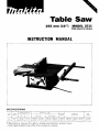
1
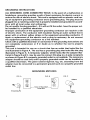
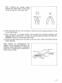
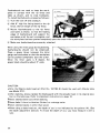
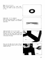
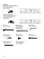
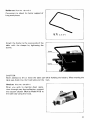
Table Saw
255 mm (10") MODEL 2711
With Electric Brake
INSTRUCTION MANUAL
SPEC IFI CAT I 0NS
Arbor
thole
Blade
dldnlPtel
255 m n ,
iio"i
Table size IL x WI
Cutt,ng C a P d C m e F
90"
91 m m
13 9 16'1
45"
63 nirn
'I
12 1
z
Fixed table
600 m m x 405 inmi
x 15 15 16 I
1 2 3 5 8'
No load
295 mm x 497 mm
111 5 8 ' x 19 $ ) I 6 I
Dimensions
IL
Sliding table
3 800
R k "
1 0 9 0 m m x 715 m m x 4 7 0 mm
142 7 < a x 2 8 im"
i a i:z' I
Manufacturer reserves the right to change specifications without notice.
* Note. Specifications may differ from country to country.
x W x HI
Ne,
wetghf
32 5 kg
1716 ibsi
For Your Own Safety Read Instruction
Manual Before Operating Table Saw
GENERAL SAFETY PRECAUTIONS
(For All Tools)
1 KNOW YOUR POWER TOOL. Read the owner's manual carefully. Learn the
tools applications and limitations, as well as the specific potential hazards
peculiar t o it.
2. KEEP GUARDS IN PLACE and in working order.
3. REMOVE ADJUSTING KEYS AND WRENCHES. Form habit of checking t o
see that keys and adjusting wrenches are removed from tool before turning
it on.
4. KEEP WORK AREA CLEAN. Cluttered areas and benches invite accidents.
5. DON'T USE IN DANGEROUS ENVIRONMENT. Don't use power tools in damp
or wet locations, or expose t h e m t o rain. Keep work area well lighted.
6 . KEEP CHILDREN AWAY. All visitors should be kept safe distance from work
area.
7. MAKE WORKSHOP KID PROOF w i t h padlocks, master switches, or by
removing starter keys.
8. DON'T FORCE TOOL. It will do the job better and safer at the rate for which
it was designed.
9. USE RIGHT TOOL. Don't force tool or attachment t o do a job for which it
was not designed.
10. WEAR PROPER APPAREL. Wear no loose clothing, gloves, neckties, rings.
bracelets, or other jewelry which may get caught i n moving parts. Nonslip
footwear is recommended. Wear protective hair covering t o contain long hair.
11. ALWAYS USE SAFETY GLASSES. Also use face or dust mask if cutting operation is dusty. Everyday eyeglasses only have impact resistant lenses, they
are NOT safety glasses.
12. SECURE WORK. Use clamps or a vise t o hold work when practical. It's safer
than using your hand and it frees both hands t o operate tool.
13. DON'T OVERREACH. Keep proper footing and balance at all times.
14. MAINTAIN TOOLS WITH CARE. Keep tools sharp and clean for best and
safest performance. Follow instructions for lubricating and changing accessories.
15. DISCONNECT TOOLS before servicing; when changing accessories such as
blades, bits, cutters, and the like.
16. REDUCE THE RISK OF UNINTENTIONAL STARTING. Make sure switch is
i n off position before plugging in.
2
17. USE RECOMMENDED ACCESSORIES. Consult the owner’s manual for
recommended accessories. The use of improper accessories may cause risk
of injury t o persons.
18. NEVER STAND ON TOOL. Serious injury could occur if the tool is tipped or
if the cutting tool is accidentally contacted.
19. CHECK DAMAGED PARTS. Before further use of the tool, a guard or other
part that is damaged should be carefully checked t o determine that it will
operate properly and perform its intended function - check for alignment
of moving parts, binding of moving parts, breakage of parts, mounting, and
any other conditions that may affect its operation. A guard or other part that
is damaged should be properly repaired or replaced.
20. DIRECTION OF FEED. Feed work into a blade or cutter against the direction
of rotation of the blade or cutter only.
21. NEVER LEAVE TOOL RUNNING UNATTENDED. TURN POWER OFF. Don’t
leave tool until it comes t o a complete stop.
22. PROPER GROUNDING. This tool should be grounded while in use t o protect
the operator from electric shock.
23. EXTENSION CORDS: Use only three-wire extension cords which have threeprong grounding-type plugs and three-pole receptacles which accept the
tool’s plug. Replace or repair damaged or worn cord immediately.
VOLTAGE WARNING: Before connecting the tool t o a power source (receptacle,
outlet, etc.) be sure the voltage supplied is the same as that specified on the
nameplate of the tool. A power source w i t h voltage greater than that specified
for the tool can result in SERIOUS INJURY t o the user - as well as damage t o
the tool. If in doubt, DO NOT PLUG IN THE TOOL. Using a power source w i t h
voltage less than the nameplate rating is harmful t o the motor.
3
GR 0U N D IN G INSTRUCTIONS
ALL GROUNDED, CORD-CONNECTED TOOLS: In the event of a malfunction or
breakdown, grounding provides a path of least resistance for electric current t o
reduce the risk of electric shock. This tool is equipped w i t h an electric cord having an equipment-grounding conductor and a grounding plug. The plug must be
plugged into a matching outlet that is properly installed and grounded in accordance w i t h all local codes and ordinances.
Do not modify the plug provided-if it will not fit the outlet, have the proper outlet installed by a qualified electrician.
Improper connection of the equipment-grounding conductor can result in a risk
of electric shock. The conductor w i t h insulation having an outer surface that is
green w i t h or without yellow stripes is the equipment-grounding conductor. If
repair or replacement of the electric cord or plug is necessary, do not connect
the equipment-grounding conductor t o a live terminal.
Check w i t h a qualified electrician or serviceman if the grounding instructions are
not completely understood, or if in doubt as t o whether the tool is properly
grounded.
This tool is intended for use on a circuit that has an outlet that looks like the
one illustrated in Figure A. The tool has a grounding plug that looks like the plug
illustrated in Figure A. A temporary adapter, which looks like the adapter illustrated in Figure B and C, may be used t o connect this plug t o a 2-pole receptacle
as shown in Figure B if a properly grounded outlet is not available. The temporary
adapter should be used only until a properly grounded outlet can be installed by
a qualified electrician. The green-colored rigid ear, lug, etc. extending from the
adapter must be connected t o a permanent ground such as a properly grounded
outlet box.
GROUNDING METHODS
FIG. A
FIG. B
FIG. C
Adaoter
QI
Grounding Pin
4
Cover of Grounded
Outlet Box
-
9'
Grounding
Means
ADDITIONAL SAFETY RULES
1. Wear eye protection.
2. Don't use the tool in presence of flammable liquids or gases.
3. Never use the tool w i t h an abrasive cut-off wheel installed.
4. Check the blade carefully for cracks or damage before operation. Replace
cracked or damaged blade immediately.
5. Clean the spindle, flanges (especially the installing surface) and hex nut
before installing the blade. Poor installation may cause vibration/wobbling
or slippage of the blade.
6.Use saw-blade guard and spreader for every operation for which it can be
used, including all through sawing operations. Through sawing operations
are those in which the blade cuts completely through the workpiece as in
ripping or cross cutting. Never use the tool w i t h a faulty blade guard or
secure the blade guard w i t h a rope, string, etc. Any irregular operation of
the blade guard should be corrected immediately.
7. Avoid cutting nails, screws, etc. Inspect for and remove all nails, screws and
other foreign matter from the workpiece before operation.
8. Remove wrenches, cut-off pieces, etc. from the table before the switch is
turned on.
9. Never wear gloves during operation.
IO. Keep hands out of the line of saw blade. Do not stand or permit anyone else
t o stand in line w i t h the path of the saw blade.
11. Make sure the blade is n o t contacting the spreader or workpiece before the
switch is turned on.
12. Before cutting an actual workpiece, let the tool run for a while. Watch for
vibration or wobbling that could indicate poor installation or a poorly balanced
blade.
13. Use a push stick when required. Push sticks should be used for ripping
narrow workpieces t o keep your hands and fingers well away from the blade.
14. Pay particular attention t o instructions for reducing risk of KICKBACK.
KICKBACK is the ejection of the workpiece from the tool back towards the
operator. Avoid KICKBACKS by keeping the blade sharp, by keeping the rip
fence parallel t o the blade, by keeping the spreader, antikickback fingers and
blade guard in place and operating properly, by not releasing the workpiece
until you have pushed it all the way past the blade, and by not ripping a workpiece that is twisted or warped or does not have a straight edge t o guide
along the fence.
15. Do not perform any operation freehand. Freehand means using your hands
t o support or guide the workpiece.
16.Never reach around or over saw blade.
17. Avoid abrupt, fast feeding. Feed as slowly as possible when cutting hard
workpieces. Do not bend or t w i s t workpiece while feeding. If you stall or
5
jam the blade in the workpiece, turn the tool off immediately. Unplug the
tool. Then clear the jam.
18. Never remove cut-off pieces near the blade or touch the blade guard while
the blade is running.
19. Don't abuse cord. Never yank cord t o disconnect from receptacle. Keep cord
away from heat, oil, water and sharp edges.
SAVE THESE INSTRUCTIONS.
6
Movement and transport of table saw
Before moving the table saw, tighten the
wing bolt to secure the sliding table.
When moving the table saw, hold it by the
fixed table and the bars.
Be sure to use two persons to lift and move
it. When transporting the table saw by
vehicle, secure it with a rope or other substantial means.
ASSEMBLY
The table saw is shipped from the factory with the ruler guides, miter gauge, saw blade,
rip fence, blade guard and table insert not installed. Assemble as follows.
CAUTION :
Always be sure that the tool is switched off and unplugged before assembly.
Installing ruler guides
Sliding fable
Fixed fable
Install the graduated ruler guide on the
front side of the fixed table and the nongraduated one on the rear side. Use the hex
wrench to tighten the bolts.
7
Installing miter gauge
Insert the wooden gauge into the miter
gauge and tighten the two screws lightly
but firmly. The wooden gauge will be used
later to help you accurately make crosscuts.
Place the miter gauge on the sliding table
with the wooden gauge extending toward
the fixed table. Insert the longer miter
gauge installation screw through the hole
(A) in the miter gauge and screw it into the
threaded hole in the sliding table. Insert
the shorter miter gauge installation screw
through the hole (B) and screw it into the
nut in the sliding table. Loosen the wing
bolt securing the sliding table before moving the sliding table.
Installing or removing saw blade
Hold the outer flange with the offset
wrench and loosen the hex nut clockwise
with the wrench (the hex nut has left hand
thread). Then remove the outer flange and
flange.
8
Install the blade between the two flanges.
Then install the outer flange and hex nut
onto the arbor, making sure the teeth of
the blade are pointing down a t the front
of the table.
To secure the blade in place, hold the outer
flange with the offset wrench, then tighten
the hex nut counterclockwise with the
wrench. When tightening the hex nut, the
offset wrench handle should be supported
by the table as shown in the figure. BE
SURE TO TIGHTEN THE HEX NUT
SECURELY.
CAUTION :
Be sure to hold the hex nut carefully with the wrench. If your grip should slip, the
wrench may come off the hex nut, and your hand could strike the sharp blade edges.
9
Installing and adjusting rip fence
Loosen the lever on the rip fence and f i t
the rip fence on the ruler guides.
Lever
Rip fence
Ruler guide
To check to be sure that the rip fence is
parallel with the blade, secure the rip fence
2 - 3 mm (5/64"- 1/8") from the blade.
Raise the blade up to maximum elevation.
Mark one of the blade teeth with a crayon.
Measure the distance (A) and (B) between
the rip fence and blade. Take both measurements using the tooth marked with the
crayon. These two measurements should
be identical. I f the rip fence i s not parallel
with the blade, proceed as follows:
Insert a screwdriver into the hole in the
rear end of the rip fence, then loosen
the screw counterclockwisetwo or three
turns.
Loosen the two bolts on the top of the
rip fence with the wrench.
Adjust the rip fence until it becomes
parallel with the blade, then secure it by
tightening the bolts.
Tighten the screw in the hole in the rear
end of the rip fence clockwise two or
three turns.
10
1 I
Tighen the lever on the rip fence. I f the rip
fence is not secure enough, leave the lever
in the tightened position and tighen the
screw in the hole in the rear end of the rip
fence clockwise. However, do not tighten
the screw excessively, or the lever will become loose.
I
CAUTION :
Be sure to adjust the rip fence parallel with the blade, or a dangerous kickback condition
may occur.
Move the rip fence a bit away from the
blade and secure it. Use a ruler to measure
the distance (A) between the rip fence and
blade. Make sure that the pointer on the
ruler guide points to the correct graduation.
I f the pointer does not point to the correct
graduation, loosen the screw on the pointer.
Then align the pointer with the correct
graduation and tighten the screw.
Blade
11
Installing blade guard
CAUTION :
Before installing the blade guard, adjust the depth of cut to i t s maximum elevation.
(Note: The depth of cut is adjusted to i t s maximum elevation when the table saw i s
shipped from the factory.)
Temporarily tighten the bolts with the
offset wrench. Check to be sure that the
blade and spreader are in a straight line.
I f they are not properly aligned, shift the
adjusting washers from one side to another
until the spreader is aligned directly behind
the blade.
These two clearances
should be equal.
h
r--l
washer
K'
Spreader
/
Pressure plate
Blade
Bolt
CAUTION :
I f the blade and spreader are not aligned properly, a dangerous pinching condition may
result during operation. Make sure they are properly aligned.
There must be a clearance of about 4 5 mm (5/32"-13/64") between the spreader
and the blade teeth. Adjust the spreader
accordingly and tighten the bolts securely.
Attach the table insert on the table, then
check to see that the blade guard works
smooth.
1I
Soreader
- , ----
CAUTION :
Be sure to tighten the screws securely after installing the table insert.
12
1I
Positioning table saw
Locate the table saw in a well lit and level
area where you can maintain good footing
and balance. It should be installed in an
area that leaves enough room to easily
handle the size of your workpieces. The
table saw should be secured with four
screws or bolts to the work bench or table
saw stand (optional accessory) using the
holes provided in the bottom of the table
saw. When securing the table saw on the
work bench, make sure that there is an
opening in the top of the work bench the
same size as the opening in the bottom of
the table saw so the sawdust can drop
through.
No. 10 wood screw
40 mm I l - l / Z ’ ’ l min. length
If during operation there is any tendency for the table saw to tip over, slide or move, the
work bench or table saw stand should be secured to the floor.
13
Hand tool storage pocket
The table saw comes with a hand tool
storage pocket in the base. Keep wrenches,
screwdriver, etc. in this pocket.
I
Adjusting depth of cut
The depth of cut may be adjusted by turning the knob. Turn the knob clockwise
to raise the blade or counterclockwise to
lower it. The depth of cut i s indicated on
the scale by the pointer (A).
If the knob does not turn easily, loosen the
two adjusting screws on the inside of the
table saw counterclockwise. If the knob is
loose enough to be turned by vibration,
tighten the adjusting screws clockwise.
14
1
Bevel cutting
Loosen the lock lever clockwise, then tilt
the blade by swinging the knob until it
reaches the desired angle ( 0 to 45 degrees).
The bevel is indicated on the scale by
the pointer (B). After obtaining the desired
angle, tighten the lock lever counterclockwise to secure the adjustment.
CAUTION :
After adjusting the bevel, be sure to tighten the lock lever securely.
Adjusting stopper plate
Secure the lock lever a t the position where
the lock lever contacts the stopper plate.
Make sure the blade is a t 90 degrees or 45
degrees to the table surface. I f the bevel
is not a t 90 degrees or 45 degrees, proceed
as follows:
:I, Use the hex wrench to loosen the bolt
securing the stopper plate.
Z Loosen the lock lever and adjust the
blade to 90 degrees or 45 degrees, then
secure the lock lever.
3 Slide the stopper
plate until it contacts
the lock lever, then tighten the bolt
securely.
@ Make sure the pointer (B) points to the 0" or 45" graduation on the bevel scale when
the blade i s a t 90 degrees or 45 degrees. I f it does not point to the 0" or 45" graduati!,
o
loosen the screws holding the pointer (B) and align the pointer (B)with the 0" or
45 graduation. Then tighten screws. (Note: The screws holding the pointer (B) are
located inside the base.)
1s
Adjusting miter angle
Loosen the miter gauge installation screws
and adjust the miter gauge to the desired
angle (0 to 45 degrees). Then tighten the
miter gauge installation screws securely.
CAUTION :
After adjusting the miter angle, be sure to tighten the miter gauge installation screws
securely.
Switch action
To start the tool, press the "ON" button
while the key is pressed in. Press the"0FF"
button to stop.
When operating the key and switch buttons,
it is convenient to view them through the
window area in the fixed table.
CAUTION :
When not using the tool, remove the key and store it in a secure place. This prevents
unauthorized operation.
16
Operation
CAUTION :
*Make sure the blade guard works smoothly and properly for making both square cuts
and bevel cuts before operation.
*Never withdraw the workpiece while the blade i s running. I f you must withdraw the
workpiece before completing a cut, first switch the tool off while holding the workpiece firmly. Wait until the blade has come to a complete stop before withdrawing the
workpiece. Failure to do so may cause dangerous kickback.
Never remove cut-off pieces that may be trapped inside the blade guard while the blade
is running.
When moving the sliding table, do not place your fingers or hands on the reverse side of
the sliding table. You may get your fingers pinched between the sliding table and bars.
Work helpers
Push sticks, push blocks or auxiliary fence are types of "work helpers." Use them to
make safe, sure cuts without the need for the operator to contact the blade with any part
of the body.
Push stick
A push stick can be easily made from a piece of plywood 19 mm (3/4")to 25 mm (1")
thick.
130 mm 15")
(HI
mm
9 5 mm 3/8"1
19 mm
(314"I
40 mm
(1-1 12"l
'1
380 mm (15"l
Cut out the hatched area on the stick and smooth edges with a file. (H) dimension should
be less than 12.7 mm (1/2") so as to be thinner than the workpiece.
17
Push block
Use a 19 mm (3/4") piece of plywood.
120
.
mm
Faceledge
parallel
(5")
(5")
6 mm
(1/4"l 5o mm
(2")
Handle should be in center of plywood piece. Fasten with glue and wood screws as shown.
Small piece 9.5 mm x 8 mm x 50 mm (3/8"x 5/16" x 2") of wood must always be glued
to plywood to keep the blade from dulling if the operator cuts into push block by mistake. (Never use nails in push block.)
Auxiliary fence
Make auxiliary fence from 9.5 mm (3/8")
and 19 mm (3/4")plywood pieces.
1 9 mm (314'')
9.5 mm
Faceledge
parallel
(18")
4 0 mm
(1 -1 12" I
(5-112")
Fasten with glue and wood screws.
Wood facing (Rip fence)
A wood facing should be used for operations when the blade comes close to the
rip fence. Wood facing for the rip fence
should be same size as the rip fence.
Make sure the bottom of facing is flush
with the table surface.
18
Crosscutting
CAUTION :
When making a crosscut, remove the rip fence from the table.
When cutting long or large workpieces, always provide adequate support to the sides of
the table. The support should be a t the same height as the table.
(1; Loosen the wing bolt securing the sliding table.
0)Adjust
the blade to 90 degrees to the
table surface. Adjust the miter gauge to
0 degree. Switch the tool on and move
the sliding table forward to cut the
wooden gauge.
Align the cutting line on the workpiece
with the end of the wooden gauge.
131 Adjust the depth
of cut a bit higher
than the thickness of the workpiece.
Firmly hold the workpiece flush against
the miter gauge and move the sliding
table forward gently to cut the workpiece.
Miter cutting
Adjust the miter gauge to the desired angle
( 0 to 45 degrees) and tighten the miter
gauge installation screws securely. Follow
the same procedure as’mentioned in @ for
crosscutting.
19
The wooden gauge cannot be used for miter cutting.
NOTE:
Miter cutting capacity is less than crosscutting capacity. Make sure of the max miter cutting capacity before operation.
The following reference table indicates some examples of miter cutting capacity.
Cutting capacity
Miter angle
Bevel angle
0"
I
Thickness
I
Width
290 mm
(1 1 -3/8")
n
4
l
O0
19 mm
(3/4")
45
* 63"
260 mm
(1 0-1 /4")
(2-1/2")
210 mm
(8-1 /4")
19 mm
(3/4")
255 mm
(10")
55mm
(2-1/8")
220 m m
(8-5/8")
0"
*
45O
* 18mm
(23/32")
270 mm
( 1 0-5/8")
45"
0"
45"
* 91"
(3-9/1 6" )
70 mm
(2-3/4")
19 mm
(3/4")
60 mm
(2-3/8")
max. thickness at each angles.
(The illustrations in the reference table show the table saw in use with the blade guard
removed. This is done only in the interest of the clarity of the illustrations and should
not be construed as a normal working procedure.)
20
When a spacer block can be placed between
the miter gauge and workpiece, you can
obtain a greater miter cutting capacity.
Ripping
CAUTION
When ripping, remove the miter gauge from the sliding table.
.When cutting long or large workpieces, always provide adequate support behind the
table. The support should be a t the same height as the table.
Before operating the table saw, check to be sure that the antikickback fingers operate
properly. Turn the tool off and unplug it. Feed the workpiece under the blade guard and
along both sides of the blade to simulate cutting. Try to withdraw the workpiece on each
side by pulling it toward you. The antikickback fingers should grab the workpiece and
prevent it from moving back toward the operator. Always keep the antikickback fingers
sharp so they will operate properly. Keep them sharp by using round -shaped file to
maintain the original shape of the fingers.
@ Adjust the depth of cut a bit higher than the thickness of the workpiece.
@ Tighten the wing bolt to secure the sliding table.
@)
Position the rip fence to the desired
width of rip and lock in place by tightening the lever. Before ripping, make sure
the rear end of the rip fence is secured
firmly. I f it i s not secured enough,
follow the procedure in "Adjusting rip
fence". (P.11)
a Turn the tool
on and gently feed the
workpiece into the blade along with the
rip fence.
21
i) When the width of rip i s 150 mm (6")
and wider, carefully use your right
hand to feed the workpiece. Use your
left hand to hold the workpiece in
position against the rip fence.
ii) When the width of rip i s 65 mm 150 mm (2-1/2" - 6") wide, use the
push stick to feed the workpiece.
iii) When the width of rip is narrower than
65 mm (2-1/2"), the push stick cannot
be used because the push stick will
strike the balde guard. Use the auxiliary fence and push block. Attach the
auxiliary fence to the rip fence with
two "C" clamps.
22
I
Feed the workpiece by hand until the
end is about 25 mm ( I ” ) from the
front edge of the table.
Continue to feed using the push block
on the top of the auxiliary fence until
the cut is complete.
23
MA1NT ENANCE
CAUTION :
Always be sure that the tool is switched off and unplugged before attempting to perform
inspection or maintenance.
Cleaning
Clean out sawdust and chips from time to time.
Carefully clean the balde guard and moving parts inside the table saw.
Lubrication
To keep the table saw in tip-top running condition, and to assure maximum service life,
oil or grease the moving parts and rotating parts from time to time.
Use machine oil #I20 to wet the felt on
the slide table and the bars.
Use grease or machine oil #I20 for the
moving parts under the table.
Replacing carbon brushes
Remove and check the carbon brushes
regularly. Replace when they wear down to
the timit mark. Keep the carbon brushes
clean and free to slip in the holders. Both
carbon brushes should be replaced a t the
same time. Use only identical carbon
brushes.
Use a screwdriver to remove the brush
holder caps. To replace the carbon brush
in the side near the table, lower the blade
as far as possible by turning the knob.
Loosen the lock lever, tilt the blade and
secure it a t 45 degrees. Then loosen the
brush holder cap while viewing it through
the opening in the base.
Remove the worn carbon brushes, insert
the new ones and secure the brush holder
caps.
To maintain product SAFETY and RELIABILITY, repairs, any other maintenance or
adjustment should be performed by Makita Authorized or Factory Service Centers,
always using Makita replacement parts.
24
ACCESSORIES
CAUTION :
These accessories or attachments are recommended for use with your Makita tool specified in this manual. The use of any other accessories or attachments might present a risk
of injury to persons. The accessories or attachments should be used only in the proper
and intended manner
Dado head set (Part No 191794-9)
A dado is cutting a rabbet or a wide groove
into the workpiece. The dado head set consists of two outside cutters, five inside
cutters and three rings.
Outside cutters
Inside cutters
Inside cutter
Rings
Paper washers
: 6" diameter, 1/8" thick, 5/8" arbor hole, 2 pcs.
: 6" diameter, 1/8" thick, 5/8"
: 6" diameter, 1/16" thick, 5/8"
518"
:
5/8"
arbor hole, 4 pcs.
arbor hole, 1 pc.
arbor hole, 3 pcs.
arbor hole, 6 pcs.
Various combinations of these cutters are used to cut grooves from 1/8" to 13/16" for
use in making joints, tenoning, grooving, etc.
To install the dado head set, proceed as follows:
Turn the tool off and unplug it before installing.
1(:
(2;
Remove the blade guard with the spreader.
3, Install the dado head s e t with the teeth pointing down a t the front of the table
25
@ Use the chart below to select the proper cutters to obtain the various cutting widths.
Flange
Outslde
cutter
Ring
,',~~~e
cutter
I
-*+tI
I
114"
I
I
5116"
I
I
I
1 0 x 2
7/16"
112"
0
9/16"
I
I
o x 3
518"
I
o
11116"
0
314"
13116"
0
0
1 0 x 4
0
0
0
CAUTION :
For a 1/8" cut width, the outside cutter is assembled to the spindle in the same manner
as the saw blade.
The outer flange must be used for each cut width.
The hex nut alone must not be used to secure the dado on to the spindle.
NOTE :
When widths slightly greater than the above are required, fit the paper washers in between
the inside and outside cutters to adjust the width.
@ Arrange the cutters so that the tips of
the inside cutters are positioned a t the
gullets of the outside cutter.
When more than one inside cutter i s
used, space the tips of the inside cutters
equidistantly in relation to one another.
Poorly spaced cutters may cause vibration and noise.
26
When installing two outside cutters
without any inside cutter, be sure that
the cutter tips do not face each other.
0
X
@ While tightening the hex nut, be careful to maintain the even spacing between the tips
of the inside cutters.
@ When cutting 1/2" or narrower grooves, use the table insert originally installed on the
table saw. When cutting 9/16" or wider, use optional accessory table insert (Part No.
343396-9). Be sure to install proper table insert.
@ Rotate the dado head one turn by hand to make sure that it does not contact anything
before operation.
When dadoing, use featherboards. The
diagram shown illustrates dimensions for
making a typical featherbord. It should be
made from a straight piece of wood that i s
free of knots or craks.
Kerf should be
27
Featherbords are used to keep the workpiece in contact with the rip fence and
table as shown, and to stop kickbacks.
To install featherbords. proceed as follows :
@ Turn the tool off and unplug it.
@ Add 8" high flat facing board to the rip
fence, the full length of the rip fence.
@ Mount featherboards to the rip fence
and table as shown, so that the leading
edges of featherboard will support the
workpiece until the cut is complete, and
the workpiece has been pushed completely past the cutter with a push stick.
@ Make sure featherboards are securely attached.
When using the miter gauge during dodoing,
featherboards should not be employed.
Place a spacer block between the miter
gauge and workpiece so that the workpiece
can be pushed completely past the cutter.
When the miter agnle is 0 degree, the
spacer block should be about 3" wide.
CAUTION :
*Only the Makita dodo head set (Part No. 191794-9) should be used with Makita table
saw Model 271 1.
*After dadoing, always replace the blade guard with the spreader back in i t s original position on the table saw. Refer to alignment instructions on page 12.
Never attempt bevel cuts when dadoing.
Never dado if there is vibration (flutter) or a strange noise.
Never attempt dados in other than wood.
*When using a dado head set, the depth of cut is not indicated by the pointer (A). (See
the depth adjustment section.) To know the depth of cut, you must measure it with a
ruler.
28
Ring (Part No. 257137-6)
When cutting groove 1/4", 5/16", 3/8",
7/16", 1/2", 9/16" or 5/8", use this ring
or rings.
Table insert (Part No. 343396-9)
When cutting grooves 9/16" or wider, use
this table insert instead of the standard
table insert.
Table saw stand (Part No. STEX 122251 1
Place the stays on a level location and
assemble the legs inside. Secure with the
bolts and nuts, then attach the rubber caps
to the ends of the legs.
Now set the table saw on top of the assembled stand and secure with four bolts,
washers and nuts.
29
Saw blades
0
Chisel tooth combination saw blade
For rip and cross-cut work.
Most frequently used for
general carpentry.
Hole
Part No.
255-7A
0
I
255 (10")
I
518''
I
36
1 792317-2
Carbide-tipped saw blade
Fastest, smoothest longer sawing
without blade sharpening cuts
wood, drywall, plastic,
hardwood, etc.
Hole
Part No.
I
255-11F
0
Ruller guide F
Part No. 331308-4
Rip fence
Part No 122328-7
0
!Screwdriver 2
Part No. 783002-8
0
Offset wrench 1 3 - 2 2
Part No. 782015-6
30
I
0
Ruller guide R
Part No. 331293-1
0
Switch button
Part No. 41 1447-7
Hex socket head bolt
(For ruller guide)
Part No. 922337-4
I
I
255 (10")
I
I
5/8"
I
22
0
Hex wrench 5
Part No. 783203-8
0
Wrench 1 9
Part No. 781010-3
1792424-1
Holder set (Part No. 191773-7)
Convenient to attach for better support of
long workpieces.
Attach the holder to the reverse side of the
I
I
CAUTION :
Never attempt to lift or move the table saw while holding the holders. When moving the
table saw, hold it by the fixed table and the bars.
Hood set (Part No. 191793-1)
When you wish to maintan clean operations through easy dust collection, connect
the vacuum cleaner (Makita Model 410) t o
the table saw using this hood.
31
Jan
255 mm (IO")
TABLE SAW
Model 2711
32
2 2 ' 8 7 US
Note. The switch and other part configurations
may differ from country to country
33
Jan
MODEL 2711
$FD
sD
DESCRIPTION
DESCRIPTION
MACHINE
~
2
3
4
5
6
7
8
9
IO
11
12
13
14
15
16
17
18
19
20
21
22
23
24
26
27
28
29
30
31
32
33
34
35
36
37
38
39
40
41
42
43
44
45
46
47
48
49
50
51
52
53
54
55
56
57
58
59
60
61
62
63
64
~
2
1
2
2
4
1
1
1
1
1
1
1
2
1
1
1
1
1
1
1
1
1
1
1
1
7
1
2
1
4
4
1
1
1
2
1
1
1
1
1
1
1
1
1
1
1
1
1
1
2
1
1
2
1
1
1
1
1
1
1
1
2
1
-
Hex Bolt M 5 r 6 5 [With Washer]
Rubber Pin 4
Brush Holder Cap
Carbon Brush
Pan Head Screw M5x40 [With Washerl
PO"
Motor Housing
Flat Washer 18
Ball Bearing 620oC8
Dust Seal 10
FIELD ASSEMBLY
Baffle Plate
Pan Head Screw M4x10 [With Warherl
Terminal Box
ARMATURE ASSEMBLY
IWiih Item 9 1 0 & 15
181
Fan 97
Dust Seal 1 5
Ball Bearing 6202LLB
Rubber Pin 6
Pan Head Screw M4x8 [With Washerl
Gear Housing
Cord
Pan Head Screw M4x14 IWlth Washer)
Strain Relief
Blade Guard
Adjusting Washer
Pressure Plate
Hex Bolt M a r 2 5 [With Washeri
Woodruff Key 4
Pan Head Screw M 5 r 3 0 lWilh Washeri
Hex Bolt M 6 r 1 6 lWith Warherl
Retaining Ring S - 17
Needle Bearing 121 5
Tension Spring 14
Pan Head Screw M5x30 [With Washer)
Retainer
Compresston Spring 24
Reta,"e.
Nylon Pin 10
Feed Nu1
Hex Bolt M 1 0
Flat Washer 12
Link
Flat Washer 10
Hex Bolt M 1 0 x I B
Set Screw M5x6
Lock Lever
Knob 45
Spring Pin 5 16
Pan Head Screw M4x10 [With Washer)
Screw Guide
Screw Bar M 1 2
Pan Head Screw M5x8 IWgth Washer1
PO,"fe,
Flat Washer 9
Spring Washer I O
Hex Nut M 1 0
Flat Washer 9
Sleeve 9
Spring Pm 5 - 16
Chip Guide
Pan Head Screw M5x8 IWGth Washerl
Frame
65
66
67
68
69
70
71
72
74
75
76
77
78
79
80
81
82
83
84
85
86
87
88
89
90
91
92
93
94
95
96
97
98
99
100
101
102
103
104
105
106
107
108
109
I10
111
112
113
114
115
116
117
I18
119
120
121
122
123
124
125
126
127
901
1
1
1
1
1
1
1
1
1
1
1
1
1
1
1
3
2
1
1
2
1
4
4
4
4
4
2
1
2
2
1
2
4
4
2
1
1
2
2
1
1
2
2
1
2
2
1
1
1
2
4
1
4
5
2
1
2
1
2
2
2
1
2
- __
Note The SWttch and other pail specificatmns may difler trom country to country
34
Inner Race 8 1 0
=,n 8
ielical Gear 49
W a i n i n g Ring S
nouslng
20
COW
3811 Bearing 6204LLB
3earing Retainer 31 48
Spindle
Duter Flange 30
Hex Nu1 M 1 2 19
Screw M I 0
Screw M 1 0
'Aler Gauge Guide
Utter Gauge Plate
l e x Nut M 1 0
Countersunk Head Screw M5116
Pan Head Screw M5x12
Wooden Gauge
Table Insert
P a n Head Screw M6x16
Flxed Table
Hex Socket Head Bolt M6x16
Flaf Washer 8
Hex Socket Head Bolt M a x 4 0
Hex Socket Head Boll M6x35
Flat Washer 6
Holder Bar
Sliding Table
Felf
Slide Guide R
Slide Bar
Set Plate
Pan Head Screw M5x25 lWilh Washerl
Felt
Slide Guide L
Slide Bar
Slide Stopper
Pan Head Screw M6x16 lWith Washerl
Cushion
Compression Spring I
Wing Bolt M5x25
Set Plate
Pan Head Screw M5x16 IWith Washer]
Switch
Cord Guard
Pan Head Screw M4x25 lWith Washer]
Strain Relief
Cord Guard
Cord
Pan Head Screw M3x35
Cap 20
Base
Hex Nut M 6
Pan Head S c r e w M6x25 IWith Washer1
Stopper Plate
Front Plate
Pan Head Screw M6x16 lWith Washer]
Name Plate
Pan Head Screw M6x22 lWith Wdsherl
Flat Washer 6
Hex Socket Head Boll M 6 x l O
Lock Off Switch Button
Flange 50
22
8 7 US
MAKITA LIMITED ONE YEAR WARRANTY
Warranty Policy
Every Makita tool is thoroughly inspected and tested before leaving the factory. It is warranted t o
be free of defects from workmanship and materials for the period of ONE YEAR from the date of
original purchase. Should any trouble develop during this one-year period, return the COMPLETE
tool, freight prepaid, t o one of Makita’s Factory or Authorized Service Centers. If inspection shows
the trouble is caused by defective workmanship or material, Makita will repair (or at our option,
replace) without charge.
This Warranty does not apply where:
8 repairs have been made or attempted by others:
8 repairs are required because of normal wear and tear
8 The tool has been abused, misused or improperly maintained;
8 alterations have been made t o the tool.
IN NO EVENT SHALL MAKITA BE LIABLE FOR ANY INDIRECT, INCIDENTAL OR CONSEQUENTIAL DAMAGES FROM THE SALE OR USE O F THE PRODUCT. THIS DISCLAIMER
APPLIES BOTH DURING AND AFTER THE TERM OF THIS WARRANTY.
MAKITA DISCLAIMS LIABILITY FOR ANY IMPLIED WARRANTIES, INCLUDING IMPLIED
WARRANTIES O F “MERCHANTABILITY” AND “FITNESS FOR A SPECIFIC PURPOSE,”
AFTER THE ONE-YEAR TERM O F THIS WARRANTY.
Tlu, Warranty g~vesyou spe~ificlegal nghts. dnd you may also have other nghts WhiLh vdry from
\talc 10 state. Some states d o not allow the exclusion or limitdtion 01 incidental or consequentidl
damages, so the above limitation or exclusion may not apply to you. Some states do not allow
limitation on how long an implied warranty lasts, so the above limitation may not apply to you.
Makita Corporation
3-11-8, Sumiyoshi-cho,
Anjo, Aichi 446 Japan
88357 1BOW
PRINTED IN JAPAN
1993-4-N